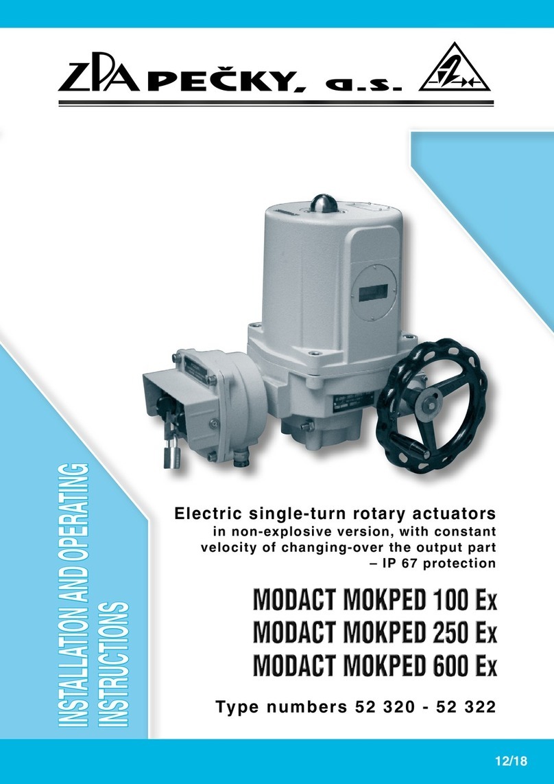
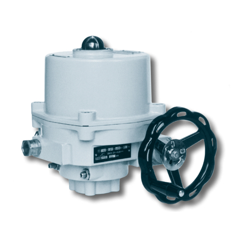
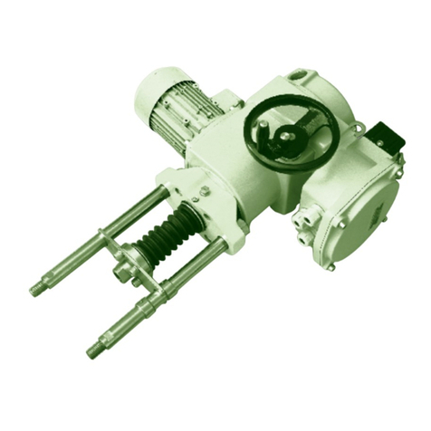
ZPA Pecky, a.s. MODACT MTN User manual

Type numbers 52 442, 52 443
Electric Linear (Pull-rod)
actuators
4/19
MOUNTING INSTRUCTIONS

ZPA Pečky, a.s. is certified company in accordance with ISO 9001 as amended.

3
1. APPLICATION
The MODACT MTN, MTP actuators are used for remote two-position or three-position control of the valves by
a reverse rectilinear motion.
The MODACT MTN, MTP Control actuators are fitted with an electronic position controller. In association with
the valve exhibiting a suitable control characteristic, they form a position servo-loop. The output pull-rod of these
actuators is automatically brought into a position corresponding to the input signal value of the controller.
The actuators can be used even for other devices for which they are in respect of their characteristics and parameters
suitable. In some special cases, the contemplated use of the actuators should be consulted with the manufacturer.
2. OPERATING CONDITIONS, OPERATING POSITION
Operating conditions
The MODACT MTN, MTP (MODACT MTN, MTP Control) actuators should withstand the effect of operating
conditions and external influences, Classes AC1, AD5, AD7, AE4, AE6, AF2, AG2, AH2, AK2, AL2, AM-2-2, AN2,
AP3, BA4 and BC3 according to ČSN 33 2000-5-51 ed. 3.
When placed on an open area, the actuator is recommended to be fitted with a light shelter to protect it
against direct action of atmospheric effects. The shelter should overhang the actuator contour by at least 10 cm
at the height of 20 – 30 cm.
If the actuator is used at a location with an ambient temperature under +10 °C and/or relative humidity above
80 %, at a sheltered location, or in the tropical atmosphere, the anti-condensation heater which has been built in all
actuators, should be always used. One or two heater elements should be connected, as required.
Installation of the actuators at a location with incombustible and non-conducting dust is possible only if this has no adverse
effect on their function. It is advisable to remove dust whenever the layer of dust becomes as thick as about 1 mm.
Notes:
A sheltered location is considered a space where atmospheric precipitations are prevented from falling at an angle
of up to 60° from the vertical.
The location of the electric motor should be such that cooling air has free access to the motor and no heated-up
blown-out air is drawn in the motor again. For air inlet, the minimum distance from the wall is 40 mm. Therefore,
the space in which the motor is located should be sufficiently large, clean and ventilated.
Surrounding temperature
Operating temperature for MODACT MTN actuators is from -25 °C to +70 °C or from -40 °C to +60 °C, for MODACT
MTP actuators from -25 °C to +60 °C.
CONTENS
1. Application ....................................................................................................................3
2. Operating conditions, Operating position .............................................................................. 3
3. Operating mode, Service life of actuators .............................................................................. 4
4. Technical data .................................................................................................................5
5. Actuator outfit ................................................................................................................ 6
6. Electric parameters .......................................................................................................... 8
7. Description ..................................................................................................................... 9
8. Packing and storing ....................................................................................................... 18
9. Checking of the instrument function and its location .............................................................. 19
10. Attachment to a valve ..................................................................................................... 19
11. Adjustment of the actuator with a valve ............................................................................... 19
12. Operation and maintenance ............................................................................................. 19
13. Failures and their removal ............................................................................................... 20
Tables – basic parameters .................................................................................................21–22
Dimensional sketch MTN, MTP ............................................................................................23–26
Wiring diagrams of actuators MTN, MTP ............................................................................... 27–32
Spare parts list ................................................................................................................... 33
4
Classes of external influences – as extracted from ČSN Standard 33 2000-5-51 ed. 3.
Class:
1) AC1 – Altitude ≤ 2,000 m above sea level
2) AD5 – Spouting water; water can spout in any direction
AD7 – Shallow dipping; possibility of occasional partial or complete covering (for the type MTP only)
3) AE4 – Light dustiness
AE6 – Heavy dustiness, (MTP only)
4) AF2 – Corroding atmosphere and pollutants; the presence of corroding pollutants is significant
5) AG2 – Average mechanical stress; in current industrial plants
6) AH2 – Medium vibrations; in current industrial plants
7) AK2 – Serious risk of growth of vegetation and moulds
8) AL2 – Serious danger of the occurance of animals (insects, birds, small animals)
9) AM2-2 – Normal level of signal voltage. No additional requirements.
10) AN2 – Medium solar radiation with intensities > 500 W/m2 and ≤ 700 W/m2
11) AP3 – Medium seismic effects; acceleration > 300 Gal ≤ 600 Gal
12) BA4 – Personal abilities; instructed people
13) BC3 – Frequent contact with the earth potential; persons coming frequently into contat with “live” parts or
standing on a conducting base
Operating position
The actuators MODACT MTN, MTP, type no. 52 442, 52 443 can be used in any operating position.
3. OPERATION MODE,
SERVICE LIFE OF ACTUATORS
Operation mode
According to ČSN EN 60 034-1, actuators can be operated in S2 load category (the course of load is
shown in the picture). The operation time at +50 °C shall be 10 minutes, the average mean load thrust value
shall be below or equal to 60 per cent of the maximum tripping thrust Fv. According to ČSN EN 60 034-1, the
actuators can also be operated in the S4 mode (interrupted operation with acceleration intervals). The load
factor N/N+R shall be maximum 25 per cent, the longest operation cycle N + R is 10 minutes. The maximum
number of switching actions in automatic control mode is 1200 actions per hour. The average mean load thrust
at load factor of 25 per cent and 50 °C shall not exceed 40 per cent of the maximum tripping thrust Fv.
The maximum average mean of the load thrust equals the rated thrust of the actuator.
Corrosion protection
Actuators are standardly delivered with surface treatment corresponding to category of corrosion aggressiveness
C1, C2 and C3 according to ČSN EN ISO 12944-2.
On customer's request is possible to do surface treatment correcponding to category of corrosion aggressiveness
C4, C5-I and C5-M.
In following table is provided and overview of environment for each categories of corrosion aggressiveness accor-
ding to ČSN EN ISO 12944-2.
Corrosion
aggressiveness
level
Example of typical environment
Outdoor Indoor
C1 Heated buildings with clean atmosphere
(very low) e.g. offices, shops, schools, hotels.
C2 Atmosphere with low level of pollution. Unheated buildings, in which may occur
(low) Mostly outdoor areas. condensation, e.g. stocks, sports halls.
C3 Urban industrial atmospheres, Production areas with high humidity and low air
(middle) mild pollution of sulfur dioxide. pollution, e.g. food industry, processing
Seaside areas with middle salinity. factories, breweries.
C4 Industrial areas and seaside areas Chemical plants, swimming pools,
(high) with middle salinity. seaside shipyard.
C5-I
(very high Industrial areas with high humidity Buildings or areas with predominantly continuous
– industrial) and aggressive atmosphere. condensation and high air pollution.
C5-M
(very high Seaside areas with high salinity. Buildings or areas with predominantly
– seaside) continuous condensation and high air pollution.

5
Service life of actuators
The actuator intended for shut-off valves must be able to perform at least 10,000 operating cycles (C - O - C).
The actuator intended for regulating purposes must be able to perform at least 1 million cycles with operation time (during
which the output shaft is moving) at least 250 hours. Service life in operating hours (h) depends on load and number of switching.
Not always, high frequency of switching influences positively accuracy of regulation. For attaining the longest possible faultless
period and service life, frequency of switching is recommended to be set to the lowest number of switching necessary for the
given process. Orientation data of service life derived from the set regulation parameters are shown in the following table.
Service life of actuators for 1 million starts
Service life [h] 830 1 000 2 000 4 000
Number of starts [1/h] Max. number of starts 1200 1 000 500 250
4. TECHNICAL DATA
Supply voltage
The rated supply voltage of the actuators is 3 x 230 / 400 V, 50 Hz with permissible line voltage fluctuations between
+10 % and -15 % and frequency shift within ±2 %.
Protective enclosure
Protection of the actuators MODACT MTN (MODACT MTN Control) – IP 55
MODACT MTP (MODACT MTP Control) – IP 67
Noise
Acoustic pressure level A max. 85 dB (A)
Acoustic power level A max. 95 dB (A)
Tripping thrust
At the factory, the tripping thrust has been adjusted within the min./max. range giving in Table 1, according to the
customer’s requirements. If no tripping thrust adjustment is required the actuator is adjusted to its maximum tripping thrust.
Starting thrust
The starting thrust of the actuator is a calculated value determined by the starting torque of the electric motor and
the total gear ratio and efficiency of the actuator. After run reversation, the actuator can produce a starting thrust for the
duration of 1 to 2 revolutions of the output shaft when torque-limit switching is locked. This can take place in either end
position or in any intermediate position.
Self-locking
The actuator is self-locking provided that the load only acts in the direction against motion of the actuator output shaft.
Self-locking is ensured by a roller arrest immobilizing the electric motor rotor even in the case of manual control.
In order to observe safety regulations, the actuators cannot be used for driving transportation lifting devices with possible
transport of persons or for installations where persons can stand under the lifted load.
Course of working cycle
Fz Starting thrust ≥ 1,3 . Fv
Fstř Average mean load thrust
Fv Maximum mean tripping thrust
Fz
Fstř
Fv
Cycle period
Operating time N Idling time R

6
Working stroke
The ranges of working stroke are given in Table No. 1.
Manual control
Manual control is performed by a hand wheel directly (without a clutch) and it is also possible when the electric motor
is running. By rotating the hand wheel in the clock-wise direction the actuator output pull rod is thrown out (closes).
Torque-limit switches in the actuator are set and work when the actuator is under voltage.
When using the manual control, ie. actuator is controlled mechanically, the torque-limit switches doesn´t
work and the valve can be damaged.
5. ACTUATOR OUTFIT
Torque-limit switches
The actuator is fitted with two torque-limit switches (MO – OPEN, MZ – CLOSE) each of which acts only
in one direction of motion of the actuator output shaft. The torque-limit switches can be set to operate at any
point of the working stroke except the region in which they are locked (see Starting thrust).
The tripping torque can be adjusted within the range shown in Table No. 1. The torque-limit switches are locked
if the load torque is lost after they have been brought into the OFF-position. This feature secures the actuator against
the so-called “pumping”.
Position-limit switches
The PO – OPEN and PZ – CLOSE position-limit switches limit the actuator working stroke, each being adjusted
to operate in either end position.
Position signalling
For signalling position of the actuator output shaft, two signalling switches, i.e. the SO – OPEN signalling switch and
the SZ – CLOSE signalling switch, are used. Each of these switches acts only in one direction of output shaft rotation.
The operating point of the microswitches can be set within the whole working stroke range except the narrow band before
the operating point of the microswitch used to switch off the electric motor.
Position transmitters
The MODACT MTN, MTP electric actuators can be supplied without position transmitter can be fitted with position transmitter:
a) Resistance transmitter 1 x 100
Ω
.
Technical parameters:
Position scanning resistance
Turning angle 0° – 320°
Non-linearity ≤ 1 %
Transition resistance max. 1.4
Ω
Permitted voltage 50 V DC
Maximum current 100 mA
b) Type CPT 1Az passive current transmitter. Power supply to the current loop is not a part of the actuator.
Recommended feeding voltage is 18 – 28 V DC, at maximum loading resistance of the loop 500
Ω
. The current loop
should be earthed in one point. Feeding voltage need not be stabilized; however, it must not exceed 30 V or else
the transmitter could be damaged.
Range of CPT 1Az is set by a potentiometer on the transmitter body and its starting value by corresponding partial
turning of the transmitter.
Technical parameters of CPT 1Az:
Scanning of position capacity
Working stroke adjustable 0° – 40° to 0° – 120°
Non-linearity ≤ 1 %
Non-linearity, including gears ≤ 2.5 % (for a maximum stroke of 120°)
Hysteresis, including gears ≤ 5 % (for a maximum stroke of 120°)
(The non-linearity and hysteresis are related to a signal value of 20 mA).
Loading resistance 0 – 500
Ω
Output signal 4 – 20 mA or 20 – 4 mA
Supply voltage for R load = 0 – 100
Ω
10 to 20 V DC
for R load = 400 – 500
Ω
18 to 28 V DC

7
Maximum supply voltage ripple 5 %
Maximum transmitter power demand 560 mW
Insulation resistance 20 M
Ω
at 50 V DC
Insulation strength 50 V DC
Operational environment temperature -25 °C to +60 °C
Operational environment temperature - extended range -25 °C to +70 °C (additional on demand)
Dimensions ø 40 x 25 mm
c) Type DCPT3 active current transmitter. Power supply to the current loop is not a part of the actuator. Maximum
loading resistance of the loop is 500
Ω
. For variants MODACT MTN, MTP Control with the regulator ZP2.RE5, it is
used as a position sensor.
DCPT3 can be easily set by two push-buttons with LED diode on the transmitter body.
Technical parameters of DCPT3:
Scanning of position contact-less magneto-resistant
Working stroke adjustable 60° – 340°
Non-linearity max. ±1 %
Loading resistance 0 – 500
Ω
Output signal 4 – 20 mA or 20 – 4 mA
Power supply 15 – 28 V DC, < 42 mA
Working temperature -25 °C to +70 °C
Dimensions ø 40 x 25 mm
For the transmitters CPT 1Az as well as DCPT3, a two-wire connection is used, i.e., the transmitter, the power
supply and the load are connected in series. The user should secure that the two-wire circuit of the current transmitter
is connected to the electric earth of the associated regulator, computer, etc. This connection should only be made
at a single point in any section of the circuit, outside the actuator.
Position indicator
The actuator is fitted with a local position indicator.
Anti-condensation heater
The actuators are fitted with an anti-condensation heater preventing condensation of water vapour. It is connected
to the AC mains of voltage 230 V.
Local control
Local control serves for controlling the actuator from the site of its installation. It includes two change-over switches:
one with positions “Remote control - Off - Local control”, the other “Open - Stop - Close”.
The former change-over switch can be built-in as two-pole or four-pole. The change-over switches are installed
in a terminal-board box and the control elements on the lid of this terminal-board box.
Position regulator
The position regulator built-in in the actuator enables to control position of the output shaft of the actuator and thus
also the valve by the input analog signal.
The control unit is microprocessor-based programmed for regulating the actuator, ascertaining and repairing error
conditions, and for simple setting of regulation parameters.
The regulator design enables to switch off the regulator feeding. If the regulator is not under voltage it does not
regulate but, after its feeding is switched on, the regulator function is automatically restored; the parameters and
diagnostic data stored in the regulator memory are retained.
The regulator circuits compare the input signal with the feedback signal from the position transmitter of the actuator
output shaft. If there is a difference between the input and feedback signals the regulator closes one of the built-in
contactors in the actuator so that the actuator shaft is reset to the position corresponding to magnitude of the input
signal. When the feedback signal is equal to the input signal the actuator stops.
The control parameters are set by functional push-buttons on the regulator or by PC connected to the regulator via
a serial interface for the period of setting the parameters or during the communication module .
Dynamic brake
The brake is an optional accessory to the actuators MTN, MTP Control. After opening the contactor, it induces
dynamic braking moment in the electric motor lasting for several tenths of second. It reduces dramatically the run-down
time and regulation is thus more precise. When the actuator is in a standstill no braking moment is exerted.
The actuators without regulator are fitted with autonomous brake BAM-002. For its function, it requires
auxiliary contacts of the contactors and auxiliary contact of the over-current relay. It is dimensioned for electric
motors 3 x 230 / 400 V, output up to 550 W.

8
The actuators with regulator ZP2RE5 are fitted with simpler controlled brakes BR2. They are interconnected
with the regulator that provides impulse for action.
According to the electric motor output, corresponding variant is chosen: BR2 550 of output up to 550 W,
BR 2.2 of output up to 2.2 kW.
If outputs higher than 2.2 kW are to be braked, electric motors of special version with an electromagnetic brake
should be used.
Switching of electric motor, contactor unit
The actuators in variants Control are fitted with built-in reversing contactor combinations. These are assembled
of two contactors and an over-current relay. The combination also includes mechanical blocking that prevents both
contactors from being closed at the same time. This could, for instance, happen in case of wrong connection of
jumpers on the terminal board. The blocking is not dimensioned for long-term action. The over-current relays protects
the electric motor against over-loading and is dimensioned with respect to its output.
According to the actuator version, the contactors are controlled by the regulator, change-over switch of local
control or external input. Control voltage is 230 V / 50 Hz as a standard; it is supplied via contacts of position and/or
moment micro-switches. Thus, these micro-switches need not be led out of the actuator.
The contactors used have a long mechanical service life and great reserve in switching ability; consequently, the electric
service life is also sufficient for particular use. The thermal relay is chosen so that it would reliably protect the electric motor
against overload. Set-up and outfit of the actuators provide for simple connection to power-supply and control circuits.
The power-supply circuits can be common for the whole group of actuators, which will save the cabling.
6. ELECTRIC PARAMETERS
External electric connection
a) Terminal board
The electric actuator is equipped with a terminal board for connection to external circuits. This terminal board uses
screw terminals allowing conductors with a maximum cross-section 4 mm2 to be connected. Access to the terminal
board is obtained after removal of the terminal box cover. All control circuits of the electric actuator are brought out to
the terminal board. The terminal box is fitted with cable bushings for connecting the electric actuator. The electric motor
is fitted with an independent box with a terminal board and a bushing.
b) Connector
According to the customer's requirements the MODACT MTN, MTP actuators can be fitted with the connector to
provide for connection of control circuits. This connector uses screw terminals allowing conductors with a maximum
cross-section 4 mm2 to be connected. ZPA Pečky, a.s. also supplies a counterpart for the cable. In order to connect the
cable to this counterpart it is necessary to use special crimping pliers.
Actuator internal wiring
The internal wiring diagrams of the MODACT MTN, MTP actuators with terminal designation are shown in this
Mounting and operating instructions.
Each actuator is provided with its internal wiring diagram on the inner side of the terminal box. The terminals
are marked on a self-adhesive label attached to a carrying strip under the terminal block.
Current rating and maximum voltage of microswitches
Maximum voltage of mikroswitches is 250 V AC as well as DC, at these maximum levels of currents.
MO, MZ 250 V AC / 2 A; 250 V DC / 0,2 A
SO, SZ 250 V AC / 2 A; 250 V DC / 0,2 A
PO, PZ 250 V AC / 2 A; 250 V DC / 0,2 A
The microswitches can only be used as single-circuit devices. Two voltages of different values and phases cannot
be connected to the terminals of the same microswitch.
Isolation resistance
Isolation resistance of electric control circuits against the frame and against each other is min. 20 MΩ. After a dump
test, isolation resistance of control circuits is min. 2 MΩ. Isolation resistance of the electric motor is min. 1.9 MΩ.
See Technical specifications for more details.
Electric strength of electric circuits isolation
Circuit of the resistance transmitter 500 V, 50 Hz
Circuit of the current transmitter 50 V DC
Circuits of microswitches and anti-condensation heater 1,500 V, 50 Hz
Electric motor Un = 3 x 230/400 V 1 800 V, 50 Hz

9
Deviations of basic parameters
Tripping thrust ±12 % of the maximum value of the range
Adjusting speed -10 % of the maximum value of the range
+15 % of the rated value (in no-load operation)
Setting of signalling switches ±2.5 % of the maximum value of the range
(for the ranges, refer to the Mounting instructions).
Hysteresis of signalling switches max. 4 % of the maximum value of the range
Setting of position-limit switches ±0.2 mm of the output pull-rod displacement
(without the influence of running-down)
Hysteresis of position-limit switches max. 1.2 mm of the output pull-rod displacement
Clearance of output part max. 1 mm
Protection
The actuators are fitted with one internal and one external protection terminal for ensuring protection against electric
shock injury according to ČSN 33 2000-4-41. One protection terminal is also installed on the electric motor. The protection
terminals are marked according to ČSN EN 60 417-1 and 2 (013760).
If isn´t the actuator equipment with overcurrent protection when purchased is needed to ensure that the
protection is added externally.
7. DESCRIPTION
In respect of their basic connecting dimensions, the actuators have been engineered for direct mounting to the valve.
The connection of the actuator to the valve is provided by means of columns according to ČSN 18 6314, art. 1.3, or by
means of columns and a flange (in non-standard design MTN, MTP 40 only).
For transmission of the output pull-rod motion of the actuator to the valve, the actuator is provided with a coupling, according to
ČSN 18 6314, Type A, art. 1.3 (with female thread), or Type B, art. 1.3 (with male thread) - see dimensional sketches and Tab. 2.
Actuator configuration (Fig.1)
The three-phase asynchronous motor 1 drives via countershaft gearing 2 the sun gear of a differential gear unit
enclosed in the supporting actuator box (power gear transmission) 3. In the mechanical power control mode, the
crown gear of the planet differential unit is held in a steady position by a self-locking worm gear drive. The handwheel
4, which is connected with the worm, allows manual control to be accomplished even during motor operation.
The output hollow shaft is fixably coupled to the planet-gear carrier. The output shaft of the actuator is extended to
the rectilinear mechanism 11 which converts the rotary shaft motion to the rectlilinear motion of a pull-rod. The output
shaft goes into the control box 5 in which all control devices of the actuator have been concentrated, including position-
-limit, signalling and torque-limit switches, a position transmitter and the anti-condensation heater. The operation of the
position-limit and signalling switches is derived from output shaft rotation via mechanisms.
The operation of the torque-limit switches is derived from the axial displacement of a “floating worm” of the manual control unit
which is sensed and transferred to the control box by means of a lever. All controls are accessible after removal of cover 6 of the
control box. Access to the terminal box 7 (9) is obtained after removal of cover 8. Cable inlets are secured by cable bushings 10.
Fig.1 - Configuration of the actuator
Legend:
1 – Three–phase asynchronous motor
2 – Countershaft gear box
3 – Power transmission gear
4 – Handwheel
5 – Control box
6 – Control box cover
7 – Terminal box – design with terminal box
8 – Terminal box cover
9 – Terminal box – design with connector
10 – Cable bushings for control
11 – Rectilinear mechanism
12 – Grease cup
13 – Dust seal
14 – Terminal board of electric motor
15 – Local controller
14 2 3 5 6 4 15 8 15 8
9
10
7
10
13
12
11
1

10
The electric motor has its own terminal board 14 with a cable leadthrough. The position of the output shaft
can be read on a position indicator mounted on the pull-rod. The individual operating functions of the actuator,
e.g., torque-limit switching,position-limit switching, auxiliary signalling, remote position indication (potentiometer
position transmitter), are provided by mechanical groups (units), which are accommodated on the control board
enclosed in the control box (Figs 2 and 2a).
Control units (Figs 2, 2a)
a) Torque-limit switching unit (12)
b) Signalling unit (13)
c) Transmitter drive wheel (14)
d) Potentiometer position transmitter or current transmitter of 4 to 20 mA without position transmitter (15)
e) Position-limit switching unit (16)
f) Anti-condensation heater (17)
Legend:
14 – Drive wheel
15 – Current position transmitter
75 – Shim plates
Other items are identical to those used on the
control board with potentiometer shown in Fig.2.
The same applies to the numbers of microswitch
terminals. In the actuator, Type No. 52 442, the
transmitter support is positioned at an angle of
180 °C with respect to the illustrated position.
Fig.2a - Base plate - design with current transmitter
14 66 13
17 67
15
66
16
75
66
12
Legend:
12 – Torque–limit switching unit
13 – Signalling unit
14 – Transmitter motive wheel
15 – Potentiometer position transmitter
16 – Position–limit switching unit
17 – Anti–condensation heater
66 – Fixing screws
67 – Basic control board
The encircled numbers correspond to
the numbers of terminals on the terminal board
of the actuator.
The microswitches can be used as one-circuit
devices only.
At actuators type no. 52 443 is position transmitter
support turned about 180 degrees beside picture.
Fig.2 - Base plate - desing with potentiometer
Připomínky k návodu MTN 3/19
Strana 10 – nahradit obr. 2 následujícím
Strana 13 - Novýtext pro odporovývysílač(nahradit červenýtext)
d) Odporovývysílačpolohy 1 x 100 Ω
Tento vysílačmá jednostranněvyvedenýhřídel a na jeho konci je upevněno dvojkolo 73 složené
z ozubených kol A a B. Princip náhonu a seřízení vysílače je stejný, jako u proudového vysilače
CPT 1Az. Rozdíl je pouze ve velikostech ozubených kol A a B dvojkola 73 a tím i v tabulce pro
nastavení pracovního zdvihu.
14 66
13
66
75
15
67
12
17
16
18
17
19
161415

11
Caution!
The microswitches used in the individual units do not allow two voltages of different values or phases to be applied to
contacts of the same microswitch. Thus, they can be used as a switch, cut-out or change-over switch for a singlecircuit only.
For control of the actuator at the site of installation, deblocking device consisting of deblocking switch and local
control switch can be fitted, if required.
Block of local control consists of two change-over switches. One is used to switch between remote and local control,
the second is used to open or close the valve when the first switch is set to local control. Both change-over switches are
part of the terminal box. Change-over switch local / remote control can be locked with a padlock against unauthorized
manipulation (padlock is included in the delivery).
Description and functions of control units
a) The torque-limit switching unit (Fig. 3)
- forms an independent assembly group consisting of the base plate 19 which carries microswitches 20, while at
the same time providing for bearings of the torque control shaft 22 and the locking shaft 29.
The torque control shaft transmits movements of the floating worm from the power transmission gear to the CLOSE
torque-limit microswitch (MZ) or the OPEN torque-limit microswitch (MO) by means of segments 23 or 24 and levers 45 or
46. The amount of limit-switching torque and thus indirectly even the axial force on the actuator pull-rod can be adjusted
by the segments being turned with respect to the tripping levers. For readjusting the amount of the tripping torque outside
the factory, the segments 23 are provided with a scale on which the points of adjusting the maximum and minimum
torques have been marked red individually for each actuator, the adjusted torque being indicated by slots in the segments
27 and 28. However, the numbers on the scale provide no direct indication of the tripping torque adjustment, but the scale
divisions serve only for a more accurate division of the band between the points of maximum and minimum tripping
torques and thus for more accurate adjustment of the torque outside the factory in a location where no test stand is avai-
lable. The segment 23 is designed for the CLOSE direction, whereas the segment 24 is designed for the OPEN direction.
The torque control unit is also fitted with a locking mechanism. On operation of the torque-limiting switch, thismechanism
locks this switch and thereby precludes the switch from being reclosed unprompted and thus prevents the actuator from pul-
sing. Moreover, the locking mechanism prevents the torque-limit switch from opening after reversal of the actuator.
The locking mechanism acts in either direction of the output shaft motion of the actuator in the end positions as well as in the
intermediate position for the duration of 1 to 2 revolutions of the output shaft after reversal thereof. With the output shaft of the
actuator loaded at a reversed torque, the torque control shaft 22 and thus the segments 23 and 24 turn by a slight amount.
From the segments, this displacement is transmitted to the tripping lever 45 or 46. When the torque on the output shaft of the
actuator reaches the value to which the torque-limit switching unit has been adjusted, the tripping lever depresses the button
of the corresponding microswitch so that the electric motor is disconnected from the mains, thus stopping the actuator.
Adjusting procedure of the torque-limit switching unit
To adjust a different tripping torque from that adjusted at the factory, the procedure is the following: Loosen the lock
nut 44 (see Fig. 3) and then the lock screw 25 (for the CLOSE direction) or 26 (for the OPEN direction). Place
a screwdriver in the slot of the upper segment 23 or 24 and turn the segment till the slot in the segment 27 or 28 tallies
with the respective scale graduation line. This scale division line can be determined so that the difference (in Nm)
between the maximum and the minimum adjustable torques is divided by the number of divisions between the marks of
19
20 29 21 23 25 27
45
22
44
24
26 28
46
12
10
13
11
Fig.3 - Torque-limit switching unit
Diagram
of microswitches
Legend:
19 – Base plate
20 – CLOSE and OPEN
torque–limit switches
(MZ, MO)
21 – Shifter
22 – Torque control shaft
23 – Upper CLOSE segment
24 – Upper OPEN segment
25 – CLOSE lock screw
26 – OPEN lock screw
27 – Lower CLOSE segment with slot
28 – Lower OPEN segment with slot
29 – Locking shaft
44 – Lock nut
45 – OPEN tripping lever
46 – CLOSE tripping lever
The encircled numbers correspond
to the numbers of terminals
on the terminal board of the actuator.
The microswitches can be used
as one-circuit devices only.

12
the minimum and maximum torques. In this way, the amount of tripping torque (in Nm) per scale division is obtained,
making it possible to determine by interpolation the scale division with which the slot in the segment 27 or 28 should
tally. The colour division line which is the nearest to number 10 marks the point of adjustment of the maximum tripping
torque, whereas the other division line shows the point of adjustment of the minimum tripping torque. The torque control
unit should be never adjusted so that the slot in the lower segment is outside the zone marked by the colour scale
division lines. After adjustment of the tripping torque, retighten the lock screw 25 or 26 and the lock nut 44.
b) Signalling unit (Fig. 4)
This unit transmits an electrical signal to indicate the position of the output shaft of the actuator, drive of the unit being
provided via gear wheel 38 by the output shaft through a multistage gearbox to the cams 30 and 31 which control the OPEN
signalling microswitch 36 (SO) and the CLOSE signalling microswitch 37 (SZ). The instant of operation of the signalling
switches can be selected at any point of the working stroke of the actuator except the narrow band about the end positions.
(The signalling switch should close before the position-limit switch while the output shaft is still moving). The upper cam 37
operates in the CLOSE direction, whilst the lower cam 36 operates in the OPEN direction.
Designed as an independent assembly unit, the signalling unit has been assembled on the support 39 under which there are
gears arranged as shown in the kinematic diagram of the Fig. 5. This gearing has been assembled so that the adjusting
wheel K3 can be moved to different levels designated I, II and III after loosening of the lock screw 47. In this way, the range of
adjustment of the signalling switches and the position transmitter can be changed, depending on the working stroke of
the actuator. Fig.5 is a table showing the ranges of adjustment for the individual positions of the adjusting wheel K3.
Adjustment of the signalling unit
If the ranges of adjustment of the signalling switches and the transmitter are required to be changed the
position of adjusting wheel K3 should be changed. For this purpose, the signalling unit should be partially
withdrawn from the control box (which is possible due to a sufficient length of lead-in wires of the microswitches).
This can be done after removal of the 3 screws 66 (Figs 2 and 2a) used for mounting the unit onto the base
plate. After the signalling unit has been adjusted to the required range it should be brought back into its original
position. Before retightening the screws 66, the correct meshing of gears K1 and K2 should be checked (see
Fig. 5). Put on at the lower end of the camshaft 48 (Fig. 5) is the pinion 49 (Fig. 5) which is connected to the
shaft 46 by an adjustable friction clutch. On this pinion, the motion required for driving the potentiometer position
transmitter is sensed. The arrangement of cams and microswitches of the signalling unit is shown in Fig. 4.
Shoulders of the cams 30 or 31 deflect the levers 34 and 35, which in turn control the microswitches 36 (SO)
and 37 (SZ). When adjusting the signalling and position-limit switches and the position transmitter, the output
shaft of the actuator should be moved to the position in which changing-over of the microswitches should take
place or the required position of the position transmitter cursor should be reached. When adjusting the signalling
switches, the following procedure should be used: First, loosen the screws 32 (for the CLOSE signalling switch
SZ) or 33 (for the OPEN signalling switch SO), as shown in Fig. 4. Then, turn the cam 30 or 31 in the direction
of the arrowhead till the microswitch closes. In this position, hold the cams and retighten the lock screws.
Diagram of microswitches
Fig. 4 - Signalling unit
30 33 35
31 32 34 36 37 38 39
Legend:
30 – CLOSE direction cams
31 – OPEN direction cams
32 – Screws of CLOSE direction cams
33 – Screws of OPEN direction cams
34 – OPEN direction lever
35 – CLOSE direction lever
36 – OPEN direction microswitch (lower)
37 – CLOSE direction microswitch (upper)
38 – Drive gear
39 – Supporting plate of signalling unit
The encircled numbers correspond to the numbers of termi-
nals on the terminal board of the actuator.
The microswitches can be used as one–circuit devices only.

13
48 47
49
52 442 52 443
I. 10 - 12,5 mm -
II. 12,5 - 52,5 mm 20 - 66 mm
III. 52,5 - 100 mm 66 - 120 mm
Actuator Type No.
- Adjustment range of working stroke
Gear
change step
Table for setting the working stroke of the gearbox
of the signalling unit
48 47
49
Output shaft
Gearbox Cams
Fig.5 - Kinematic diagram of gears
Legend:
K 1 – Gear
K 2 – Drive gear
K 3 – Adjusting gear
47 – Lock screw of adjusting gear
48 – Camshaft
49 – Pinion with friction clutch
Caution!
After any manipulation of the lock screws in the control section of the actuator, these screws should be secured again-
st loosening due to vibrations by a drop of quick-drying varnish. If the screws have been secured previously in this way
then, during adjustment, varnish residue should be removed and the surface under them should be properly degreased.
c)
Position-limit switching unit (Fig. 6)
This unit causes the CLOSE or OPEN position-limit switch (PZ or PO) to open when the preadjusted RPM of the
output shaft are reached, the rotary motion of the unit being derived from that of the output shaft by means of the drive
wheel 62. This wheel is rotated step by step by gear wheels driving cam 57 (60). Turning of the cam up to the lever
of the CLOSE or OPEN position-limit switch (PZ or PO) causes the switches to change over.
Handling and setting
The unit can be adjusted within the range of 10 to 100 mm (Type No. 52 442) and 20 to 120 mm (Type No. 52 443)
of the working stroke of the actuator.
The adjusting procedure is the following:
a) After attachment of the actuator to a valve, bring the actuator with the valve into the CLOSE position.
b) In this position, depress the tripping rod 58 in the vertical direction and then rotate it through an angle of 90° to
the left or right.
c) Turn the adjusting screw 56 in the direction of arrowhead designated “Z” (CLOSE) till the cam 57 depresses
the spring of microswitch 63 (CLOSE position-limit switch PZ).
Diagram of microswitches
Legend:
55 – Decadic transmission gearing
56 – CLOSE adjusting screw
57 – CLOSE tripping cam
58 – Tripping rod
59 – OPEN adjusting screw
60 – OPEN tripping cam
61 – OPEN position–limit microswitch (PO)
62 – Drive gear
63 – CLOSE position–limit microswitch (PZ)
Fig.6 - Position-limit switching unit
(the encircled numbers correspond to the
numbers of terminals on the terminal
board of the actuator.)
55 56 57 58 59
63 62 60 61
19
17
18
16
14
15

14
d) Rotate the tripping rod 58 at an angle of 90°. As a result, the rod should shift out again. If this is not the case, turn
the screw 56 or 59 by a small amount.
e) Readjust the valve to the OPEN position by the required number of revolutions, making use of the actuator.
f) Depress the tripping rod 58 again in the vertical direction and position it at an angle of 90° on either side.
g) Turn the regulating screw 59 in the direction of arrowhead designated “O” (OPEN) till the cam 60 depresses
the spring of microswitch 61 (OPEN position-limit switch PO).
h) Rotate the tripping rod 58 at an angle of 90°. As a result, the rod should shift out again. If this is not the case, turn
the screw 59 or 56 by a small amount.
Note:
Turning the regulating screw 56 or 59 should be stopped at the instant of change-over.
If the cams are in the position shown in Fig.6 before they are adjusted, or the cam has already pressed down
the button of the microswitch, the following procedure is used to advantage:
With the tripping rod 58 depressed and positioned, turn the adjusting screw 56 or 59 against the direction of
the arrowheads till the cam withdraws at its peak from the microswitch lever towards the respective adjusting screw and
the microswitch changes over, which can be checked by a suitable indicating tester. Then, move the cam by turning
the adjusting screw 56 or 59 backwards in the direction of the arrowhead to make the cam peak run back on
the microswitch level till the microswitch changes over again (with its button depressed). Thus, the adjusting procedure of
the microswitch has been completed. Finally, shift out the tripping rod 58, as described above.
d) Resistive position transmitter
1 x 100 Ω
This transmitter has one-sided shaft and at its end is fixed a twin wheel 73 composed of gears A and B. The principle
of drive and transmitter adjustment is equal as at current transmitter CPT 1Az. The difference is only in sizes of gears A
and B of twin wheel 73 and as well in the table for working stroke setting.
Resistive position transmitter setting
At the first is necessary to set up suitable gear level from output shaft of actuator to transmitter shaft according to
a required working stroke of actuator – see following table.
Setting will be done using adjust wheel K3 in gearbox of signalling unit according to previous point b).
Then is necessary to slip in to the shot a necessary wheel of twin wheel, which is fixed on transmitter shaft. Wheel with
smaller average is signed as A, bigger wheel is signed as B. Adjustment will be done by moving a pad 72, either under the
transmitter support (in the shot is wheel A) or above the transmitter support (in the shot is wheel B). This will be done in
a position, when the transmitter support is most away from gearbox. Then screws fixing transmitter support must be slightely
tighten, so that it is possible to move transmitter support to the position, when wheel A and B is in the shot with driving wheel.
We will check shot of wheels in this position. Between wheel A (event. B) and driving wheel must be slight will for not to be
a transmitter shaft tried in perpendicular direction on its axis. Then we will tighten properly by fixing screws of transmitter
support and and ensure by a varnish. If required working stroke is in overlap of two bands, is more suitable to choose lower band.
Fig.7 - Operating diagram of position-limit switching and signalling switches
Numbers of terminals
Open Close on terminal board
PO
15-16
14-15
PZ
18-19
17-18
Open Close
SO 21-22
20-21
SZ 24-25
23-24
Contact open Contact closed

15
For set up of suitable gear level we will adjust resistive transmitter according to this procedure: Due to graded gear ratio of
signalling unit the runner of potentiometer does not move always in full range of resistance path, but only in some parts. During
setting of signalling unit to end positions "open" and "closed" according to the point b) some automatic setting of resistive
transmitter will happen. Final transmitter setting will be done by following way: Rebuild output shaft of actuator to the position
"closed". Then we will release screw strips of transmitter in this way, that it will be possible to move by whole transmitter
(transmitter is in version with stops and it is possible to move it only in range of 320 degrees). Followingly we will adjust the
transmitter by moving to the lowest value of resistance (cerca 4 ohms, not less) and we will tighten screw strips.
During turning on of an actuator or moving of hand wheel to "open", the resistance will rise up to the resistance value
corresponding to the end position "open" (50 ohms until max. 98 ohms). Transmitter is set up by this way.
e) Current position transmitters
At the first is necessary to set up suitable gear level on signal unit and stroke of gears A and B according to
the following Pic. 8 and table.
Wheel on transmitter - gears (version with resistance position transmitter)
68
69
70
71
72
73
B
A
K3
Ranges of working stroke setting for resistive transmitter
52 442 52 443
I B 4,5 – 9,5 mm
A 8,5 – 17,5 mm 12 – 24 mm
II. B 16 – 32 mm 23 – 46 mm
A 29 – 58 mm 40 – 83 mm
III. B 52 – 100 mm 77 – 120 mm
Actuator type number
Gear level Gear to resistive
transmitter
Note:
For the individual gear-change steps, the position of the
adjusting gear for the actuators, Type No. 52 442, is shown
at left and for the actuator, Type No. 52 443, at right.
Gear-change Gear
Type No.
step on transmitter
52 442 52 443
I. B 10 - 16,5 –
II. A 10,5 - 21 20 - 26,4
B 17 - 34,5 24 - 48
III. A 33,5 - 67 44,4 - 88,8
B 58 - 100 81 - 120
Table for setting the working stroke
of current position transmitter CPT 1Az
68 69 70 71 72 73
č(–)
r-č(+)
B
A74
K3
Fig.8 - Gears on the position transmitter (version with current position transmitter)

16
Current position transmitter CPT 1Az – setting
Before starting setting the current transmitter it is necessary to set the end-limit positions (torque or position
switches) of the actuator and connect them into the tripping circuit of the electric motor. In case of an external source
of feeding voltage, verification must be carried out that it does not exceed the maximum value 30 V DC (limit value
when CPT 1Az is still not damaged). Recommended value is 18 – 28 V DC.
Positive pole of the source is connected to the positive pole of the transmitter CPT 1Az; a milli-ammeter of precision
at least 0.5 % connected into the circuit. The current loop must be earthed in one point. The figure does not show the
earthing that can be made at any point of the circuit.
1. Shift the output shaft into the position Closed. During closing, the current signal value should decrease. If it increases
release the transmitter body and, by turning of about 180°, shift to the descending part of the outputcharacteristics.
Set 4 mA by fine turning. Tighten the shim plates to secure the transmitter against spontaneousturning.
2.
Shift the output shaft to the position Open and set 20 mA using a potentiometer on the transmitter body.
The potentiometer has a range of 12 revolutions and it has no stops so that it cannot be damaged by furtherturning.
3. Once again verify the current value in the position Closed. If it has changed too much repeat the points 1.
and 2. If the required corrections are large this procedure should be repeated several times. After
the setting, securethe transmitter against turning and drip the screws with varnish.
4. Use a voltmeter to check the voltage on the CPT 1Az terminals. In order to keep linearity of the output
signal the voltage must not drop below 9 V, not even with off-take 20 mA. If this condition is not met it is
necessary to increase the feeding voltage (within the range of recommend values) or to decrease total
resistance of the current loop R.
Caution!
The transmitter CPT 1Az must not be connected without checking the supply voltage. The transmitter outlet
conductors must neither be connected to the electric actuator frame nor to the earth, not even accidentally.
Before the supply voltage is checked, it is first necessary to disconnect the transmitter from the supply
mains. Measure the voltage on terminals of the electric actuator to which the transmitter is connected – this
can best be done using a digital voltmeter of input resistance at least 1 M
Ω
. This voltage should fall within
the range of 18 – 25 V DC; in no case may it exceed 30 V (otherwise the transmitter can be damaged). Then,
connect the transmitter so that the positive pole of the power source is connected to the positive pole of
the transmitter, i.e. to the pin with red insulator (r) + (nearer to the transmitter centre). The terminal with
white coating (wired to the terminal 52) is connected to the negative pole of the transmitter (white insulator).
In the latest design variants the red conductor is plus and the black one is minus.
A milli-ammeter, preferentially a digital one with accuracy at least 0.5 %, is temporarily connected in series
with the transmitter. The output shaft is moved to the position CLOSE. The signal value should decrease. If this
is not the case, the output shaft should be rotated in the CLOSE direction until the signal starts decreasing and
the output shaft reaches the CLOSE position.
Then, loosen the screws of the transmitter shim plates so that the whole transmitter can be turned to set the current
to 4 mA, and retighten the screws of the shim plates. Thereafter, move the output shaft of the electric actuator to
the position OPEN. Using the resistance trimmer on the transmitter face (nearer to the edge) set the current to 20 mA.
The trimmer has 12 turn and no stops. Hence, it cannot be damaged.
CPT 1Az
U UR
mA V
R
red
51
51
52
52
red
white
white
CPT 1Az

17
In case the correction of the current 20 mA was considerable repeat adjustment for 4 mA and 20 mA once again.
Disconnect the milli-ammeter. The screw secured by a drop of varnish situated nearer to the centre must not be turned.
Retighten the countershafts fixing the transmitter shim plates and secure with a drop of varnish against loosening.
After completing the adjusting procedure, check voltage on the transmitter terminals using a voltmeter.
The voltage should fall within the range of 9 – 16 V with current 20 mA.
Note:
The transmitter characteristics has two branches: the descending one and the ascending one with respect to
the CLOSE position. The characteristics is selected by turning the transmitter body.
Current position transmitter DCPT3 – setting
1. Set of end-limit positions
Before starting the setting, verification must be carried out that the end-limit positions are within the range
60° – 340° of revolution DCPT3. Otherwise, after setting, an error arises (LED 2x).
1.1. Position “4 mA”
Set the drive into the required position and press the push-button “4” until LED blinks (about 2 s).
1.2. Position “20 mA”
Set the drive into the required position and press the push-button “20” until LED blinks (about 2 s).
2. Setting of sense of rotation
The sense of rotation is specified by viewing from the side of the panel DCPT3.
2.1. Rotating anti-clockwise
Press the push-button “20”, then the push-button “4” and keep them depressed until LED blinks.
2.2. Rotating clockwise
Press the push-button “4”, then the push-button “20” and keep them depressed until LED blinks.
When the sense of rotation is changed the end-limit positions “4 mA” and “20 mA” remain valid but the working
range
(track DCPT3) between these points is changed to a complement of the original working range. In this
way,
the permitted working range can be exceeded (LED 2x) – it can be smaller than 60°.
3. Error messages
In case of an error the diode LED blinks an error code:
1x Sensor position out of working range
2x Working range incorrectly set
3x Off the tolerance level of magnetic field
4x Wrong parameters in EEPROM
5x Wrong parameters in RAM
4. Calibration of currents 4 mA and 20 mA.
On switching-on the power supply, keep the push-buttons “4” and “20” depressed and release them after a single
blink of LED. In this way the option menu 4.1 Calibration of current 4 mA is entered.
4.1. Calibration of current 4 mA
Connect the ammeter to testing terminals. Press the push-button “20”. Keep depressed the push-button to evoke
the auto-repeat of current decrease. Release the push-button to make record of the present value.
4.2. Calibration of current 20 mA
Connect the ammeter to testing terminals. Press the push-button “4”. Keep depressed the push-button to evoke
the auto-repeat of current increase. Release the push-button to make record of the present value.
4.3. Switching-over between option of calibration 4 mA and 20 mA
Entry of option of calibration 4 mA:
Press the push-button “4”, then the push-button “20” and keep them depressed until LED blinks.
Entry of option of calibration 20 mA:
Press the push-button “20”, then the push-button “4” and keep them depressed until LED blinks.

18
5. Record of standard parameters
On switching-on the power supply, keep the push-buttons “4” and “20” depressed and release them after a double
blink of LED.
ATTENTION! With this record, the transmitter calibration is also overwritten and, therefore, it must be repeated!!
Parameter setting
Manual control
The output pull-rod of the actuator can be also adjusted by the hand, employing the handwheel. By rotating
the handwheel clockwise, the valve (when left-hand threaded) is closed.
8. PACKING AND STORING
For inland freight, the actuators are unpacked. However, they should be transported by covered conveyances or in
transport containers.
For delivery abroad, the actuators should be packed, the type and design of package being adapted to the transport
conditions and the distance of the place of destination.
Upon receipt of the actuator from the factory, it is essential to check that no damage was caused during transport
and to compare the data on the actuator rating plates with those contained in the order and accompanying
documentation. Any discrepancy, defect or damage should be immediately reported to the supplier.
When the unpacked actuator is not immediately installed it should be stored at a dust-free location with
a temperature within the range of - 25 °C to + 50 °C and relative humidity up to 80% where there are neither aggressive
gases nor vapours and which is secured against the harmful effects of climatic conditions.
If the actuator is to be stored for a longer period than 3 years then, prior to commissioning, oil refilling should be
made. Any manipulation of the equipment at a temperature below - 25 °C is forbidden. Storing the actuator out of
doors or at a location that is not protected against the effects of rain, snow or ice accretion should be avoided. Before
putting the actuator into operation, excessive slush should be removed. When unpacked actuators are to be stored
longer than 3 months it is advisable to place a bag with silica gel or another suitable dessicant in the terminal box.
9. CHECKING OF THE INSTRUMENT FUNCTION
AND ITS LOCATION
Prior to installation, be sure that the actuator was not damaged during storing. A functional check of the electric-motor
can be made so that it is connected to the AC mains via a circuit breaker and started for short-time operation.
In this case, it is sufficient to check that the electric motor starts and turns the output shaft.
The actuator should be installed so that easy access to the handwheel, the terminal box and the control box is
provided. It is also imperative to check that the installation complies with the Clause “Operating Conditions”. If another
method of installation is required due to local conditions, please consult the manufacturer.
Position “4 mA”
Set the actuator to required position
(usually Closed)
and keep the push-button 4 depressed until
LED blinks.
Position “20 mA”
Set the actuator to a required position
(usually Open)
and keep the push-button 20 depressed until
LED blinks.
20
4
- L
+ L
- U
+ U
1
DCPT
EHL elektronika
v.č. 000106
20
4
- L
+ L
- U
+ U
1
DCPT
EHL elektronika
v.č. 000106
2 s
2 s

19
10. ATTACHMENT TO A VALVE
Place the actuator on the valve so that its output pull-rod can be connected to the output pull-rod of the valve.
Attach the actuator to the valve and check the attachment by rotating the handwheel. Remove the terminal box cover
and wire the actuator, according to the internal and external circuit layouts.
11. ADJUSTMENT OF THE ACTUATOR WITH A VALVE
After placing the actuator on the valve and checking its attachment, the following adjusting procedure should be used:
1) Bring the actuator into an intermediate position by the hand.
2) Connect the actuator to the AC mains and check the correct sense of output pull-rod movement. When viewing into
the control box, the output shaft should rotate clockwise while the pull-rod is moving in the CLOSE direction and
shifting out.
3) Move the actuator electrically near the CLOSE position and complete the adjusting operation by setting the actuator
precisely to the CLOSE position, employing the handwheel. In this position, set the position-limit switching unit
(CLOSE position-limit microswitch PZ) and the potentiometer position transmitter, according to Points 3e and 3d,
respectively.
4) Bring the pull-rod of the actuator to the position in which the CLOSE signalling switch (SZ) should change over.
Adjustment of the CLOSE signalling switch (SZ) should be made, according to Point 3b.
5) Move the output pull-rod of the actuator by the required amount of working stroke and set the OPEN position-limit
switch (PO) and the potentiometer position transmitter, according to Point 3e and 3d, respectively. The position
adjustment of the position-limit and signalling switches as well as the position transmitter should be checked
repeatedly.
6) Bring the output pull-rod into the position in which the OPEN signalling switch (SO) should change over. Adjust
the OPEN signalling switch (SO), according to Point 3b.
Caution!
The control box cover should be removed so that it is displaced in the direction of extended axis of the actuator output
shaft, taking care to avoid any damage to the position indicator. When mounting the valve on a pipeline, the valve
should be brought into the midway position by means of the handwheel. By starting the actuator for a short time, check
that it rotates in the correct direction. If this is not the case, the two phase conductors should be mutually interchanged
on the terminal board.
12. OPERATION AND MAINTENANCE
Depending on the operating conditions, the operation of rectilinear actuators usually involves only the transmission
of pulses, as required for the individual functions. In the event of a power supply failure, readjust the controlled device
by the handwheel. If the actuator has been connected in the circuit of automatic equipment (which does not imply
the control mode), it is advisable that manual remote control units are connected in the circuit so that the actuator can
be controlled even if a failure of the automatic equipment occurs. It is the operator’s duty to ensure that the actuator is
given the specified maintenance attention and is protected against the harmful effects of ambient and climatic
conditions not included in the Clause “Operating conditions”.
The actuators are lubricated with plastic consistent lubricants.
The types of lubricant and amounts are listed in
the table.
For lubrication of drive units use plastic consistent lubricants.
Lubricants in the drive units supplied are designed to last the entire useful life of the unit.
During the time when the drive units are in use, it is not necessary to change or monitor the amount of
the lubricant.
The actuators with plastic lubricant are labelled “Filled: solid grease” on the power box at the side of the hand-wheel.
52 442 0,30
52 443 0,50
Type number
of drive unit
Amount of lubricant
(kg) T1
(-25 – +70 °C)
CIATIM – 201 GOST 6267-74
CIATIM – 221 GOST 9433-80
U1
(-40 – +55 °C)
Type of lubricant for specific climatic conditions and temperature

20
Note: The Ciatim 221 lubricant is designed for the friction points of rubber bushings against metal surfaces, roller
brake, the hub of an outer cogged wheel of a planetary-gear differential of actuators 52 442 (for locations of friction
between the shaft and other surfaces).
Moreover, the rectilinear mechanism 11 (Fig. 1) should be greased yearly. For this purpose, force about 50 g of
grease MOGUL LV 2-EP into grease box 12 of the rectilinear mechanism (Fig. 1). The threads of the nut and the
spindle are also greased with MOGUL LV 2-EP so that the upper tightening strip or ring of dust seal 13 (Fig. 1) is
released. After removal of the dust seal, the threads should be greased through the gap that has been thereby
disclosed. This procedure should be made with the pull-rod in the CLOSED position.
13. FAILURES AND THEIR REMOVAL
Actuator in the end position does not start, with motor droning. In this case, check that no phase of the
actuatorpower-supply has been discontinued.
Self-stopping after starting of the actuator from the end position of the output shaft. In this case ensure that
the slot of the change-over gear (Fig. 2) stops in the end position of the actuator output shaft (after operation of
the torque-limit switch) before running onto the shifting device 21 (Fig. 3). This can be achieved by turning the output
shaft round a suitable amount while the actuator is connected to the valve, or by turning the change-over gear round
a suitable amount with respect to the output shaft. For this purpose, the change-over gear is provided with two slots for
a connecting spline.
This manual suits for next models
3
Table of contents
Other ZPA Pecky, a.s. Controllers manuals

ZPA Pecky, a.s.
ZPA Pecky, a.s. MODACT MONEDJ User manual

ZPA Pecky, a.s.
ZPA Pecky, a.s. MODACT MOED EEx Series Service manual

ZPA Pecky, a.s.
ZPA Pecky, a.s. MODACT MOA User manual

ZPA Pecky, a.s.
ZPA Pecky, a.s. MODACT MO EE Series Service manual

ZPA Pecky, a.s.
ZPA Pecky, a.s. MODACT MOK 125 User manual

ZPA Pecky, a.s.
ZPA Pecky, a.s. MODACT MTNED Series User manual

ZPA Pecky, a.s.
ZPA Pecky, a.s. MODACT MOKPED 100 Ex User manual

ZPA Pecky, a.s.
ZPA Pecky, a.s. MODACT MON 52 030 User manual

ZPA Pecky, a.s.
ZPA Pecky, a.s. Modact MOKP Ex Series Installation instructions