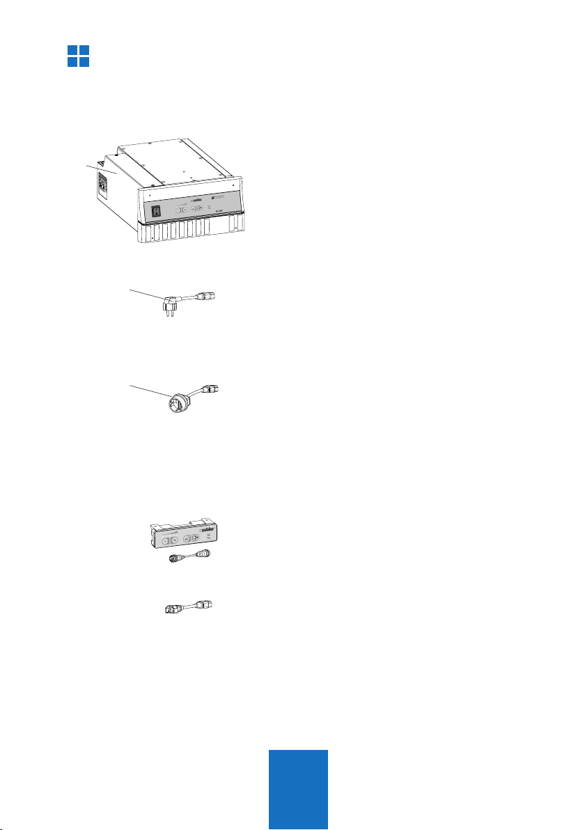
Zubler Z1 - AT User manual

Z1 - AT
Z1- AT
www.zubler.de
EN 02-2020
Single suction system

2
0. Intoduction page 4
0.1 Declaration of conformity
0.2 Intended purpose of use
0.3 Technical requirements
1.
Installation of the appliance
page 6
1.1 Scope of supply and accessories
1.2
Installation of the extraction system
1.3 Connection of working tools
1.3.1
Appliances without interface
1.3.2 Appliances with switching
output
(Potential free e.g. Relais)
1.4 Intake system
2.
Functional description
page 10
2.1 Control unit
2.2 Commissioning
2.3 Automatic operation
2.4
Selecting and saving suction levels
2.5 Current suction power
2.6 Setting the suction overrun time
2.7
Fine tuning of the automatic operation
2.8
Switching the extraction system off
Content

3
3. Maintenance page 16
3.1 Filter bag replacement
3.2 Replacement of the main filter
3.3 Motor
3.3.1 Motor replacement
3.3.2 Carbon brush replacement
3.3.3 Replacing the exhaust filter
3.4 Spare parts
4. Status Messages Seite 21
5. Technical Data Seite 23
6.
Garantie
Seite 24
7. Disposal instructions
Seite 25
Advanced settings are provided by the
Zubler Suction-Technology APP , which is
available for Android tablets or phones.
Therefore follow the users manual of the
Zubler Suction-Technology APP, which is
downloadable from www.zubler.de.
Suction-Technology

4
0.
We, Zubler Gerätebau GmbH
Buchbrunnenweg 26
89081 Ulm Jungingen
declare, that the product vacuuming unit
Z1 - AT
conforms to the health and safety
requirements set out in the directives
2014/30/EC EMV-Directive
2014/35/EC Low-Voltage Directive
2006/42/EC Machines Directive
Any modification not specifically approved
by us voids the validity of this declaration.
Kurt Zubler
ceo
0.1 Declaration of conformity
Introduction
Dear customer,
we are pleased, that you have decided for a Zubler extraction system and
hope it will enhance your work. The continuous development of our tech-
nology is based on the co-operation with experienced
dental technicians. The focus lies on the aim to optimize the extraction
technology in the fields of performance, noise and reliability.
Please read this operating manual carefully in order to ensure a prob-
lem-free operation.

5
0.2 Intended purpose of use
0.3 Technical requirements
Temperature: +5°C bis +40°C
Max. permissible relative humidity: max. 80% (bei 30°C)
Total connected load : 10A
This extraction system is designed exclusively for dry dusts!
Its use for the extraction of other types of dust or gases must be clarified
with the manufacturer before putting into operation.
Work must be stopped immediately and the system switched off in the
event of the appearance of visible clouds of dust or noticeably insufficient
suction power.
Inform your dealer or our service team.
The Z1 is designed for indoor use.
The volume of air circulated by the system and returned to the room may
not exceed 50% of the room air volume in closed rooms.
Use is restricted to persons who have been trained in its handling and are
authorised to do so. We reserve the right to make changes even without
updating this manual.

6
1.
2
3
1
Order.-No.
External control unit 823-020
2m cord incl.
Power adaptor C13/C14 012-00306
Installation of the appliance
1.1 Scope of supply and accessories
1x Z1 extraction system
1x Power cord
1x Power adaptor C14 / CEE
Special Accessories

7
7
8
6
5nBefore connecting the unit to the
mains power supply, check if the
voltage given on the number plate
corresponds with the local voltage.
n
The name plate with the Serial-No. is
located on the backside of the motor
unit 1 (Fig. 3).
1.2 Installation of the extraction system
1Z1- AT
2 mains power cord
3 power cord C13/C14
4 name plate
5 motor cover
6 electronic cover
7 main switch
8front cover
ZUBLER Gerätebau GmbH
Buchbrunnenweg 26
D-89081 Ulm
Tel. +49(0)731 1452-0 / www.zubler.de
Absauganlage
Z1-AT
Spannung 230V
Gesamtleistung max. 2000W
Absaugung max. 700W
Automatiksteckdose 1200W
Z1-AT 00-11111-22
Made in
Germany
nAttach the filter unit with the mounting
plate in the suitable height to the
backside of your cabinet.
nSlide the motor unit into the
designated cabinet of your workbench.
Take care, that meanwhile none of the
units feet is getting damaged.
Fig. 2
Installation requirementson
the cabinet
Fig. 1

8
11
10 9
14
13
12
4
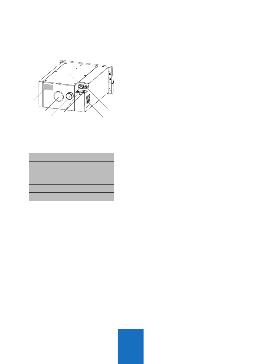
nPlug the enclosed power cord into the
IEC C14 connector 14 and the mains
plug into a local power socket.
(Fig. 3).
Mains connection
1.3.1
Devices without an interface
n
Use the IEC-Schuko power adapter
C14 -CEE included in the accessories to
connect your working device if it has a
permanently connected power cable.
n
If your work tool has an IEC connector,
you can alternatively order a suitable
cable C13 / C14 for direct connection
from the special accessories, item no.
012-00306. You then do not need the
associated power cord for your device
and the adapter.
The power consumption of this
device may be max. Be 1300W!
1.3.2 Devices with switching output
nIf your implement has a switching
output, a control cable (special
accessory) can be used to connect
to the extraction system. Use data
interface 13 instead of socket 12.
1.3 Connecting the working tools
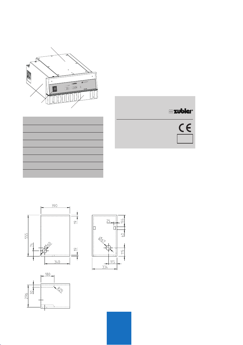
9fuses
10
vacuum nozzle
11 black plastic cover
12 autom. power socket
13 data interface
14 IEC receptical
Fig. 3

9
C
B
A
/
R1200
Basic system requirements include
optimal particle flow, minimal noise
production and ergonomic posture
promotion.
The following criteria promote these basic
requirements and are specifically adapted
to Zubler suction systems.
nSuction funnel R1200,
nRectangular pipe R1000, R1300
nRectangular silencer R1100
nThe R1200 suction funnel (21) was
tested according to GS-IFA-M20 test
no. 1305026 for a minimum suction
performance of 20 l/s.
nSitting in the upright position in a
posture preserving ergonomically
designed chair.
nWorkpiece as close as possible to
the suction funnel 21; no dust cloud
may be visible. Trails of dust must be
drawn into the hopper.
nDirection of viewing of the workpiece
perpendicular to the protective screen.
1.4 Intake system
A suction funnel R1200
B
rectangular pipe R1300
C rectangular pipe R1000
Fig. 4

10
T1 T2 T3 T4
L6
L4
L5
7
L2
L3L1
2.
L1 LED Power level display
L2 LED Bluetoothanzeige
L3 LED “ON”
L4 LED Filter
L5 LED Service
L6 LED “OFF”
T1 minus-button
T2 plus-button
T3 enter-button
T4 ON / OFF - button
7 main switch
nThe extraction system must be
installed and connected as described
in section 1.
nSwitch on the main switch 7.
nOne ore more LEDs of the suction
level L1 are flashing.
After approx. 5s the suction unit is
ready and the last saved suction level
is displayed. (At setup level 1).
nBy pressing the ON/OFF button T4 the
suction is started with the selected
suction level L1.
nIf changeing the suction level for the
first time, the unit will take some time
to calibrate the suction volume and
compensate the flow resistances.
nFor setting and saving suction levels,
see section 2.4.
Functions
Fig. 5
2.1 Control unit
2.2 Commissioning

11
-+
T1 T2
If a dust producing appliance is connected
to the extraction system, the sensitivity
must be adjusted for an automatic start of
the extractor.
The following steps are necessary in
order to teach the appliance:
nThe appliance (max. 6A, 120V:600W,
240V:1300W) must be connected to
the socket of the extraction system.
nPreselect the handpiece speed at
which the extraction system should be
started.
nStart the appliance or the handpiece
nd keep it running.
nWhile the appliance is running, press
and hold the buttons T1 (minus) and
T2 (plus) at the same time for at
least 3 seconds until a signal sounds
and the LEDs of the display L1 light
up. The extraction system will start
running for approx. 3 seconds.
nStill keep the appliance running.
nAs soon as another signal sounds
and the LEDs of the display L1 start
flashing, switch off the appliance or
stop the handpiece immediately.
nWait until a final signal sounds and
the LEDs of the display L1 show the
preselected suction level again.
2.3 Setting up automatic operation:

12
Level Z1-AT
1 20 l/s
2 23 l/s
3 26 l/s
4 30 l/s
5(„turbo“) max 35 l/s
T1 T2
-+
n
The suction levels 1 – 5 can be selected
with the T1 (minus) and T2 (plus) buttons.
nThe suction level shown on the display
L1 is the currently saved level with which
the extraction system switches on.
2.4 Selecting and saving suction levels
nPress the Enter button T3 to save the
new suction level
nIf the suction level is changed
without pressing the Enter button
T3, the extraction system will run the
lastsaved suction level the next time
the unit is started.
n
Suction level 5 (“Turbo mode”) is only
avail. for short time usage (factory set to
5 min.) and can therefore not be saved
in regulation mode.
n
While in “Turbo mode” the LED for
suction level 5 is flashing.
Once the time is elapsed, the suction
will fall back to the saved suction level
1-4.
n
Further adjustments can be made with
the Zubler Suction-Technology APP
(Android only).
T3
Suction-Technology

13
Mehrplatz - Einzelplatz (Anlage)
If the LEDs of display L1 light up
according to the selected suction level
during suction operation, this means that
the preset air flow rate of the suction
level is also actually being provided
and the motor has not yet reached its
maximum power.
If the desired air flow rate cannot be
attained (due to flow resistance or
filter clogging), then LED lights that are
solidsignify the attainable setting, while
the flashing LEDs signify the setting
and corresponding suction loss. The
volumetric flow control device is preset
in the factory so that a warning signal
sounds and the Filter Maintenance LED
L4 lights up only at minimum suction
power.
In the advanced settings (see section 3)
it is possible to set this so that the filter
warning is given as soon as the suction
power decreases to the next lower
suction level.
nFurther adjustments can be made with
the Zubler Suction-Technology APP.
2.5 Current suction power
Example:
Suction level 3 is
selected, but the air flow
rate
corresponds only to
level 2.
Suction-Technology

14
T1
-
T2
+
Mehrplatz - Einzelplatz (Anlage)
nPress and hold the plus button T2
for at least 3 seconds until only the
middle LED of display L1 is lit
nThe suction time can be reduced by 1
sec per LED jump to the left with the
T1 (-) button or increased by 1 sec per
LED jump to the right with the T2 (+)
button.
nPress the Enter button T3 to save the
new value
nPress the fan button T4 to abort the
procedure without saving
nThe suction overrun time can be
prolonged by a further 2 sec by
repeating the procedure.
n
Further adjustments can be made with
the Zubler Suction-Technology APP
(Android only).
2.6 Setting the suction cutoff time
For the extraction of the residual dust in the air, it is possible to extend the
time the extraction system should continue to run during breaks or after the
end of dust production. The factory setting is 3 seconds.
nPress and hold the minus button T1
for at least 3 seconds until only the
middle LED of display L1 is lit
nLower the switch-on threshold with
the T1 (-) button (extraction starts
earlier
nEasier; this is a solution if the
extraction system switches off or
doesn’t start-up immediately despite
dust being produced)
2.7 Fine tuning of the automatic operation
If the automatic sensitivity matching of the dust producer to the extraction
system has not yet led to an ideal result after section 1, the switch-on
threshold of the extraction can still be manually readjusted.
T3 T2
Mehrplatz - Einzelplatz (Anlage)
T1
-
Suction-Technology

15
T2
+
nThe switch-on sensitivity of the T2
(+) button (extraction starts later /
less easily; this is a solution if the
extraction system occasionally starts
up on its own or already runs in
standby).
nPress the Enter button T3 to save the
new value
nPress the fan button T4 to abort the
procedure without saving
nThe switching sensitivity can be set
even higher or lower by repeating the
procedure.
nSee section 3 for advanced settings
and troubleshooting.
The Z1 extraction system is intended only
for switched-on standby operation.
If the extraction system is switched off
or disconnected from the power supply, a
switch-off time of at least 10 seconds is
necessary.
If the extraction system is inadvertently
switched back on immediately, or in the
case of a short-term power failure of less
than 10 seconds, the system can enter
the error state. LED L5 lights up. In this
case the extraction system must remain
switched off for longer than 2 minutes in
order to be able to start it again.
Note! The Z1 extraction system cannot
be switched on and off by external
switching electronics that interrupt the
power supply to the extraction system.
2.8. Switching the extraction system off
T3 T2
Suction-Technology

16
Motor
556-0035
556-0034
556-004
556-0043
896-1205
896-1202
Filter
3 pcs.
M - Typ
C - Typ
C - Pack
Z1-AT
0,34kg
3.
1
3 4
5
2
Spare filter:
For your own safety, replace the filter bag or finefilter cartridge only with
appropriate protective equipment (filter mask, protective gloves and suit,
safety glasses etc.)
Store and dispose the contaminated filters immediately in a dust tight,
lockable container (e.g. plastic bag)
For an exchange of the filter bag proceed
as follows:
nSwitch OFF the suction unit with main
swich 7, also switch OFF the working
tool with its main switch to avoid an
accidential start.
nTurn the bolt fasteners on the filter
basket until they unlock and pull out
the filter basket (2)
nOpen the top cover (3)
nPull the filter bags gasket off the
nozzle. (4)
nSeal the opening with the adhesive
label located on the gasket.
nStore the filter bag immediately in a
dust-tight plastic bag.
nDispose the filter bag according to
your local regulations.
nInsert a new filter bag and slide the
gasket over the nozzle until stop.
nClose the filter basket with the cover.
nSlide the filter basket back into the
housing until stop and lock the bolt
fasteners. (5)
nSwitch ON the suction unit with main
switch 7 and also your working tool.
3.1 Filter bag replacement
Maintenance

17
Motor
556-0035
556-0034
556-004
556-0043
896-1205
896-1202
Filter
3 pcs.
M - Typ
C - Typ
C - Pack
Z1-AT
0,34kg
15
5
16
11
Spare filter: M - Typ
If the red LED display L4 „Filter“ lights up despite replacing the filter bag,
or if the replacement intervals become noticeably shorter, the reason is
usually that the fine filter is clogged with dust. To replace the fine filter
cartridge, proceed in the following order:
For an exchange of the fine filter cartridge
proceed as follows:
nUnplug the working tool from the
power socket.
nPull the motor unit out of the bench
and unplug the power cord from the
left, rear side of the suction unit.
nOpen the motor cover 5 by removing
the 8 countersunk screws TX20.
nRemove the black plastic cover 11 by
pushing with a screwdriver from the
inside.
nLoosen the knurled screw 15 until the
fine filter cartridge 16 can be taken out
to the top.
nStore the fine filter immediately in a
dust tight, lockable plastic bag.
nDispose the fine filter according to
your local regulations.
nInsert a new fine filter cartridge and
tighten the knurled screw 15 firmly.
nPress the black plastic cover back into
the housing and close the motor cover
with the 8 countersunk screws TX20.
nConnect the power cord and slide the
unit back into the bench.
nPlug the power cord of the working
tool into the power socket.
Fig. 6
3.2 Replacement of the main filter
5motor cover
11 black plastic cover
15 knurled screw
16 main filter

18
5
17
18
3.3 Motor
Due to our innovative motor control, the
wear of the motor and the carbon brushes
is reduced significantly. Resulting in a
maintenance-free runtime of 1500h.
Moreover the carbon brushes can be
changed more often, enabling a total
motor lifetime.
The lifetime depends strongly upon the
operating mode (Suction level, Filter filling
grade).
3.3.1 Motor replacement
nUnplug the power cord from the
suction unit and working tool.
nPull the suction unit out of the bench.
5motor cover
17 motor clamp
18 motor connector
19 motor
21 sealing plate
23 carbon brush holder
Fig. 7
Fig. 8
Caution!
Ensure that the unit is disconnected
from the mains power supply!
After unplugging the mains power
supply, wait at least 2 min. before
proceeding with the replacement of
the motor.
nOpen the motor cover 5 by removing
the 8 countersunk screws TX20
nDisconnet the motor connector 18 by
pressing the latches and pulling out
the plug.

19
19
21
23
19
Fig. 9
nSlide the motor module to the front
and remove it to the top.
nInsert the motor vice versa.
nTake care, that the motor module is
inserted on the very front first and
must be slided backwards to the
sealing plate 21.
3.3.2 Carbon brush replacement
nThe motor package has to be removed
in order to replace the carbon brushes!
Using a blunt object, press the metal
tongue downwards (fig. 10) and pull
the carbon brush holder out. Now
push in the carbon brush (see 3.4
Spare parts) until it engages and
mount everything in the reverse order.
Always replace both carbon brushes!
The remaining length of the brushes
may only be up to 50% after expiry of
the time. Further use is not worthwhile
and can lead to destruction of the motor
collector.
Fig. 10

20
22
20 6
Order no.
Filter bag 556-003
Filter bags 3pcs. 556-0035
Fine filter M-type 556-0034
Activated carbon filter Z1-M C-type 556-004
Activated carbon refill pack Z1-M 556-0043
Carbon brushes + fleece 220 – 240 V 896-1202
100 – 120 V 896-1201
Motor module 220 – 240 V 896-1205
100 – 120 V 896-1204
3.4 Spare parts
3.3.3 Replacing the exhaust filter
The exhaust filter must be replaced with
every exchange of carbon brushes, since
the filter material can not absorb the the
debris of multiple brushes.
nFor a replacement of the exhaust filter
22 proceed as follows:
nOpen the exhaust cover 20 by
removing the 4 screws TX20.
nTake out the exhaust filter carefully
and clean the inside with a vacuum
cleaner.
nInsert the new exhaust filter into the
exhaust cover that the blue side is
visible. Take care, that the cut outs are
aligned with the mounting holes.
nAttach the exhaust cover to the motor
housing with the 4 screws TX20.
20 exhaust cover
22 exhaust filter
Table of contents
Other Zubler Medical Equipment manuals
Popular Medical Equipment manuals by other brands

Otivio
Otivio FlowOx 2.0 quick guide

laerdal
laerdal SimMom Directions for use

bort medical
bort medical ActiveColor Sport Wrist band with thumb... manual

SIMS Deltec
SIMS Deltec CADD-1 5100 HFX Operator's manual

Health Care Logistics
Health Care Logistics Lock Assembly instructions

Otto Bock
Otto Bock Agilium Freestep 3.0 Information for users