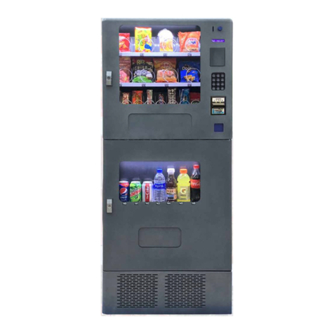
Zummo Z10 User manual

011243/01
Z10
INSTRUKCJA OBSLUGIINSTRUKCJA OBSLUGIINSTRUKCJA OBSLUGI

English Pag. A - 1
ايبرعل Pag. B - 1

A - 1
ZUMMO INNOVACIONES MECÁNICAS, S.A., in an ongoing effort to enhance its products, reserves
the right to modify machines without prior notice; for this reason, this user’s manual may not contain
the latest changes made.
IMPORTANT SAFETY INSTRUCTIONS
The machine is not suitable for outdoor use; it should not be exposed to direct
sunlight or located anywhere that is unprotected from weather conditions or
places where water jets are being used for cleaning purposes.
Do not clean the machine with direct jets of water or water at high pressure.
To avoid risks, any repairs must be carried out by technical staff.
No responsibility is accepted should damage be caused through misuse of the
machine and not having followed the instructions in this manual.
Request technical assistance from the company that supplied the machine. If not
located, please contact the factory (information on the cover of this manual).
The squeezing machine uses a great deal of pressure when extracting the juice;
therefore, never introduce hands or foreign objects into the squeezing area.
Never leave the FASTENING NUTS loose as this may cause serious damage to
the machine.
Take special care with the BLADE, as this may cut you when being handled.
Always unplug the machine from the power supply before cleaning or
maintenance.
If the power cable is damaged, it must be replaced by the manufacturer either by
its after-sales service or by similarly qualified professionals to avoid danger.
The machine is equipped with rear buffers which guarantee a minimum space for
ventilation but, even so, a minimum gap of 10 cm is recommended between the
back of the machine and the nearest wall to ensure adequate internal ventilation.
The air inlet and outlet should not be obstructed.
If the machine is to be encased in a closed cabinet, inlet and outlet ventilation
holes should be provided and the cabinet equipped with a forced ventilation
system.
The machine should not be used by children younger than 8 years old, anybody
with impaired physical, sensory or mental capacities, or those lacking in
experience and knowledge, unless they are supervised or have received training.
Children should be supervised to ensure they do not play with the machine.
Cleaning and maintenance that is the responsibility of the user should not be
undertaken by unsupervised children.
Do not store explosive substances such as aerosol cans with a flammable
propellant in this appliance.
Manual available at:http://www.zummo.es/uploads/011243-01-Manual-Instruccion-Z10.pdf

A - 2
CONTENTS
1. INTRODUCTION A - 3
1.1.TECHNICAL DATA A - 3
2. WASTE AND RECYCLING A - 3
3. GUARANTEE A - 4
4. PHOTOS C - 1
SERVICE MANUAL
1. LOADING AND CLEANING (chapter 1) A - 6
1.1.ORANGE LOADING A - 6
1.2.GLASS LOADING A - 6
1.3.CLEANING A - 7
1.4.ADVICE FOR USE A - 8
1.5.SIGNALS A - 8
MAINTENANCE MANUAL
1. INSTALLATION, PROGRAMMING AND MAINTENANCE (chapter 2) A - 10
1.1.UNPACKING A - 10
1.2.INSTALLATION A - 10
1.3.INITIAL START-UP A - 10
1.4.PROGRAMMING A - 11
1.5.AUTOMATIC CLEANING A - 13
1.6.COLD ADJUSTMENT A - 13
1.7.SAFETY SYSTEMS A - 13
1.8.MAINTENANCE A - 14
1.9.TROUBLESHOOTING A - 14
1.10. LIST OF COMPONENTS A - 16
2. ACCESSORIES A - 19
2.1.SOLENOID VALVE CONNECTION FOR WATER ENTRY AND DRAINAGE A - 19
2.2.COIN BOX CONNECTION A - 20
3. DIAGRAMS
4. STRIPPING PLANS

A - 3
1. INTRODUCTION
Zummo Z10 is a vending machine orange juicer, so should only be used to squeeze oranges.
This document is an integral part of the machine and, as such, should always accompany it in
any change of ownership or company move.
Before installing and using the product it is essential to read the content of this document as it
provides important information regarding its safe installation, correct use and maintenance
procedures.
The manual is divided into two chapters. The first chapter describes the routine loading and
cleaning of the machine and the second chapter contains instructions for the correct installation,
programming and maintenance of the machine. These procedures must be performed only by
qualified staff and/or professionals contracted to provide technical and/or maintenance support.
The machine should only be used for the purpose for which it was intended. Any other use will
be considered as improper.
The machine is sold without a payment system and therefore any malfunction or damage to
people or equipment that is shown to be a consequence of the installation or incorrect use of a
payment system will be the sole responsibility of those who installed the system.
1.1. TECHNICAL DATA
MAXIMUM
POWER
SQUEEZER (W)
390
LOADER (W)
300
COLD UNIT (W)
750
LIGHTING (W)
3.2
STORAGE CAPACITY (kg.)
50
SIZE
HEIGHT (cm)
183
WIDTH (cm)
100
DEPTH (cm)
68
ENVIRONMENTAL
LIMITS
TEMPERATURE BETWEEN
+5ºC and +50ºC
HUMIDITY BETWEEN
45% and 70%
WEIGHTED SOUND PRESSURE LEVEL “A”
Less than 70 dB
WEIGHT (kg.) (unpacked)
298,5
COOLANT GAS LOAD Type R-134A (kg)
0.30
VOLTAJE AND ELECTRICAL FREQUENCY
Ref. Z10A
230V-50Hz
Ref. Z10B
220V-60Hz
Ref. Z10C
110V-60Hz
VOLTAGE AND FREQUENCY........................................... See the registration plate. (Fig. 7).
2. WASTE AND RECYCLING
Out of use equipment
European Union
This symbol indicates that electric and electronic equipment bearing it must
not be disposed of together with general domestic rubbish. If you wish to
dispose of this equipment, do not use normal rubbish bins! There is a special
collection system for these products.

A - 4
To obtain further information in the collection and recycling of such products, contact your
municipal waste disposal service, your waste disposal manager or the distributor that sold the
product.
If you correctly dispose of the product, you will be helping to conserve natural resources
(recovery of materials) and in preventing possible harmful effects to the environment and
personal health, which might be caused by incorrect treatment of the waste product.
Inappropriate disposal of this waste may involve sanctions, depending on the national
legislation.
Other countries not belonging to the European Union
If you wish to dispose of this product, do so in accordance with the national legislation in force
and other regulations in your country concerning the disposal of used electric or electronic
equipment.
Packaging
To dispose of it, bear in mind the local regulations for the treatment of this kind of waste.
Separate the different waste packaging materials and deliver them to the nearest selective
collection point.
3. GUARANTEE
ZUMMO INNOVACIONES MECÁNICAS S.A., through its official distributor, guarantees their
machines for a period of 3 YEARS or 70.000 servings, valid from the date of delivery to the
distributor, in accordance with the following conditions:
This guarantee covers all material or manufacturing defects.
If any faults are found during normal use and within the guarantee period, the defective parts
will be replaced free of charge.
Repair or replacement of machine parts during the guarantee period, does not imply and
extension in guarantee expiration.
The guarantee shall be valid only when presented with the original purchase invoice.
The original parts are covered by a six-month guarantee.
This guarantee does not cover
Any damages not directly caused by a fault of manufacturing or materials.
Any damages due to incorrect installation, abuse, improper use, modifications, accidents or
negligence.
Any parts scratched due to use of improper washing.
The distortion of heat-formed plastic parts, listed at the end of section 13, due to exposure to
excessively high temperatures.
Labour not covered by this guarantee.
Any damages caused by unauthorised staff or materials.
Any defects caused by use wearing down; in individual the following component:
0505016 PEEL EXTRACTING BANDS.
Technical assistance
In case of damages caused during the guarantee period, we suggest you contact the
Authorised Dealer who supplied the unit, or call ZUMMO:
E-mail: sat@zummo.es
Tel: +34.96.1301246
Fax: +34.96.1301250
Any repairs not authorized by ZUMMO during the guarantee period will cause immediate
termination of the guarantee.

A - 5
SERVICE MANUAL

A - 6
1. LOADING AND CLEANING
Access to the service area is only permitted to people with the appropriate training and
knowledge to load and clean the machine, especially regarding matters of hygiene and
safety.
Machine operators are responsible for their personal hygiene and cleanliness in compliance
with current health and safety regulations.
The product offered by the machine is citrus juice with a pH not higher than 4.5; therefore it
not considered a potentially hazardous food.
Cleaning must be undertaken using a detergent suitable for foodstuffs which does not
require rinsing with water. Product dosage should follow the amounts specified in the
technical data sheet.
It is advisable to use soft water for cleaning the machine.
It is advisable to turn off the main switch of the machine before starting any cleaning
procedures. Do not clean the machine with direct jets of water or water at high pressure.
We recommend a thorough wash of the parts that are in the squeezing area unless once a
week (CUPS, INTERIOR FILTER, SQUEEZING TRAY, BLADE and SQUEEZER FRONT
COVER), MACHINE DOOR, DRIP GRILLE, EXTERIOR FILTER and EXTERIOR FILTER
TRAY following the cleaning instructions.
1.1. ORANGE LOADING
The machine is prepared to squeeze oranges with a diameter of 55 to 75 mm. (with the set
of green cups and balls), if you wish to squeeze oranges with a larger diameter, use red
cups and balls that allow oranges with a diameter of 70 to 90 mm. to be squeezed.
45 to 50 kg. fit on the loader (Scheme 1, No. 14), depending on the type of orange.
Every time the machine is loaded, ensure that an orange is placed in the left hand cup
(Scheme 1, No. 8).
ATTENTION!: Do not excessively fill the hopper. There must be a gap of at least 15cm.
underneath the rollers (Fig. 17). If you fill it over this level, when the oranges rise, the rollers
may come out of their housing and the machine will signal a fault and will become out of
service. (Fig. 18).
Do not fill with oranges in bad condition.
1.2. GLASS LOADING
Ø70 glasses must be placed in the glass loader (Fig. 19), which may have different
capacities of 150, 220 or 250cc with Ø73*.
120 to 140 glasses fit, depending on the manufacturer and glass capacity.
We recommend the use of antistatic treated glasses.
The colour of the glasses is indifferent.
You can test the working of the glass loader manually by pressing button S4 on the control
plate.
ATTENTION!: Please observe that the glasses are not oval nor are they excessively stuck
together.
* Optional accessories, not included as standard

A - 7
1.3. CLEANING
SQUEEZING AREA:
Dismantling:
- Unscrew the nut holding the FRONT COVER, (Fig. 20) remove the FRONT COVER
and clean it with a cloth and soapy water. (ATTENTION!: Do not use abrasives
and NEVER clean with product that may scratch).
- The SQUEEZING TRAY and the BLADE are removed by unscrewing the nuts from
the SQUEEZING TRAY SHAFT and pulling out sideways. Also unscrew the
GREEN BALLS inside the SQUEEZING TRAY (Fig. 21); under each one are one
washer, be careful not to lose them! When cleaning TAKE SPECIAL CARE
WITH THE BLADE (Fig. 5), as it is very sharp and you may cut yourself.
- To remove the CUPS, unscrew the FASTENING NUTS slightly and push them
down and pull outwards. They will become lose and can be easily removed.
- Remove the fallen peel. (Scheme 1, No. 15).
- Wipe the FRONT and ROOF of the squeezing machine with a cloth and soapy
water.
Assembly:
- Screw the BALLS onto the SQUEEZING TRAY. Be careful to replace the washer
beforehand and to screw the BALLS tightly into position.
- Check that the BLADE has its PEEL EXTRACTING BANDS correctly positioned
(the Extracting Band parallel to the FRONT of the machine must be above the
perpendicular Extracting Band see (Fig. 22)) and place the BLADE into the
SQUEEZING TRAY. Assemble the unit (SQUEEZING TRAY + BLADE)
simultaneously on the three machine Shafts. (Fig. 23). Never assemble the
BLADE onto the tray afterwards!! When it reaches the bottom, fit the BLADE lip
onto the front guide. (Fig. 24).
- Place the Cups onto the Shafts and tighten using the nuts.
- Before restarting the machine, observe:
That the Squeezing Tray and the Blade are well fitted and screwed in tightly.
That the BLADE is well fitted and in a horizontal position.
That the Cup Nuts are well tightened.
- In the event of the BLADE, the Squeezing Tray, the balls or the cups not being well
placed, damage may be caused to these parts and even to the inside of the
machine. (Problems not covered by the guarantee, these being operator faults).
WASTE BAG. - The waste bag must be replaced unless every 48 hours. (Fig. 25)
MACHINE DOOR.-To keep the door rubber seal in good condition, it is very important
to clean it frequently. Also remember to keep clean the lower part of the machine’s door
to prevent proliferation of unwanted insects.
WATER CONTAINER. - Empty the WATER CONTAINER (Scheme 1 No. 17) and place
it back. Place the WATER LEVEL SENSOR above the mouth and the EVAPORATOR
DRAIN HOSE and HYDROTUBE in its holes.
DRIP GRILLE. -Unscrew the plastic nut and pull backwards to remove the Drip Grille.
(Fig. 26). The Drip Tray can be unscrewed should it require thorough cleaning.
EXTERIOR FILTER and EXTERIOR FILTER TRAY. -Loosen the handles fastening
this unit, (Fig. 27) pull the right hand side upwards and then to the right until completely
loose. Remove the filter and its tray, paying attention to the original position. After
washing, replace it and tighten the handles slightly. Attention! Never use hot water to
wash the exterior filter tray, it will get distorted!
FEED ROLLERS. -When you want to wash the Feed Rollers, these can be removed
from their housing. To do so, pull the left hand side upwards and then to the left. (Fig.
28 and 29). If the coils are removed, pay attention to their position because each roller
has one on each side.
A - 8
IMPORTANT: Refs. 1003005A left channel, 1003007A right channel, 1003024B front
cover, 1003025 exterior filter tray and 1004023 lower plastic lid, are made from heat-
formed plastic. They must not be subjected to temperatures higher than 40°C, so they
should never be washed in very hot water or in a dishwasher; if they are deformed by
heat, the warranty will not apply.
1.4. ADVICE FOR USE
Do not use the gap in the hopper for storage (Fig. 37).
Make sure not any objects block the drainage tube. (Fig. 38)
Make sure the oranges fit easily into the cups chosen for squeezing, because if the cup
is too small it will pinch the peel and draw out oil which will make the juice taste bitter.
To get the maximum amount of juice, it is better for the cups not to be too much bigger
than the oranges being used.
Clean the photocell lenses regularly.
1.5. SIGNALS
“NO CHANGE” SIGNAL
This is programmed from the coin box, depending on each manufacturer. In most cases, if the
machine has no change, it will only accept coins that go to return tubes.
“NO ORANGES” SIGNAL
If the photocell on the right of the roller conveyor sees no oranges (Fig. 40), it starts the loader
and this is stopped when it sees oranges fall. If, however, the loader is working for 1 minute and
the photocell continues to see no oranges, it signals “no oranges” and the machine becomes
out of service.
“NO GLASSES” SIGNAL
When the service is started, the process is as follows: The glass loader (Fig. 19) releases a
glass and if the glass photocell (Fig. 39) sees no glasses, it repeats the operation three
times and, if it continues to see no glasses, it signals “no glasses” and the machine
becomes out of order.
“WITHDRAW GLASS” SIGNAL
Whenever there is something in front of the glass photocell (Fig. 39), this signal is lit up.
“SELF-CLEANING” SIGNAL
This signal is lit up during the cleaning and draining process.
“FAULT” SIGNAL
This lights up in the following cases:
- If, during a service, the oranges get stuck on the rollers and the squeezing machine
carries out 5 cycles without any oranges reaching the MAGNETIC SENSOR (Fig. 31).
- If, when starting or finishing a service, the glass conveyor, (Fig. 32) on its run, takes
over 8 seconds to reach the end of the run.
- If the squeezing machine (Scheme 1, No. 5) is blocked by something.
- If at any time the squeezer safety circuit is opened, which implies leaving the
SQUEEZING TRAY out of place or tripping the motor heat switch.

A - 9
MAINTENANCE MANUAL

A - 10
1. INSTALLATION, PROGRAMMING AND MAINTENANCE
It is compulsory for the machine to be earthed to avoid the possibility of people being given
shocks or damage to the equipment.
In all cases, the machine should be connected in compliance with local and/or national
regulations and legislation.
The machine should be powered via a differential switch (RCD) not exceeding 30 mA.
It is advisable to ensure that the mains power distributor is equipped with a disconnect
device with a contact separation of at least 3 mm.
The plug must be easily accessible once the installation is complete. The use of extension
cables, adaptors and multiple sockets is not permitted.
These procedures must be carried out only by personnel with specific knowledge of the
machine in terms of electrical safety and health regulations.
1.1. UNPACKING
Raise the machine and withdraw the metal supports using a No. 24 spanner (Fig. 1).
Screw the supports into the holes where the packaging screws were located (Fig. 2).
The height between the base of the machine and the ground must be approx. 90mm.
Open the door and remove the wooden strips that are merely for transportation purposes.
(Fig. 3).
Remove the adhesive tape holding the movable elements in place.
Remove the expanded Polystyrene holding the machine. (Fig. 3A)
1.2. INSTALLATION
Position the machine in an aired place away from rain and heat sources (heaters, sunrays,
etc.)
Level the machine by manipulating the supports until it is in a fully horizontal position and
the door fits perfectly. (Fig. 2).
Keep the machine upright one hour before connecting so that the compressor oil returns to
its original place and is not damaged.
Leave a gap of 10 cm behind the machine to ventilate the Cooling Unit and do not place
anything below it. (Fig. 6)
Before connecting to the mains, ensure that the machine voltage and frequency coincide
with your electrical installation. See the registration plate. (Fig. 7).
Use a socket with an efficient earth protected by a 0.03A trip switch and a general switch.
The machine must be installed in a place with good ventilation.
The machine is not prepared to be installed outdoors.
Before switching the machine on it is advisable to clean all the parts that will come into
contact with the juice, i.e. the cups, filter, tray, blade, squeezing tray, balls and cover.
1.3. INITIAL START-UP
A. Leave your ZUMMO Z10 in an upright position, without working, for one hour.
B. Activate the green switch (Scheme 1, No.18).
C. Fill the WATER CONTAINER (Scheme 1, No. 2 with drinking water and introduce the
suction pipe to the bottom.
D. Ensure that the evaporator waste pipe (Scheme 1, No. 16) is positioned so that the waste
water falls into the WASTE WATER CONTAINER (Attention: During the orange loading or
machine cleaning process, in which the machine door is open, it is normal that some water
may fall).
E. Place the WATER LEVEL SENSOR hanging above the mouth of the WASTE WATER
CONTAINER (Scheme 1, No. 17) (Fig. 10) (This sensor serves as a ballcock so that the
waste water does not overflow).

A - 11
F. At the inner top left of the machine is a Door Switch (Scheme 1, No. 10) with three
positions:
- “Sunken” with the door closed: There is communication between the control panel and
the coin box and if there are no oranges on the rollers these and the hopper loader will
begin to work automatically. (Scheme 1, No. 13 and 14)
- “Free” with the door open: Nothing working automatically and no communication
between the control plate and the coin box, although the control plate buttons are
working.
- “Stretched” with the door open: The same function as sunken with the door closed.
Useful during the loading operation, as the loader and rollers can be filled, using
machine capacity to a full.
1.4. PROGRAMMING
FUNCTION OF THE CONTROL SWITCHES
The control panel switches (Scheme 2) (that work with the door switch “free”) have the
following functions:
S1. Programming field selection.
S2. Modifying field selection.
S3. Water pump.
S4. Cup loader activator.
S5. Cup conveyor motor –backwards.
S6. Cup conveyor motor –forwards.
S7. Free sale (with door switch “stretched”)
S8. Squeezing machine.
S9. Orange conveyor rollers.
S10.Loader
S11.Compressor unit.
PROGRAM SETTING ACCESS LEVEL 1
To enter to program, you must have the door switch in “free” position (Scheme 1 No. 10) (Door
open, the display will show 4 dashes).
By S1 and S2 you will have access to: see the counter of cups sold, set the number of oranges
to squeeze per cup and the sale price per cup. The display (Fig. 30) will show the following
fields:
Fields 1 and 2: Meter.
Activate switch S1 to access the first field.
Field 1 displays sales from 1 to 9,999.
Field 2 displays the number of entire cycles of Field 1.
To pass from one field to the next, activate switch S1.
Field 3. Number of oranges per serving.
Press S1 again to access the third field, where the number of oranges to be squeezed per
serving can be selected. A message 3 4 will appear on the screen, which means that you
are in field 3 and 4 oranges per serving have been selected. If you want to modify the
number of oranges, press button S2 until the desired number is shown.
Field 5. Serving price.
Switch S1 leads to field 5 and a message 5020 appears on the screen. This means that the
price is “20 base coins” per serving (in Spain, the base coin normally programmed on coin
boxes is 5 cent.). By intermittently pressing button S2, the price increases and when held
down, the price decreases.

A - 12
PROGRAM SETTING ACCESS LEVEL 2:
To enter program setting level 2 please do the following: With the door open (dashes on the
display), pull the door switch towards you (Scheme 1 No. 10) and when the on the display
shows numbers instead of dashes, press S1 (Scheme 2) and hold, return the door switch to its
normal position (middle position) and release S1.
Fields 1 and 2: Meter.
The same as in the first access level.
Field 3. Number of oranges per serving.
The same as in the first access level.
Field 5. Serving price.
The same as in the first access level.
Field 6. Type of coin box.
Press S1 to pass to field 6 and the screen 6 0 will appear. This means that the coin box to
be installed is Executive. If you press S2 again, it will change to 6 1, which means that the
machine will communicate with an MDB coin box.
Field 7. Stopping position the cups. (Scheme 1 No. 8)
After having used the machine for a while, it is likely that the cups in the squeezing unit will
not stop at upright position, and lean slightly inwards.
To ensure the cups stop vertically, press switch S2 until you lower the number that initially
appeared one or two units. So, when modifying this value, the cups will stop a Little forward
or a Little backwards.
Field t. Operating temperature
Press S1 to enter field “t” it will appear t12º on the display. This means that inside the
machine there will be a temperature between 6 ºC and 12 ºC. Press S2 to modify the
temperature from 10 ºC to 50 ºC.
Field 8. Duration of the automatic washing.
Entering field 8 you can select the how many seconds will last the automatic washing from 7
to 20 seconds.
Field 9. Enable Sale Button
Entering field 9 you can set sale button (only those versions where the button is installed)
There are 3 options available:
9__0: the button is disabled
9__1: the machine will operate after having completed the credit and only when the button
is pushed
9__2: the machine will operate once the button is pushed (no need to insert any credit).
Fields A, b, c, d, e.
Fields A, b, c, d, e are used only when a MDB Notes Reader has been installed. The five
fields are used to set the value of the notes.
In order to set the value of each note, please remember that you have to use the Coin
Operator multiplier (value of the base unit given by your Coin Operator). In case your MDB
Notes Reader has its own multiplier, please disregard it.
Example:
US $ Coin Readers normally have as base unit (multiplier) the number 5 (= 5 cents coin).
But the US $ MDB Notes Readers use as base unit (multiplier) the number 1 (= 1 US
Dollar).
To set the value of the 1 US $ and 5 $ US notes in the Notes Reader:
1 $ = 100 c (cents)
5 $ =
100 c c
5 c per base unit
1 $ =
=20 ( b.u ) base units
500 c c
5 c per base unit
= 100 ( b.u ) base units

A - 13
Note: In case you wish the machine to work only with your MDB Notes Reader (without
Coins Reader), please ask the factory.
ERASE ALL SET VALUES: By entering field 9 and pressing S7, all the values set in the
machine will be erased.
DOOR SWITCH: When you open the door, a safety switch cuts the communication to the
electronic circuit board of the machine. To simulate the operation of the machine with the door
open, pull out the door catch and check whether there is any communication with the control
panel.
TAKE SPECIAL CARE WITH MOVING PARTS SUCH AS THE LOADER, THE ROLLERS,
THE BLADE AND THE FILTER CLEANER.
1.5. AUTOMATIC CLEANING
The machine is equipped with a self-cleaning system that consists of:
a) A suction nozzle, located on the roof of the squeezing machine that rinses the
BLADE and its blade. (Fig. 11).
b) Two nozzles located inside the SQUEEZING TRAY that rinse the orange pulp
accumulated inside. (Fig. 12).
These three nozzles start working every time that one of these circumstances are brought
about:
1) 10 juices have been made without over 45 minutes having gone by between two of
them.
2) 45 minutes have gone by since the last juice.
3) After cleaning corresponding to case 2, 4 hours have gone.
To carry out this task, the machine has:
A water container (Scheme 1, No. 2), located behind the waste bag, that must be
filled with drinking water. Once full and placed in its position, introduce the rubber
water suction pipe sticking out of the container to the bottom.
The water used for cleaning and from condensation falls into the WASTE WATER
CONTAINER.
1.6. COLD ADJUSTMENT
In programming field “t”, the temperature required from 10° to 50°C can be chosen (50° for
when the compressor is never to be connected). We recommend it be programmed between
10-12°C.
The Cooling System works in the following manner:
- The evaporator ventilators are always operating.
- With the door open, the compressor is always at a standstill.
- When the door is closed, if the inside temperature is equal to or above that
programmed, the compressor will start up after two minutes.
- The maximum running time of the compressor is 30 minutes. If this time is exceeded
and the stoppage temperature has not been reached, (six degrees below that
programmed), the compressor will stop for 8 minutes for defrosting and will then start to
run again until the stoppage temperature is achieved.
1.7. SAFETY SYSTEMS
The machine has various safety systems:
If, during a service, the machine becomes out of order, the Coin Operator returns the
money introduced.
If the Squeezing Tray and the Blade are not well positioned and their Fastening Nuts

A - 14
are tightened, (Fig. 33) the squeezer will not work and the display will show a fault.
If, for some reason, the squeezing machine, when working, becomes blocked, after a
few seconds the motor will automatically stop and the display will show a fault.
The machine has heat protection systems in the Squeezer Machine and Loader motors
that, in the event of overheating, stop working. In the case of the Squeezer Motor the
DISPLAY will show Fault. In case the Loader Motor the Loader simply will stop.
The glass conveyor motor is protected in such a way that if the conveyor moves and
after 8 seconds the Cup Transporter has not reached the end of its run, the motor stops
and the display shows a fault.
There are two 6.3A 6,3x32 mm fuses on the control panel (Scheme 2) that protect the
low voltage circuit.
A general fuse 10A 6,3x32 mm (Scheme 1 No. 9)
1.8. MAINTENANCE
Squeezer Machine: Grease the roof hinge occasionally. (Fig. 34). (Thick grease –
consistency grade 2 DIN 51818 and distilled water grade 0 corrosion resistance).
Glass conveyor: Grease the guides (Fig. 35 and 36) (water repellent grease).
Attention! Do not use aerosol lubricants, as these would grease the belt, causing it
to slip.
Cooling Unit: Clean the ventilation grilles (Fig. 42).
Loader: Grease the upper and lower bearings. (Thick grease –consistency grade 2
DIN 51818 and distilled water grade 0 corrosion resistance).
1.9. TROUBLESHOOTING
GLASS CONVEYOR: (Fig. 32, 35, 36).
- Check that the drive pulley does not slip on its axis. Should this be the case, tighten the
fastening stud on the pulley.
- Check that the belt does not slip on the drive pulley. Should this be the case, tighten the belt
or apply a non-slip product.
- Check that the photocell led turns on and off when the glass is placed in front of it. Where
necessary, clean the lens (Fig. 39).
- If glasses are on the lower stool, probably is because they have an oval shape. Please
store the glasses so that they are not misshapen.
CUP DISPENSER: (Fig. 19).
- If the “No Glasses” signal appears when there are glasses, It means that the Cup Dispenser
tried three times to dispense a glass but none have fallen. Check that the glasses are not
overly stuck together or misshapen.
LOADER AND ROLLER CONVEYOR: (Scheme 1, No. 14 and 13).
- If the loader does not start, despite there being no oranges on the rollers, check that the
rollers photocell led turns on and off by bringing your hand towards it. Where necessary,
clean the photocell lens (Fig. 40).
- Check that the left end of each roller is in its correct position (Fig. 28). If the rollers have
come out of their housing, then the orange tank may be too full (Fig. 18).
COOLING SYSTEM:
- If there is condensation inside the machine, this implies it is colder outside the machine than
in. This is because the thermostat is adjusted to a temperature that is too high. In winter, the
temperature should be lowered to avoid this. It may also be that the ventilation grilles are
obstructed. Pull the machine away from the wall.

A - 15
- Remove the ventilation grilles and check: a) the compressor unit ventilator that must always
be working when the compressor is working (Fig. 41). b) That the condenser air inlet is not
dirty (Fig. 42).
- The compressor is loaded with gas R134A gas. R134A gas is no harmful to the ozone layer.
If at any time the load is required should be always with R134A gas (300 gr) and this
operation must be performed by agents specialized in industrial refrigeration.
SELF-CLEANING SYSTEM:
- Check that the water suction pipe is pushed to the bottom (Scheme 1, No. 3).
- Check that the Water Level Sensor is in position and that works correctly (Fig. 10).
- Check that the water pump are working by pressing button S3 (Scheme 2). (Remember to
place the door switch at “free”). (Sect. 6, point F)
- If the water pump is being used and when button S3 is pressed a characteristic noise is
heard but the water does not reach the nozzles, dismantle the water pump and clean the
rubber membrane, which is bound to contain a small stone of some kind.
COIN OPERATOR:
- Check that field 6 is programmed for the type of Coin Operator installed.
For any queries or a request for response, please indicate your machine number
(Fig. 7)

A - 16
1.10. LIST OF COMPONENTS
Code
Description
0502004
BLADE SLIDE COVER
0502005
CUP SLIDE COVER
0503001
FEED PADDLE
0503003
FEEDER LEVER SHAFT
0503004A
FEEDER LEVER
0503005A
FEED PADDLE ROD
0504001A
GEAR BOX TYPE SX-50 i=36:1 (BOX)
0504002B
MOTOR 0,33CV 225v 50Hz
0504003B
MOTOR BIPHAS 0,33CV 110V-60Hz (FEET)
0504003C
MOTOR BIFAS 0.33CV 220v-60hHz
0504005
GEAR BOX POLEY (60XL 037)
0504006
PINION
0504007
BOLT & PINIONS WASHER
0504008
RACK
0504009
BOLT (UPPER CONNECTING ROD)
0504010
CONNECTING ROD
0504012
RACK SLIDE
0504013
PRESS PLATE FASTENER
0504014-1
CUP SLIDE
0504015A
BLADE SLIDE
0504016
CUP SLIDE BAR
0504019
BELT 190XL 037
0504020
PLASTIC WASHER 7,5/15 X 1,5
0504026
SHAFT (GEAR BOX SX-50)
0504A00
PRESS SET
0504B00
BLADE SHAFT
0504B04
BLADE SHAFT COTTER
0505003G
BLADE Z05 (GREY)
0505004G
BALL 80 (BRIGHT GREY)
0505005G
BALL 67 (DARK GREY)
0505006G
CUP 90 (BRIGHT GREY)
0505007G
CUP 75 (DARK GREY)
0505009A
CUP SHAFT
0505010A
FASTENING NUT WITH RAKED JOINT
0505010A-1
CUP NUT
0505010A-2
FASTENING NUT JOINT Ø20
0505011A
SQUEEZING TRAY SHAFT
0505016
PEEL EXTRACTING BANDS
0506002B
MICRO-COUNTER HOLDER
0506006/1
SQUEEZING TRAY MICRO CLAMP
0506007
MICRO (SHORT)
0506008
MICRO (LONG)
0506011
FUSE Ø5X20 6A
0506023
ELECTRIC LEAD (UL-CSA Standard)
Code
Description
10/10
SWITCH + LED LIGTH
10/21
CONDENSER 30 µF
10/25
CONDENSER 100µF
1000002A
WATER CONTAINER 16L
1000006
BLACK STICKER 200x200
1000007
BLACK STICKER 180X95
1000016
CAP Ø42mm
1001010
LOWER HINGE WASHER
1001015
COMPLETE MACHINE FOOT
1001016
MACHINE FOOT SCREW
1001026
RUBBER BASE (MACHINE FOOT)
1002003A
METHACRILATE WINDOW (2001)
1002006
WINDOW FRAME 190X208
1002009
DOOR GLASS (25-11-99)
1002011A
DRIP TRAY (SERIES 2002)
1002012A
DRIP GRILLE (SERIES 2002)
1002013
EXTERIOR GLASS FRAME (SILVATRIN
SILVER)
1002020
DOOR ADHESIVE
1002023
LOCK HANDLE
1002023-1
BLANK KEY
1002023-2
DOOR LOCK + SAFETY KEY
1002023-3
SELLER NUT 1/2
1003001
SQUEEZER SUPPORT
1003005A
LEFT CHANNEL
1003005A-1
COMPLETE LEFT CHANNEL
1003006A
RIGHT CHANNEL HOLDER
1003007A
RIGHT CHANNEL
1003007A-1
COMPLETE RIGHT CHANNEL
1003008
MACHINE ROOF SUPPORT SUPPLEMENT
1003010G
SQUEEZER ROOF(GREY)
1003012
FEED RAMP
1003013
LOWER BEADING
1003014G
SQUEEZING TRAY (GREY)
1003015
INTERIOR FILTER
1003016
FRONT
1003021
BACK ANCHOR
1003022
FEEDER SPRING SUPPORT
1003023
FEEDER SPRING
1003024B
SQUEEZER FRONT COVER
1003025
EXTERIOR FILTER TRAY (PLASTIC)
1003026
EXTERIOR FILTER TRAY HOLDER
1003027
EXTERIOR FILTER
1003028
LEFT CHANNEL GUIDE

A - 17
Code
Description
1003029
LEFT CHANNEL HOOK
1003030
RIGHT CHANNEL HOOK
1003031A
SQUEEZER FRONT COVER NUT
1003033
PEELS BASKET
1003B00
SQUEEZER CHASSIS
1004001
SUPPORT /MOTOR 0,16HP II 230v-50Hz B-14
M-63)
1004002A
LOAD PADDLE
1004003
UPPER PINION P5/8"-Z10
1004004
LOWER PINION P5/8" -Z10
1004005
PINION P8-Z38
1004006
GEAR BOX PINION P8-Z12
1004007
LOADER CHAIN
1004008
TRANSPORTER CHAIN
1004009
GEAR BOX SHAFT
1004010
UPPER SHAFT
1004011
LOWER SHAFT
1004012
BEARING
1004016
LOADER FRAME
1004017A
FLAT PADDLE
1004018
GEAR BOX MVF 44V rel1:100 Gr63 B-14
1004019
MOTOR 0,16HP II 230v-50Hz B-14 M-63
1004019A
MOTOR 0.16HP II 110V-60Hz B-14 M-63
1004022
U/STRAIGTH 5/8" SIMPLE
1004023
LOWER PLASTIC LID
1004024
GEAR BOX SHAFT WASHER
1004025
CHAIN PROTECTOR
1005001
ROLLERS SUPPORT (RIGHT)
1005002
ROLLERS SUPPORT (LEFT)
1005003
EXTERIOR RAIL
1005004
INTERIOR RAIL
1005012A
ROLLER
1005013
PINION Z50
1005014
PINION Z15
1005015
ROLLER BEARING
1005016A
LEFT ROLLER SHAFT
1005018A
LEFT SPIRAL
1005019-1
CUPS TRANSPORTER MOTOR 24VDC
1005019-2
CUPS TRANSPORTER GEAR BOX (STEEL)
(W02.00.0A.BZ.22)
1005019-3
CUPS TRANSPORTER GEARED MOTOR
(STEEL)
1005020A
RIGHT ROLLER SHAFT
1005021
RIGHT SPIRAL
1006002
SLIDE
1006004
PULP SCRAPER
1006006A
CUP TRANSPORTER
1006007
GUIDE ROD
Code
Description
1006008
GUIDED POLEY
1006009
MICRO HOLDER
1006010
POLEY (GEARED MOTOR CUP HOLDER AND
ROLLERS)
1006011
UPPER GUIDE SUPPORT
1006014
MASTER MANUAL SLIDE (ref.7439)
1006015
CUPS TRANSPORTER UPPER ANCHOR
1006016
CUPS TRANSPORTER UPPER GUIDE (REF.
7300)
1006020
POLY V-1016-S1 BELT
1006021
CUPS PLACER
1006023
CUPS TRANSPORTER LID
1006032
CUPS' CHUTE Ø78
1006033
CUP TRANSPORTER Ø76
1006A00A
CUPS TRANSPORTER FRAME
1007002A
EVAPORATOR. 4T4R 450A 4S (Cod.
INVB0013)
1007006
DEHYDRATATOR DS.40 1/4-CAPILAR
1007007
CONDENSER SUPPORT
1007013A
CONDENSER 9X3 NEUTER WITH BAFLE
(Cod. CB93G)
1007025
COMPRESSOR CAE4440Y type F 220/240V-
50Hz-1~
1007025A
COMPRESSOR CAE4440Y tipo A 115V-60Hz-
1~
1007025B
COMPRESOR AE4440Y GS1B 220V-60Hz
1007027
MOTOR 10W 230-240V~ 50/60Hz
NET3T10ZVS003
1007028
MOTOR 9W 115V~ 60Hz (4860053)
1007029
MOTOR SUPPORT TYPE A (1038113)
1007030
HELIX Ø254x22° (4VEA008) THERMOPLASTIC
1007031
EVAPORATOR TRAY
1007032
EVAPORATOR BOX
1007033
AXIAL VENTILATOR 4715KL 24VDC WITH
CONNECTOR
1008001
COIN COLLECTOR
1008002
COIN FUNNEL
1008004
AMBER COIN SLOT
1008008
COINS COLLECTOR (CITY REF. 13)
1008010A
AMBER COIN SLOT HOLDER (NEW)
1008011
AMBER COIN SLOT OPERATOR
1008012
COIN SLOT SPRING
1008A00
COINS OUTLET
1009001
PHOTOCELL 60cm (ROLLERS)
1009004
DOOR SWITCH HOLDER
1009006-1
TRANSFORMER 115V 24+18 220VA. UL
1009007
PHOTOCELL 20cm (CUPS)
1009009
ELECTRIC LEAD 3M
1009010
MAINS FILTER 6 AMP.
1009010-1
MAINS FILTER 110v -10Amp(UL)

A - 18
Code
Description
1009011
DISPLAY SERIGRAPHY
1009012
DISPLAY ELECTRONIC PLATE
1009013A
CPU ELECTRONIC PLATE
1009015
ALUMINIUM DISPLAY ELCTRONIC PLATE
BASE
1009030
WIRE PRESS OUTLET (14x15,9mm)
1009031
DOOR SWITCH BUTTOM
1009038
EXECUTIVE CONNECTION WIRING
1009067
TRANSFORMER 230-24V 124VA
1009068
TRANSFORMER 230-18V 75 VA
1009069
MAGNETIC SENSOR
1009070
MAGNETIC UNIT
1009071
MAGNETIC SENSOR HOLDER
1009072
MAGNETIC UNIT PENDULUM
1009073
RELAY G7L-A-TUB 120Vac
1009075
FUSE 6,3X32 SUPPORT
1009076
FUSE 6,3X32 16 A
1009077
FUSE 6,3X32 10 A
1009079
LIGHT TUBE HOLDER Ø12.7
1009081
PUSH BUTTOM Ø19
1011001A
WATER PUMP REF.R3626-344
1011002
MOUTHPIECE
1011003
TUBE PVC Ø25X16ATS
1011004
RACK CLAMP Ø8-16
1011006
ELECTROVALVE
1011007
SQUEEZER ROOF NOZZLE
1011013
WATER PUMP SUPPORT
1011024
EXTENSION 3/4"X40 CHROME
1011029A
ADAPTOR 1/2"-3/8"
1011030
DIVIDER (3 WAY 3/8"-1/4")
1011031
FEMALE ADAPTER 1/4"
1011032
TUBE 1/4"-0,17" NSF Standard
1011033
CLAMP MIKALOR Ø8 REF. 0301052-8
1011034
WATER LEVEL DETECTOR
1011035
HYDROTUBE Ø20 (MTS)
1011036
PRESSURE ELBOW
1011037
TUBE CLAMP 15-25
1011038
TUBE 3/8", 152 meters.
1012001
GRILL 385x285
1012002
DOOR SEAL (by the meter)
1012003
INTERIOR DOOR SEAL
1012004
LOWER HINGE BASE
1012005A
INNER DOOR HOOK
1012006
GLASS HOLDER FRAME
1012007
DOOR SIDE COVER
1012008
UPPER DOOR SIDE COVER
1012009
LOWER DOOR SIDE COVER
Code
Description
1012013
DRAUGHT EXCLUDER FASTENING
1012014
DRAUGHT EXCLUDER FASTENING
1012015
DRAUGHT EXCLUDER FASTENING
1012020
LOCK FLAP
1012025
DOOR SEAL
1012A00
MACHINE BACK
1012B00
MACHINE ROOF
1012D00
SQUEEZER LEFT SIDE
1012E00
MACHINE RIGHT SIDE
1012F00
COMPRESSOR SIDE
1012G00
COMPRESSOR TOP LID
1012J00
MACHINE DOOR
1212K00A
COMPRESSOR LID
1012L00
INNER DOOR
1012M-1
UPPER BASE PLATE
1012M00
BASE
1404004
CUP SLIDE SPRING
1606007
CUPS DISPENSER 24VDC-70
1606008
CUPS DISPENSER 24VDC-73
1606009
CUPS DISPENSER 24VDC-76
1601018
REAR BUMPER VENDING
1610015
TEMPERATURE SENSOR
1610014
INTERIOR LED TUBE
4/9
MOTOR POLEY (14 XL 037)
6/2
BOLT (BALL BEARING HOLDER)
I-471-E12
CIRCLIP Ø12 DIN-471
I-7982-
Ø2.9X9.5
COUNTERSUNK HEAD SCREW Ø2.9X9.5 DIN-
7982
I-913-
M5X25
SOCKET SET SCREW FLAT POINT M5X25
DIN-913
I-934-M8
S. STEEL HEXAGON NUT M8
I-963-
M4X10
COUNTERSUNK HEAD SCREW M4X10 DIN-
963
ROD. 608ZZ
BALLS BEARING 608ZZ-C3 SKF
T-30/15-M8
RUBBER SUPPORT Ø30X15-M8
T-471-E8
SAFETY RING E-8 DIN-471
T-916-M4x8
FIXING STUD M4x8
T-7991-
M6X30
COUNTERSUNK HEAD SCREW M6X30 DIN-
7991
I-9021-M8
S. STEEL WASHER DIN-9021 M8
T-934-M16
EXAGON NUT M-16 DIN 934
V0009
NYLON NUT M5 (BPF 183)
V0017
SAFETY NUT NUL-515-1B
V0018
CHAIN JOINT 06B-1 9,525x5,72
V0031
HOSE Ø12/15 (transparent) (by the meter)
V0133
JUICE TRAY WASHER
V0230
RED WIRE CLAMP
V0231
ADHESIVE SECURITY TRAPPED
Other manuals for Z10
2
Table of contents
Languages:
Popular Vending Machine manuals by other brands

CPI
CPI COTI Technical manual

Westomatic
Westomatic SIGMA Operator's & installation manual

Vendo
Vendo G-DRINK GF9 Programming manual

Elektral
Elektral TRU-VEND Maxi-Buffet Instructions for use & maintenance manual

Crane
Crane Snack Eenter I Troubleshooting & Repair Guide

Wittenborg
Wittenborg FB 7100 Service manual

NZR
NZR ZMZ 0205 manual

Saeco
Saeco DA 7P Plus Instructions for installation and use

BRAVILOR BONAMAT
BRAVILOR BONAMAT Rivero Turbo Operator's manual

Crane
Crane BevMAX Refresh 4 5800-4 Operation guide

Sanden
Sanden Vendo BB01 Programming manual

Elektral
Elektral Tru-VEND Maxi-Kafe Instructions for use & maintenance manual