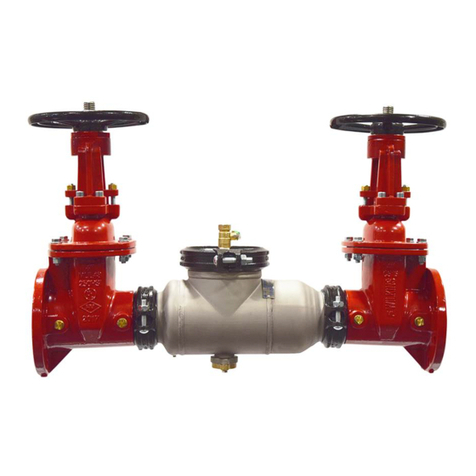
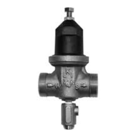
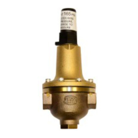
The Wilkins ZW109BP
Pressure Reducing Valve with Low Flow By-Pass
automatically reduces a higher inlet pressure to a steady lower downstream
pressure regardless of changing flow rate. The pressure reducing valve is
hydraulically operated and controlled by a BR4 pilot control, which senses
pressure at the main valve outlet. An increase in outlet pressure forces the
BR4 pilot control to close and a decrease in outlet pressure opens the control.
This causes the main valve cover pressure to vary, modulating the main valve
and thereby maintaining constant outlet pressure.
The control system is very
sensitive to slight pressure changes and immediately controls the main
valve to maintain the desired downstream pressure. Pressure setting
adjustment is made with a single adjusting screw
INSTALLATION
1. Allow sufficient room around the valve assembly to make adjustments
and for servicing.
2. lt is recommended that gate or line block valves be installed on both
ends of the ZW109BP valve assembly to facilitate isolating the valve for
maintenance. Minimum one pipe diameter apart.
NOTE: BEFORETHE VALVE IS INSTALLED, PIPE LINES SHOULD BE
FLUSHED OF ALL CHIPS, SCALE, AND FOREIGN MATTER.
3. Place the valve assembly in the line with flow through the valve in the
direction indicated on the inlet plate or by flow arrows. Check all fittings
and hardware for proper makeup and that no apparent damage is evident.
Be sure main valve cover nuts/bolts are tight.Pressure in some applications
can be very high so be thorough in checking and inspecting for proper
installation and makeup.
4.Wilkins Valves operate with maximum efficiency when mounted in hor-
izontal piping with the cover UP: however, other positions are acceptable.
Due to size and weight of cover and internal components of six inch and
larger valves, installation with the cover up is advisable.This makes periodic
inspection of internal parts readily.
OPERATION AND START-UP
1. Prior to pressurizing the valve assembly make sure the necessary
gauges to measure pressure in the system are installed as required by the
system engineer. An X101 Valve Position Indicator may be installed in the
center cover port to provide a visual indication of the valve movement dur-
ing startup.
CAUTION: During start-up and test procedures a large volume of water
may be discharged downstream. Check that the downstream venting is
adequate to prevent damage to personnel and equipment.All adjustments
in pressure should be made slowly while under flowing conditions. If
the main valve closes too fast it may cause surging in upstream piping.
2.If isolation valves (B) are installed in pilot system open these valves (see
ZW109BP schematic).
3.Optional CV Flow Controls (C or S) provide adjustable regulation of flow
in and out of the main valve chamber to minimize pulsations that some-
time occur at very low flow rates. If CV Controls are installed, loosen jam
nut and turn adjustment screw counterclockwise from closed position 3.5
turns for an initial setting.
4. Open the upstream gate or block valve just slightly to allow the main
valve assembly and pilot system to fill with liquid.
5. Carefully loosen tube fittings at highest points and bleed air from pilot
control system. Carefully loosen the plug at top of main valve cover to
bleed air from cover. If an indicator is installed, carefully loosen the air
bleed valve at top of indicator. Tighten tube fittings.
6. Open the upstream gate or block valve fully.
7.Slowly open the downstream gate or block valve.Flow should occur and
pressure should remain constant.
8. Adjust the Wilkins BR4 Controls to desired pressure.To change pressure
setting, turn the adjusting screw clockwise to increase pressure, counter-
clockwise to decrease pressure. There must be liquid flowing through the
valve during pressure adjustments. When the desired setting has been
made, tighten jam nut and replace cover. Low flow by-pass control (3A)
must be set higher than main BR4 (3B).
9. To check the operation of the valve, open and close the downstream
gate valve.The downstream pressure should remain constant.
10.If opening and closing speed controls (C or S) are installed in the valve
pilot system, fine tune the opening and closing speed of the main valve
while performing step 9.Turn the CV adjustment screw clockwise on the
opening speed control to make the main valve open slower. Turn the
adjustment screw clockwise on the closing speed control to make the main
valve close slower.When adjustments have been completed tighten
jam nuts.
MAINTENANCE
1. Wilkins Valves and Controls require no lubrication or packing and a
minimum of maintenance.However, a periodic inspection schedule should
be established. Minimum of once per year.
2. When ordering parts always refer to the catalog number and stock
number on the valve nameplate.
BR4 DISASSEMBLY
1. Note: distance that adjustment bolt protrudes from bell housing. Loosen
locknut on adjustment bolt, then turn adjustment bolt out of bell housing to
remove spring tension.
2. Unscrew bell housing counterclockwise and remove spring, spring disc
and friction ring.
3. Remove cartridge from BR4 by gripping retaining bolt with pliers and
pulling outwards away from body.
TO REASSEMBLE:
1. Replace old cartridge assembly with new cartridge assembly. Push the
cartridge into bore in body making sure o-ring seal tight against both the
cartridge and body.
2.Replace friction ring, spring, spring disc and bell housing.Make sure fric-
tion ring is installed with raised edge facing up. Tighten bell housing onto
body by threading clockwise.
3. Adjust BR4 to desired pressure by following stops 9 and 10 above.
4.Tighten locknut when desired pressure is achieved.
SYMPTOM PROBABLE CAUSE REMEDY
Main valve No pressure at valve inlet Check inlet pressure
fails to open Main valve diaphragm assembly Disassemble, clean and polish
inoperative stem, replace detective parts
Pilot Valve (BR4) not opening:
1. No spring compression 1.Tighten adjusting screw
2. Damaged spring 2. Disassemble and replace
Flow Control (CV) disc inoperative. Disassemble, clean and polish
corrosion or excessive scale stem. Replace worn parts
buildup on stem
Main valve Foreign matter between disc and Disassemble main valve, remove
fails to close seat or worn disc. Scale on stem matter, clean parts and replace
or Diaphragm ruptured defective parts
Flow Clean Strainer plugged Remove and clean or replace
CK2 (isolation valves) closed Open isolation valves
Pilot Valve (BR4) remains open:
1.Spring compressed solid 1. Back off adjusting screw
2.Mechanical obstruction 2. Disassemble and remove
obstruction
3.Worn seal ring 3. Disassemble remove and
replace cartridge assembly
Fails to Air in main valve cover and/or Loosen top cover plug and
regulate tubing fittings and bleed air
Pressure Reducing Valve with Low Flow By-Pass
ZW109BP
MODEL
