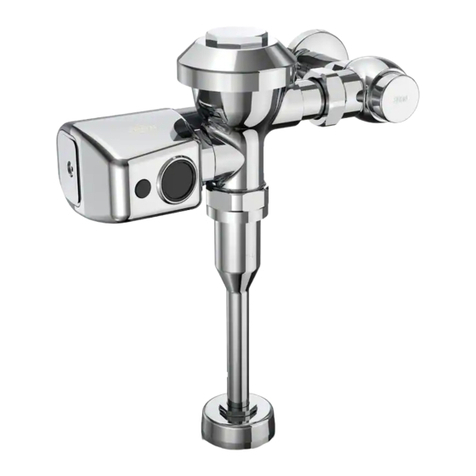
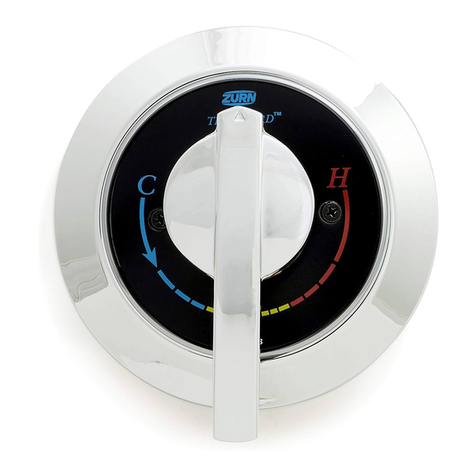
manuals.online logo
Brands
  1. Home
  2. •
  3. Brands
  4. •
  5. ZURN
  6. •
  7. Control Unit
  8. •
  9. ZURN AquaVantage ZH Series User manual

ZURN AquaVantage ZH Series User manual

Zurn Industries, LLC
511 W. Freshwater Way, Milwaukee, WI U.S.A. 53204 · Ph. 1-855-ONE-ZURN, Fax 919-775-3541
In Canada |Zurn Industries Limited
7900 Goreway Drive Unit 10, Brampton, Ontario L6T5W6 · Ph. 905-405-8272, Fax 905-405-1292
www.zurn.com
Rev. B
Date: 10/30/2018
C.N. No. SAN008373
Prod. | Dwg. No. FV241
ZH6152AV
ZH6003AV
AquaVantage®
ZH Series
Hydraulic-Operation Flush Valve
Installation, Operation, Maintenance
and Parts Manual
Patented and Patents Pending
LIMITED WARRANTY
All goods sold hereunder are warranted to be free from defects in material and factory workmanship for a period of three years from the
date of purchase. Decorative nishes warranted for one year. We will replace at no costs goods that prove defective provided we are
notied in writing of such defect and the goods are returned to us prepaid at Sanford, NC, with evidence that they have been properly
maintained and used in accordance with instructions. We shall not be responsible for any labor charges or any loss, injury or damages
whatsoever, including incidental or consequential damages. The sole and exclusive remedy shall be limited to the replacement of
the defective goods. Before installation and use, the purchaser shall determine the suitability of the product for his intended use
and the purchaser assume all risk and liability whatever in connection therewith. Where permitted by law, the implied warranty of
merchantability is expressly excluded. If the products sold hereunder are “consumer products,” the implied warranty of merchantability
is limited to a period of three years and shall be limited solely to the replacement of the defective goods. All weights stated in our
catalogs and listed are approximate and are not guaranteed.
WARNING: Cancer and Reproducve Harm - www.P65Warnings.ca.gov
ADVERTENCIA: Cáncer y daño reproducvo - www.P65Warnings.ca.gov
AVERTISSEMENT: Cancer et eets néfastes sur la reproducon - www.P65Warnings.ca.gov
Hydraulic-Operation
Closet/Urinal Systems
ZH6000AV
ZH6001AV
ZH6003AV
ZH6010AV
ZH6017AV
ZH6140AV
NOTE: The information in this manual is subject to change at any time without notice. Installations may
be performed at different times of construction by different individuals. For this reason, these instructions
should be left on-site with the facility or maintenance manager.
NOTICE: READ ENTIRE MANUAL PRIOR TO INSTALLING PRODUCT.
ZH6142AV
ZH6150AV
ZH6152AV
ZH6190AV
ZH6195AV
FV241 Rev. A 10/30/18 Page 2
PRODUCT SPECIFICATIONS: ZURN AquaVantage® ‘AV’ ZH Series
Exposed/Concealed Flush Valve – Exposed/concealed,quiet diaphragm-
type,chrome plated/rough brass, ushometer valve with Zurn’s AquaVantage
TPE, chloramine resistant, dual seal diaphragm with surface optimization and
clog resistant dynamic orice. The valve is complete with a non-hold-open type
feature with a hydraulic push-button actuator that may be located up to 36”
[914] (7’ [2133] with -SW option) from the valve, high back pressure vacuum
breaker, hex coupling nut,and adjustable tailpiece. Spud coupling and ange
for top spud connection for exposed valves. Elbow ush connection and
spud coupling for back spud connection for concealed valves. Control stop
has internal siphon-guard protection and sweat solder kit. Exposed valves
are supplied with vandal-resistant cap and a cast wall ange with setscrew.
Internal seals are made of chloramine resistant materials. Electrical box for
exposed valves supplied by others.
MODELS
Exposed
ZH6000AV – 1-1/2” Water closet valve with top spud connection.
ZH6001AV – 1-1/4” Urinal valve with top spud connection.
ZH6003AV – 3/4” Urinal valve with top spud connection.
ZH6010AV – 1-1/2” Water closet valve with back spud connection.
ZH6017AV – 1-1/2” Water closet valve with top spud connection.
Concealed
ZH6140AV – 1-1/2” Water closet valve with back spud connection.
ZH6142AV – 1-1/2” Water closet valve with top spud connection.
ZH6150AV – 1-1/2” Water closet valve for ushing rim oor drains.
ZH6152AV – 1-1/2” Water closet valve with back spud connection.
ZH6190AV – 1-1/4” Water closet valve with back spud connection.
ZH6195AV – 3/4” Urinal valve with back spud connection.
AquaVantage® Vavle Rough-In, Product Specication, Models, and Options
FLOW OPTIONS
Closets
-WS1 1.6 Gal. Low Consumption Flush
-FF 4.5 Gal. Full Flush
Standard Flush 3.5 Gal. Per Flush
Urinals
-WS1 1.0 Gal. Low Consumption Flush
-WS 1.5 Gal. Per Flush
Standard Flush 3.0 Gal. Per Flush
SUFFIX OPTIONS
Exposed
-MB 1” [25 mm] Metal Push Button Hydraulic Actuator
-SW Side Wall Mounted Hydraulic Actuator
-WP Wall Plate for Push Button (ZP-50)
-YJ Split Ring Pipe Support-YKSolid Ring Pipe Support
-YO Bumper on Angle Stop (Closets Only)
____ Other
Concealed
-FW Fixture Wall Mounting Hydraulic Actuator
-MB 1” [25 mm] Metal Push Button Hydraulic Actuator
-SW Side Wall Mounted Hydraulic Actuator
-WP Wall Plate for Push Button (ZP-50)
____ Other
ZH6000AV ZH6152AV
FV241 Rev. A 10/30/18 Page 3
Important:
• All plumbing is to be installed according to state and local
codes and regulations.
• Water supply lines need to allow proper water ow for each
xture.
• Flush all lines of any debris before making connections.
• Do not use pipe sealant or plumbing grease on any tting other
then the control stop inlet.
The AquaVantage valve is designed to operate under several
varieties of water pressure. The pressures fall between 10
and100 psi (69 to 689 kPa). Each valve is tested at the lowest
and highest pressures before being shipped.The minimum
pressure is determined by the type of xture purchased and
the gallons per ush requested. Consult your catalog for ow
options.Most low consumption valves (1.6 gallon) require a
minimum of 25 psi ow pressure. Rough-in for plumbing and
double gang box per specication sheet and Figure A. When
installing your quality Zurn valve it is recommended that to
protect the polished nishyou do not use a toothed wrench. This
will cause gouges and scratches on your valve.
STEP NO. 1
Measure distance from nished wall to centerline of xture spud;
cut supply pipe 1-1/4” shorter than this measurement. Chamfer
O.D. and I.D. (See Figure B.)
STEP NO. 2
Slide threaded adaptor onto supply pipe until shoulder stops on
endof pipe, then sweat-solder the adaptor to the water supply
pipe. (See Figure C.)
STEP NO. 3
Measure from nished wall to rst thread of adaptor for length
ofchrome tube. Cut chrome tube this length ‘X’. (See Figure C.)
STEP NO. 4
Slide wall escutcheon over chrome tube and slide both chrome
tubeand wall escutcheon over supply pipe pushing wall
escutcheonall the way to the wall. (See Figure D.)
STEP NO. 5
Screw control stop onto water supply adaptor. (See Figure E.)
Sweat Solder Adaptor Installation Instructions for Exposed Valves
FV241 Rev. A 10/30/18 Page 4
AquaVantage®Valve Installation Instructions for Exposed ZH Series
STEP 1
Control Stop Installation (Figure 1)
Install the Zurn control stop valve with “Siphon Guard” back check
protection (and wall escutcheon on exposed ushometer installations)
to the water supply line with outlet positioned as required.
Note: For sweat solder applications,see recommended instructions
on Page 3 or refer to those included in the Zurn sweat solder kit.
STEP 2
Install Vacuum Breaker Flush Connection (Figure 2)
Top Spud – Slide the tube nut, spud nut, ber washer, rubber gasket,
and xture escutcheon over the vacuum breaker tube and insert into
xture tube. Hand tighten spud nut into xture spud.
Back Spud – Assemble pipe,elbow,coupling nuts,ber washers,rub-
ber gaskets,and xture escutcheon as illustrated in Figure 2.
STEP 3
Installation of Main Valve Body
• Run the black inlet tube of the push button (Figure 4) through the
small hole of the cover plate (Figure 3).
• Run the clear outlet tube of the push button (Figure 4) through the
large bottom hole of the cover plate (Figure 3).
• Loosely mount the cover plate to the electrical box (Figure 3).
• Run the top black nylon tubing through the small cover tube and
small cover tube ring (Figure 3).
• Run the top clear bottom nylon tubing through the large cover tube
and large cover tube ring (Figure 3).
• Place the main valve body in position and connect the nylon tubing
to the compression ttings on the back of the ushometer (Figure
4).
• Tighten the compression ttings but do not over tighten.
• Position valve body on control stop body and vacuum breaker
tube. Valve body tailpiece compensates for mismatched rough-ins
on the job. Maximum adjustment is 1/2” [13 mm] plus or minus
the recommended 4-3/4” [121 mm] centerline of ush valve to
centerline of control stop dimension (Figure 5).
• Align ush valve with centerline of xture and tighten ush tube nut
and tailpiece nut.
• Push the cover tubes ush against the valve body and tighten the
setscrew on cover tube rings.
• Tighten the four screws on the wall plate using the hex wrench
(Figure 3).
• Push the cover tube rings against the cover plate and tightenthe
setscrews (Figure 3).
FV241 Rev. A 10/30/18 Page 5
STEP 4
Install push button actuator.
STEP 5
Flush out supply line (Figure 6). Make sure the control stop is closed.
Remove ushometer cover. Lift out the diaphragm kit assembly.
Install the ushometer cover, wrench tight and open stop. Turn on
water supply to ush line of any debris or sediment.
After completion, shut off control stop, remove cover and reinstallthe
diaphragm kit assembly. Install ushometer cover wrench tight.
STEP 6
Adjust Control Stop
Adjust the control stop to meet the ow rate required for proper
cleaning of the xture. Open control stop counterclockwise 1/2
turnfrom closed position. Activate ushometer with pushbutton.
Adjust the control stop after each ush until the rate of ow delivered
properly cleanses the xture. The nal setting for urinals should be
such that the xture will not overow when the valve is activated in
succession. The stop cap screw cover should be replaced after nal
adjustments have been made.
STEP 7
Install vandal-resistant cap with setscrews provided (Figure 7).
AquaVantage®Valve Installation Instructions for Exposed ZH Series
FV241 Rev. A 10/30/18 Page 6
Part Identication
AquaVantage®Repair Kits
1.Chrome Cover Plate
2. Return Cover Tube
3. Supply Cover Tube
4. Cover Tube Ring with Setscrew
5. Cover Tube Ring with Setscrew
6. Handle Nut
7. Hydraulic Plunger Assembly
8. 1/16” Compression Fitting
9. Gasket
10. Valve Body Cover
11. Plastic Cover
12. Trip Mechanism
13. Diaphragm Repair Kit
14. Valve Body
15. Vacuum Breaker Friction
Washer
16. Vacuum Breaker Insert
17. Vacuum Breaker Duckbill
18. Vacuum Breaker Tube
19. Vacuum Breaker Tube Nut
20. Spud Nut
21. Spud Friction Washer
22. Spud Sleeve
23. Spud Escutcheon
24. Tailpiece
25. Snap Ring
26. Tailpiece O-Ring
27. Locking Nut
28. Setscrew for Cast Wall Flange
29. Cast Wall Escutcheon
30. Supply Cover Tube
31. Sweat Solder Adaptor
32. Stop Body
33. Piston Seal
34. Piston
35. Stop Spring
36. Guide O-Ring
37. Piston Guide
38. Guide Holder
39. Adjusting Screw
40. Stop Cap
41. Snap Cap Screw Cover
42. Vandal-Resistant Control Stop
Cover
43. Setscrew for Control Stop Cover
44. 1/4” Return Tube
45. 1/4” Supply Tube
46. 1/8” Compression Fitting
47. Piston Assembly
48. Actuator Body
49. Mounting Plate
50. Securing Nut
51. Spring for Large Push Button
52. Spacer for Large Push Button
53. Large Push Button
54. Escutcheon Setscrew
55. Escutcheon for Large Push
Button
56. Filter
Covers and Repair Kits Product No.
Outside Cover - CP – Item 10 P6000-LL
Inside Cover – Item 11 P6000-L
Low Consumption Closet Kit – 1.6 gal. ush P6000-ECA-WS1
Water Saving Closet Kit – 3.5 gal. ush P6000-ECA-WS
Full Flow Closet Kit – 4.5 gal. ush P6000-ECA-FF
Low Consumption Urinal Kit – 1.0 gal. ush P6000-EUA-WS1
Water Saving Urinal Kit – 1.5 gal. ush P6000-EUA-WS
Full Flush Urinal Kit – 3.0 gal. ush P6000-EUA-FF
Repair Parts – Inside Parts Product No.
Urinal Relief Valve – Item 12 P6000-EU13
Closet Relief Valve – Item 12 P6000-EC13
AquaVantage Rebuild Kits Product No.
Closet and Urinal Rebuild Kits Include:
Items 4-9, 12, 13, 15-17, 26
P6000-ECA-WS-RK
P6000-ECA-WS1-RK
P6000-EUA-WS-RK
P6000-EUA-WS1-RK
Actuator Assembly and Repair Kits Product No.
Hydraulic Large Push Button Assembly,
Fixture Wall
PH6000-HYL3-
FW
Hydraulic Large Push Button Assembly, Side
Wall
PH6000-SHYL3-
SW
Hydraulic Metal Push Button Assembly PH6000-HYL-MB
Hydraulic Metal Push Button Assembly for Penal
Use
PH6000-HYLP-MBP
Repair Kit for Hydraulic Actuator PH6000-HYA11
Control Stop Repair Kit and Parts Product No.
Control Stop Repair Kit for 1" and 3⁄4", P6000-D-SD
Includes Items 33-39
Seal Seat for 1" and 3⁄4", Includes Item 33 P6000-D42
VP Control Stop Repair Kit for 1" and 3⁄4", P6000-D-VP
Includes Items 33-39
Sweat Solder Connection with Cast Wall Flange, P6000-YB
Includes Items 29-31
Adjustable Tailpieces Product No.
Adjustable Tailpiece for Standard Flush Valve, P6000-J1
Includes Items 24-26
Tailpiece Coupling Assembly, Includes Items 25-27 P6000-K
Tailpiece Locking Ring, Includes Item 25 P6000-C30
Tailpiece O-Ring, Includes Item 26 P6000-C31
Coupling Nut, Includes Item 27 P6000-C32
Flush Connections and Spud Coupling Kits
Product No.
Flush Tube Assembly for Flush Valves, Includes P6000-A
Items 15-19. Specify diameter and length.
Vacuum Breaker Repair Kit, Includes Items 15-17 P6000-B
Spud Coupling Assembly, Includes Items 20-23. P6000-H
Specify size.
FV241 Rev. A 10/30/18 Page 7
Care of Chrome Plated Surfaces
The suggested cleaning of chrome-plated surfaces is to simply wash with mild soap and water, then dry. Commercial cleaning
compounds are never recommended as they may dull the luster and the decorative nishes.
AquaVantage®Trouble Shooting Guide
Problem Cause* Corrective Action*
Valve will not operate. 1. Water supply is shut off.
2. Internal valve lter is plugged.
3. Tubing is hooked up improperly.
4. Plunger orice is clogged.
5. Damaged or worn seals in HYM Actuator.
1. Turn on water supply/stop valve.
2. Clean or replace lter.
3. Refer to instructions for proper connections.
4. Remove plunger and clear orice.
5. Replace HYM Actuator.
Insufcient volume of
water to adequately
evacuate xture.
1. Stop valve is not open enough.
2. Urinal trip mechanism installed in closet valve.
3. Inadequate supply running pressure.
4. Diaphragm kit is not matched to the xture.
1. Open stop valve until desired ush.
2. Replace black urinal trip mechanism with a whit
closet trip mechanism.
3. To determine if the supply is adequate to evacuate
the xture, remove all working parts except for the
diaphragm, then open the stop valve and evaluate
ush.
4. Replace diaphragm kit with proper assembly.
Flush valve shuts off too
quick or is short ushing.
1. Damaged or punctured diaphragm.
2. Enlarged orice.
1. Replace diaphragm to remedy problem.
2. Replace diaphragm to remedy problem.
Flush valve will not shut
off.
1. Trip mechanism is not seating properly.
2. By-pass orice is plugged or partially plugged.
1. Disassemble parts and clean thoroughly.
2. Examine by-pass orice and clean if necessary,
being careful not to enlarge orice opening.
Continuous trickle of
water through valve.
1. Tubing is hooked up improperly.
2. Debris lodged between piston assembly and valve
seat.
1. Refer to instructions for proper connections.
2. Remove the piston from the push button assembly
and inspect and clean both the spool and the valve
seat.
Actuator assembly
leaking.
1. Actuator assembly handle nut is loose.
2. Actuator assembly gasket(s) are missing.
1. Tighten the actuator assembly nut.
2. Install gasket(s).
Push button assembly
leaking.
1. Compression tting or nuts are loose.
2. Piston O-Ring is damaged.
1. Tighten nuts or ttings.
2. Replace piston assembly.
Seasonal Use
Valves used in installations subject to shutdown during cold and/or freezing conditions should be maintained in the following manner:
After the main supply has been shut off and the water has been drained from the system, remove the stop cap and the stop valve
internals to allow the water to drain from the ush valve itself. The tubing must also be disconnected from the push button assembly
and the actuator assembly to allow for drainage.
FV241 Rev. A 10/30/18 Page 8
ZURN INDUSTRIES, LLC COMMERCIAL BRASS OPERATION, 5900 ELWIN BUCHANAN DRIVE, SANFORD, NC, U.S.A. 27330
PHONE: 1-800-997-3876 FAX: 919/775-3541 www.zurn.com
ZURN INDUSTRIES LIMITED 3544 NASHUA DRIVE, MISSISSAUGA, ONTARIO L4V 1L2 PHONE: 905/405-8272 FAX: 905/405-1292

This manual suits for next models

11

Other ZURN Control Unit manuals

ZURN AQUA-GARD ZW1070/15 Maintenance and service guide

ZURN

ZURN AQUA-GARD ZW1070/15 Maintenance and service guide

ZURN AquaSense ZTR Series User manual

ZURN

ZURN AquaSense ZTR Series User manual

ZURN ZW215FP Installation manual

ZURN

ZURN ZW215FP Installation manual
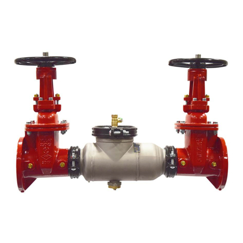
ZURN TEMP-GARD Z7100 User manual

ZURN

ZURN TEMP-GARD Z7100 User manual

ZURN WILKINS 950LF User manual

ZURN

ZURN WILKINS 950LF User manual

ZURN ZER6000AV-CPM User manual

ZURN

ZURN ZER6000AV-CPM User manual

ZURN 350AST Series User manual

ZURN

ZURN 350AST Series User manual
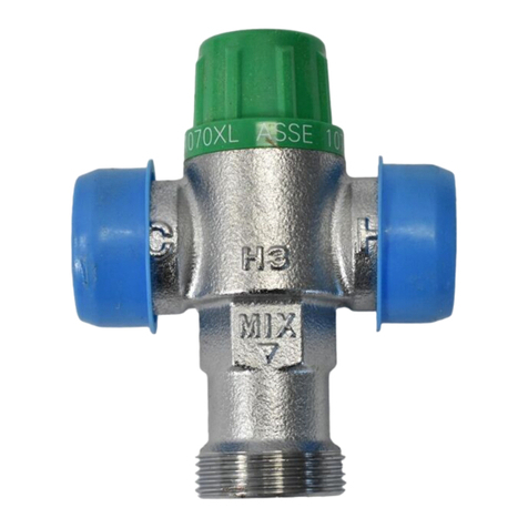
ZURN LEAD-FREE ZW209 Manual

ZURN

ZURN LEAD-FREE ZW209 Manual

ZURN 350 User manual

ZURN

ZURN 350 User manual

ZURN Aquaflush Z6001 User manual

ZURN

ZURN Aquaflush Z6001 User manual

ZURN WILKINS 450 User manual

ZURN

ZURN WILKINS 450 User manual

ZURN AquaSense ZER-SM Series User manual

ZURN

ZURN AquaSense ZER-SM Series User manual

ZURN TEMP-GARD III Z7300-SS-MT-HW-H9 User manual

ZURN

ZURN TEMP-GARD III Z7300-SS-MT-HW-H9 User manual

ZURN AquaSense ZER-W2 Series User manual

ZURN

ZURN AquaSense ZER-W2 Series User manual

ZURN Wilkins ZW109BP Owner's manual

ZURN

ZURN Wilkins ZW109BP Owner's manual

ZURN Metroflush Z6200 series User manual

ZURN

ZURN Metroflush Z6200 series User manual

ZURN AquaSense ZER-SM Series User manual

ZURN

ZURN AquaSense ZER-SM Series User manual

ZURN WILKANS PV-PRD User manual

ZURN

ZURN WILKANS PV-PRD User manual
ZURN WILKINS BR4EC User manual

ZURN

ZURN WILKINS BR4EC User manual

ZURN QHCMKIT5 User manual

ZURN

ZURN QHCMKIT5 User manual
ZURN WILKINS ZW109FP Owner's manual

ZURN

ZURN WILKINS ZW109FP Owner's manual
Popular Control Unit manuals by other brands

Dräger Plus Series Instructions for use

Dräger

Dräger Plus Series Instructions for use

Bucher Hydraulics NS 32 quick start guide

Bucher Hydraulics

Bucher Hydraulics NS 32 quick start guide

Goetze 651 mHNK Assembly and maintenance instructions

Goetze

Goetze 651 mHNK Assembly and maintenance instructions

Marsupial Eurorack Assembly instructions

Marsupial

Marsupial Eurorack Assembly instructions

Murata LBUA5QJ2AB user manual

Murata

Murata LBUA5QJ2AB user manual

IFM Electronic efector 600 TR2432 operating instructions

IFM Electronic

IFM Electronic efector 600 TR2432 operating instructions

Omron SYSMAC C500-NC222-E Operation manual

Omron

Omron SYSMAC C500-NC222-E Operation manual

E-Plex 413DWM instructions

E-Plex

E-Plex 413DWM instructions

Burkert 2610 operating instructions

Burkert

Burkert 2610 operating instructions

Siemens Simatic S7-1500 Equipment manual

Siemens

Siemens Simatic S7-1500 Equipment manual

CHIEF AVM1 installation instructions

CHIEF

CHIEF AVM1 installation instructions

PSG Wilden XSD HS Series Engineering, operation & maintenance

PSG

PSG Wilden XSD HS Series Engineering, operation & maintenance

Lucent Technologies Stinger STGR-LIM-AD-48 Guide

Lucent Technologies

Lucent Technologies Stinger STGR-LIM-AD-48 Guide

YOKOGAWA XS110A user manual

YOKOGAWA

YOKOGAWA XS110A user manual

National Instruments NI 9472 operating instructions

National Instruments

National Instruments NI 9472 operating instructions

Gemtek WMIA-166AG user guide

Gemtek

Gemtek WMIA-166AG user guide

Moog G761 Series Installation and operation instruction

Moog

Moog G761 Series Installation and operation instruction

Pond Technics Pro Tech 700505 manual

Pond Technics

Pond Technics Pro Tech 700505 manual

manuals.online logo
manuals.online logoBrands
  • About & Mission
  • Contact us
  • Privacy Policy
  • Terms and Conditions

Copyright 2025 Manuals.Online. All Rights Reserved.