21st Century Alarms LuxHome LCD User manual

LuxHome LCD
Wireless Alarm
System User Guide
About Your Alarm System 01
01. Full Arm 01
02. Part Arm 1 01
03. Part Arm 2 02
04. Disarm 02
05. Quick Set 02
06. Omit Zone 02
07. Panic Alarm 03
08. Event Log 03
09. Chime 03
10. Event Log 03
11. Voice Dialer 04
12. Latch Key 04
13. Remote System Control 04 + 05
14. Testing the Alarm System 06 + 07
15. Removing Detectors for
Decorating 08
16. Battery Monitoring 09
17. Wire Free Siren 09
18. Low Battery Indication 09 + 10
19. 10Maintenance
20. 11Alarm Record
21. Trouble Shooting 12 + 13
Contents Page
LuxHome LCD Wireless Alarm
When leaving the premises, the system must be Armed. However, before doing so, check that all
windows are closed and locked, all protected doors are closed and PIR Detectors are not obstructed.
Ensure that pets are restricted to areas not protected by PIR Detectors.
The system has three arming modes, ARM, Part-Arm 1 and Part-Arm 2. The Part-Arm modes allow
for selected zones to be left in a Disarmed state while the reminder of the system is Armed.
When the system is Armed (in any mode) the Control Panel will display the arming mode and the
status of the Latch Key for a few seconds. If enabled, the system Exit-Delay will start and be
counted down on the display. As the Exit-Delay expires the Control Panel will beep, with the beep
rate increasing in steps as the delay expires. At the end of the Exit-Delay all active zones be Armed.
By this time the user must have left the property and closed the final exit door.
If while the system is armed a detector on an active zone is triggered, if enabled, the programmed
Entry-delay for that zone will start and be counted down on the display. As the Entry-Delay expires
the Control Panel will beep, with the beep rate increasing in steps as the delay expires. If the system
has not been disarmed when the Entry-Delay expires an alarm will occur. If however, the Entry-Delay
for the triggered zone has been disabled an alarm will occur immediately.
At the end of the programmed alarm duration the Siren and Control Panel alarms will stop and the
system will automatically re-Arm.
01 - Full Arm
The system can be set in ARM mode using either the Remote Control or the Control Panel as
follows:
Remote Control: Press the ‘ARM’ button .
Control Panel: Press the Arm button followed by the User Password and then the Enter button:
, ? ? ? ? ,
User Access Code
By pressing button, the programmed exit delay will be overrided to 5 seconds.
02 - Part-Arm 1
The system can be set in PART-Arm 1 mode using either the Remote Control or the Control Panel
as follows:
Remote Control: Press the ‘PART-ARM’ button .
Control Panel:
, ? ? ? ? ,
User Access Code
By pressing button, the programmed exit delay will be overrided to 5 seconds.
Page 01

03 - Part-Arm 2
The system can be set in Part-Arm 2 mode using either the Remote Control or the Control Panel
as follows:
Remote Control: Press the ‘PART-ARM’ button twice: , .
Control Panel: , ? ? ? ? ,
User Access
, ? ? ? ? ,
Access Code
By pressing button, the programmed exit delay will be overrided to 5 seconds.
04 - Disarm
The system can be Disarmed using either the Remote Control or the Control Panel as follows:
Remote Control: Press the ‘DISARM’ button .
Control Panel: , ? ? ? ? ,
User Access
Code
If the system is disarmed and the ‘ALARM MEM’ LED is flashing with the panel beeping every few
seconds, this indicates that an alarm condition has occurred. Use the Event Log to find out and make
a note of where the alarm occurred to assist in tracing the cause of the alarm.
05 - Quick Set
To operate the quick set function and fully arm the system in 5s, overriding the programmed exit
delay.
Press
, ? ? ? ? ,
User Access
Code
06 - Omit Zone
To omit a zone from the next armed session:
1. Press
, ? ? ? ? ,
User Access
Code
2. Scroll through the menu until the required zone is displayed. The current setting will also be
displayed.
3. To change the setting press
, ,
,
.
4. Press to omit the zone, (i.e. zone omit ON). Press to re-enable the zone, (i.e. zone
omit OFF).
After configuring zones to be omitted as required, press ESC! to return to Standby mode.
Note: Omitting a zone will only affect the next armed session. When the system is disarmed the
omitted zones will be re-enabled ready for the next armed session.
Page 02 07 - Panic Alarm
A full Alarm condition can be immediately initiated at any time (whether the system is Armed or
Disarmed) in the event of threat or danger by activating a Panic switch on either the Remote Control
or the Control Panel.
Remote Control: Slide the Panic switch upwards.
Control Panel: Press and hold the button for approximately 3 seconds.
The alarm will continue either for the alarm duration when the system will automatically reset or until
the system is disarmed.
08 - Tamper
If the battery cover of any device is removed or if the Siren or Control Panel are removed from the
wall then a Full Alarm condition will be initiated even if the system is Disarmed. The alarm condition
will continue either for the alarm duration when the system will automatically reset or until the system
is Disarmed. The ‘ALARM MEM’ LED on the Control Panel will flash and the panel will beep every
few seconds to indicate an alarm has occurred.
Note: The Tamper protection facility on the Siren operates independently. If the Tamper on the Siren
is activated this will not be indicated at the Control Panel.
09 - Chime
The Chime facility can only be operated with the system in Standby mode.
Press to toggle the Chime facility between ON and OFF.
Note: If the Chime is ON and the system is then armed the Chime will remain ON after the system
is disarmed.
10 - Event Log
The Event Log will store the last 50 system Arm, disarm, alarm and detector Low Battery events.
The Event Log will record the time, date and details for each event. If when the system is disarmed
the “ALARM MEM’ LED is flashing and the panel beeps every 10s, this indicates that an alarm has
occurred. To cancel the LED and stop the beeping you must access the event log or press ESC! to
eliminate the flashing ‘ALARM MEM’ LED and the beeping as well.
1. To access the Event Log, (with the system in Standby), press .
The Event-Log will automatically start scrolling through and displaying the event data starting
with the most recent event. The data for each event is shown on two screens, each screen will be
displayed for 5 seconds before moving on to the next screen and then the next event.
2. Use the and buttons to manually scroll through the event log to the required position
as necessary.
3. Press ESC! to return to standby.
Page 03

11 - Voice Dialer
13 - Remote System Control
If the Remote System Control facility is enabled, the Control Panel will answer the call after the set
number of rings and emit three beeps on the phone line to prompt for a User Password to be entered
using the telephone keypad.
A valid User Password will be acknowledged with one long beep. An incorrect code will be
acknowledged by two short beeps. If the User Password is not entered within 30s or is entered
incorrectly three times then the Control Panel will automatically hang-up the line.
Note: If the internal Answer-Phone is also enabled and there is space for a new message then
the call will be answered with the Answer-Phone greeting message. The User Password should
be entered during the greeting message, otherwise the answer phone message recorder will be
activated.
If the Voice Dialer is enabled and an alarm condition occurs, the system will call for help using your
recorded alarm messages and up to four telephone numbers.
When an alarm condition occurs, the telephone voice dialer (if enabled) will call the first enabled
number in the calling sequence and replay the recorded alarm messages for the configured ‘Play
Time’. The recipient must acknowledge the message by pressing the button on their telephone
keypad. If the call is unanswered or an acknowledgment is not received then the next active number
in the dialing sequence will be called. The dialer will continue calling each number in turn until either
all numbers in the sequence have been dialed the set number of times or the sequence is cancelled/
acknowledged by the recipient.
12 - Latch Key
When the system is disarmed the Latch-Key facility, if enabled, will call the first latchkey phone
number and replay the user message (recorded under user setup) for the set ‘Play Time’. The
recipient must acknowledge the message by pressing the button on the telephone keypad. If the
call is unanswered or an acknowledgment is not received then the second latchkey phone number
will be called. The voice dialer will continue calling each number in turn until each number has been
dialed the set number of times or the sequence is cancelled/acknowledged by the recipient.
By pressing the # button on the telephone keypad within 30 seconds, the Control Panel will
automatically hang-up the line.
Use with an External Answer-Phone:
If the Remote System Control is to be used in conjunction with an external Answer-Phone then:
1. The internal Answer-Phone must be disabled.
2. The number of ‘ring to answer’ for the Control Panel must be greater than that of the External
Answer-Phone, otherwise the Control Panel will always pickup the call before the Answer-
Phone.
Page 04 Page 05
To access the Remote System Control facility the Control Panel has a ‘double dial-in’ feature to
enable the Control Panel to pick-up the phone call before the external Answer-Phone cuts in. T h e
‘double dial-in’ procedure is as follows:
1. Dial up the system and hang up after two rings.
2. Redial up the system within 24s as maximum (12s as minimum), the system will pickup the phone
after 1 ring.
3. Enter the User Password as normal.
The following functions may be accessed via the remote. The system will acknowledge each signal
with a single long beep.
Press 1 to initiate ARM.
Press 2 to initiate Part-Arm 1.
Press 3 to initiate Part-Arm 2.
Press 4 to Disarm the system.
Press 5 to turn the Siren OFF.
Press 6 to turn the Siren ON.
Press 7 to Listen-In via the Control Panel Microphone.
Press # to stop Listen-In.
Note: Listen-in will be automatically cancelled after 5 minutes if not cancelled manually.
Press
8
to interrogate the system status. The status tone will be repeated at 2s intervals for 15s:
One beep: ARM
Two beeps: Part-Arm (1 or 2)
Three beeps: Alarm triggered
Four beeps: Fire triggered
One long beep: Disarmed
Press 9 to replay Answer-Phone messages.
While replaying a message, press # for 2 seconds to skip to the end of the message and hear
the next message.
Press 0 to delete all Answer Phone messages.
Press # to end the session and hang up the Control Panel line.
13 - Remote System Control

Page 06 Page 07
14 - Testing The Alarm System
The Control Panel has a programmed test routine. You may test the system at any time, however it
is recommended that the system is tested at regular intervals not exceeding 3 months.
With the system in Standby Mode
Press
User Password
. This puts the system into Test Mode.
The Arm and Part-Arm LEDs will flash.
The system is now in the Test Mode.
Use the and buttons to scroll through the menu and press
, ,
,
to select the displayed
test function or sub-menu.
Note: After completing all required test functions, press ESC! to leave Test mode and return to
Standby.
Walk Test
Before commencing testing, please ensure that there is no movement in any PIR protected area, all
doors/windows protected by Magnetic Contact Detectors are closed and that all battery covers and
housings are correctly fitted.
Scroll through the top level Test Mode menu until ‘Walk Test’ is displayed and press
, ,
,
.
‘Walk Test Waiting…’ will be displayed.
1. Trigger each detector on the system by either walking into a PIR protected area or by opening a
door/window protected by a Magnetic Contact detector. As each detector is triggered the Control
Panel will chime to indicate that an alarm signal has been received and the identity of the zone
that the detector is configured for will be displayed.
2. Operate detector anti-tamper switches by opening the case of the device. As the switches are
operated the Control Panel will chime and ‘Accessory Tamper’ will be displayed.
3. Activate each button on the Remote Control in turn. As each button is pressed the Control Panel
will chime and the button name will be displayed. (e.g. ‘REMOTE CONTROL DISARM’).
Press ESC! to exit Walk Test and return to the top level Test Mode menu.
Alarm Test
Scroll through the top level Test Mode menu until ‘Alarm Test’ is displayed and press
, , , .
Scroll though the menu until the required alarm displayed and press
, , , to operate the selected
alarm for 5 seconds.
Select ‘Wirefree Siren Test’ to operate the External Solar Siren.
Select ‘Hardwired Siren Test’ to operate the Control Panel Siren and external hardwired Siren (if
connected).
Select ‘Relay Test’ to operate the External hardwired (N.O./N.C.) relay contacts (if connected).
Press ESC! to exit Alarm Test and return to the top level Test Mode menu.
Wirefree Siren Service On/Off
Scroll through the top level Test Mode menu until ‘Wirefree Siren Service ON/OFF’ is displayed
and press
,
.
This offers the flexibility of removing or changing siren’s battery. Wait for 10 seconds until ON/OFF
duration has elapsed, then go ahead with fixing the siren as desired.
Voice Dialer Test
Scroll through the top level Test Mode menu until ‘VOICE DIALER TEST’ is displayed and press
,
.
In order to test the voice dialer properly, the prerequisite is to set the telephone number, record the
message and enable the call routing in the programming mode.
When testing is in progress, simply press ESC! to stop testing.
If ‘Line Status’ LED is flashing, it implies bad telephone line connection or telephone network being
out of order. Check the telephone line and re-test it.
Digital Dialer Test
Scroll through the top level Test Mode menu until ‘Digital Dialer Test’ is displayed and press
, ,
,
.
In order to test the digital dialer properly, the prerequisite is to set the telephone number and unit ID
number in the programming mode.
When testing is in progress, simply press ESC! to stop testing.
If ‘Line Status’ LED is flashing, it implies two causes of failure. One is bad telephone line connection
or telephone network being out of order. The other cause of failure is derived from the central
monitoring station. Consult with the central monitoring station for help.
14 - Testing The Alarm System

Page 08 Page 09
15 - Removing Detectors for Decorating
The LuxHome LCD Wireless Alarm System is Fully Tampered and will activate the Alarm if
tampered with, if you wish to remove a Detector or the Control Panel for Decorating the Alarm
System will need to be placed in “Test Mode” to disable “Tamper”
Method
Passive Infra-Red (PIR)
1. To disable “Tamper” you will need to put the system in “Test Mode”
2. With the system in Standby Mode with the Power LED ON, press:
The system is now in the Test Mode with Tamper disabled
3. Removing a PIR, carefully undo the screw at the bottom of the PIR and put somewhere safe,
....remove the cover, the PIR will be mounted by 1 or 2 screws, unscrew and remove the base.
4. To Replace the PIR base, find to original wall plug(s) and replace the screw(s), making sure
....not to over tighten as this may cause the PIR Housing to warp.
5. Replace PIR cover making sure to align the top of both the PIR and Base, and clip together,
....this must be tight connection, if misaligned or not tight "Tamper" will remain open.
6. Replace the bottom screw at the bottom of the PIR.
7. When finished:
ESC! to leave Test mode and return to
Standby.
Press
Door/Window Contact
It you need to remove a Door or Window Contact, follow Steps 1 and 2 as above.
The Contact Transmitter (long part with Battery) will be Super Glued in Place, to remove you will
need a Razor Blade or Stanley Knife.
Carefully insert the Blade under the Contact and pry free and put somewhere safe.
The Contact (small white magnet) will be held in place by a Sticky pad or Super Glue, follow the
same method as for The Contact Transmitter, and keep with the Contact Transmitter and Contact
together.
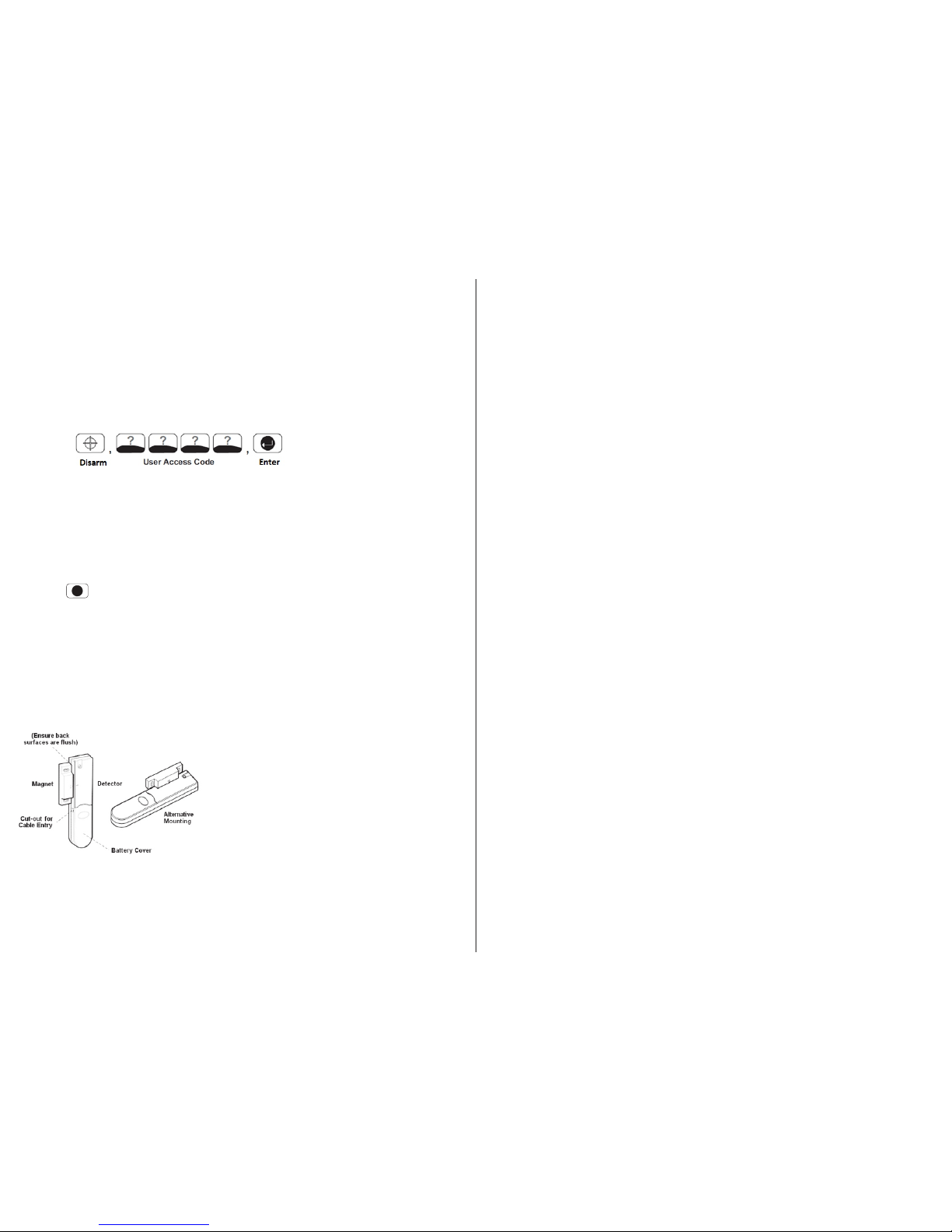
When Replacing the Door/Window Contact, fit the magnet
on the Moving Part of the Door and Transmitter on to the
frame, use Super Glue or Sticky Pads, the gap between
the magnet and Transmitter must be no more than 10mm
and the arrow on the Magnet is aligned with the (-) mark
on the Transmitter, the front cover on the Contact needs to
be aligned and closed tight to avoid “Tamper” activations,
follow step 7 as above to leave Test mode and return to
Standby.
It is not recommended that the Control Panel, or Bell Box be removed by the user as these items
st
contain High Voltage, please contact 21 Century Alarms for further information.
16 - Battery Monitoring
PIR and Magnetic Detectors continuously monitor their battery condition. The Control Panel also
monitors the battery condition of all PIR and Magnetic Detectors. If the battery level of any device
drops below acceptable levels then its low battery indication will be activated. In addition if any PIR
or Magnetic Contact detector has a low battery status it will be recorded by the Control Panel and a
message stored in the event log.
17 - Wire Free Siren
Your Siren & Strobe requires very little maintenance. However, a few simple tasks will ensure its
continued reliability and operation.
1 At least once a year, preferably in the autumn, the solar panel on the top of the siren housing
should be cleaned using a soft, damp cloth. This operation will ensure that the solar panel
receives all of the available light.
2 The Siren & Strobe incorporates tamper protection for system security. Should you, for any
reason, have to completely power down the Siren & Strobe (e.g. to move the system to new
premises). You will need to put the Solar Siren into ‘Service Mode’ as described above.
WARNING - The Siren Will Sound
Disconnect the siren rechargeable battery and initial power-up battery.
3 The Siren & Strobe should not be left for long periods with the batteries connected, unless the unit
is able to receive sufficient light to maintain the battery charging circuit. Failure to maintain charge
to the unit will result in the rechargeable battery running unacceptably low. Should this occur, the
unit must be recharged from a mains adaptor. When re-powering the Siren & Strobe fit a new 9V
PP3 leak proof alkaline initial power-up battery to ensure that the system receives sufficient power
until the solar panel can recharge the main battery completely.
4 The main rechargeable battery has a typical life of 4 years and needs no maintenance during
this period, providing the battery is kept charged. The battery will be damaged if it is stored in a
discharged state.
18 - Low Battery Indication
Note: Before removing the battery cover on any device to replace the battery ensure that the system
is put into Test mode to avoid initiating a Full Alarm condition.
The low battery indication for each system component is as follows:
Control Panel:
During a period of mains supply interruption the Control Panel will be powered by the rechargeable
backup batteries. Under normal battery conditions the Power LED on the panel will flash at 1s
intervals. However, under low battery conditions the Power LED will flash at 3s intervals.
Remote Control:
When the Remote Control is operated under low battery conditions the transmit LED will continue
to flash after the button has been released. Under normal battery conditions the LED will
extinguish when the button is released.
PIR Detectors:
Under low battery conditions the LED behind the detector lens will flash when movement is
detected to indicate that the battery needs to be replaced. Under normal battery conditions the
LED does not illuminate unless the PIR detector is in Walk Test mode.

Page 10 Page 11
Magnetic Contact Detectors:
Under low battery conditions, when the Detector is activated the transmit LED will be illuminated
for approximately 1s as the door/window is opened.
Under normal battery conditions the LED will not illuminate as the Detector is operated, (unless
the Detector is in Test Mode with the battery cover removed).
19 - Maintenance
Your Alarm System requires very little maintenance. However, a few simple tasks will ensure its
continued reliability and operation.
Control Panel
The rechargeable batteries have a typical life of 3-4 years and need no maintenance during this
period, provided they are kept charged. The batteries will be damaged if they are stored in a
discharged state for long periods.
Detectors And Remote Control
The Detectors require very little maintenance. The batteries should be replaced once a year or when
a low battery status is indicated.
Important: Should you, for any reason, have to completely power-down the system (e.g. to move
the system to a new premises) first put the system into Test mode before removing the Control Panel
cover and disconnecting the power supply and backup batteries.
Batteries
Before removing the battery cover on any device to replace the battery, ensure that the system is put
into Test mode to avoid initiating an Alarm.
The specifications for replacement batteries are as follows:
Remote Controls 1 x 3V CR2032 Lithium Cells
(or equivalent)
Magnetic Contact Detectors 2 x 3V CR2032 Lithium Cells
(or equivalent)
PIR Detectors 1 x 9V PP3 Alkaline
Note: Where applicable only fit PP3 Alkaline type batteries. Rechargeable batteries should NOT
be fitted.
At the end of their useful life the batteries should be disposed of via a suitable Recycling Centre. Do
not dispose of with your normal household waste. DO NOT BURN.
The Rechargeable batteries contain Sulphuric Acid – DO NOT ATTEMPT TO OPEN THE CASING.
18 - Low Battery Indication 20 - Alarm Record
Complete the following information during installation for future reference when adding to your
system and to assist Trouble Shooting.
Zone Settings
Zone
Detector
Type(s)
Location
Type
Final
Exit
Entry
Delay
Chime
Arm
Part-Arm
1
Part-Arm
2
1
2
3
4
5
6
7
8
9
10
You may make
a note of
your User Password and Installer Password below.
System Password
User 1:
_ User 2:
_ User 3:
_
User 4:
_ User 5:
_ User 6:
_
Master User: _
_
System House Code
Use the diagram
to record your House Code
ON ECE
1 2
3
4 5 6 7 8
Voice Dialer Phone Numbers
Phone No. 1:
_ Phone No. 2:
_
Phone No. 3:
_ Phone No. 4:
_
Latch-Key Phone Numbers
Phone No. 1:
_ Phone No. 2: _ _
Digital Dialer Phone Numbers
Phone No. _ _ _ System ID No. _
This information is confidential and should be kept in a safe location.

Page 12
21 - Trouble Shooting
Control Unit not working – Power LED OFF or
flashing
1.
Mains power failure – check if
other electrical
circuits
are operable.
2.
Check that mains adaptor is plugged in
and
socket is
switched
ON.
3.
Check mains fuse in Plug has not blown.
4.
Check that DC jack
plug from
mains adaptor is
connected in Control Panel.
5.
Check fuse/MCB in Consumer Unit on the
circuit serving the Control Panel.
Note: Before replacing any fuses or resetting
the MCB, the cause of
the failure should be
investigated and rectified.
Answer-Phone not responding or recording
messages
1.
Telephone line
not connected or faulty
– check
phone line with another phone
2.
Dial Method incorrectly
programmed
3.
Answer-Phone
disabled
4.
No space in message store,
6 messages
already recorded.
Cannot record Voice-Memo message at Control
Panel
1.
No space in message store, 6 messages
already recorded.
Control Unit not accepting User Password
1.
Pause between
key depressions too long.
Do
not pause for more than 5 seconds between
pressing keys.
2.
Incorrect code entered.
3.
Reset to factory defaults and reprogram
system.
Control Unit not responding to detectors
1.
Ensure that the ‘House Code’ is correctly
set.
2.
Ensure detector is within effective radio range
of Control Panel and equipment is not mounted
close to metal objects.
3.
Detector battery low – replace battery.
Voice-Dialer not responding to Alarm
1.
Telephone
line
not connected or faulty
– check
phone line with another phone
2.
Dial Method incorrectly
programmed
3.
Incorrect phone numbers programmed
4.
Phone numbers disabled in dialing sequence
5.
Alarm messages not recorded
Control Unit not contacting central monitoring
station service
on alarm
1.
Telephone
line
not connected or faulty
– check
phone
line with another phone.
2.
Dial Method incorrectly programmed.
3.
Incorrect phone number for central monitoring
station service programmed
4.
Incorrect system ID number for
central
monitoring station service programmed.
5.
Central monitoring
station service not
commissioned or signed up.
Control Unit not responding to Remote Phone
Access
1.
Telephone
line
not connected or faulty
– check
phone
line with another phone
2.
Remote Access disabled
3.
Incorrect User Password
entered
Latch Key not responding
when
system
disarmed
1.
Telephone
line
not connected or faulty
– check
phone
line with another phone
2.
Dial Method incorrectly
programmed
3.
Latch-Key disabled
4.
Latch Key
set to Selected-Users and not
enabled
for User that is Disarming the system
5.
No Latch-Key phone numbers programmed
Definition
Code
Fire/Smoke
Alarm
110
Panic Alarm
120
Intruder Alarm
130
24hr Intruder
133
System
Tamper
137
AC Failure
301
System
Low Battery
302
Sensor Tamper
383
Sensor Low Battery
384
Cancel/Abort Alarm
406
System
Test
601
Open/Close by
User
401
Full alarm condition occurs when system has
not been triggered by an
intruder or is disarmed
1.
Tamper
switch activation
-
check all detector battery covers
to ensure
correctly
fitted
-
check Control Panel and Siren are securely
mounted to the wall
and tamper switch is
closed
2.
Panic alarm operated
from
a Remote Control or
Keypad
3.
Jamming detection circuit operated
Magnetic Contact Detector
not working
1.
Ensure batteries are
connected with
correct
polarity.
2.
Ensure battery connections are good.
3.
Ensure ‘House Code’ is correctly set.
4.
Ensure DIP
switches 9,
10 and 11
are set
correctly.
5.
If
no external contacts
are connected ensure
jumper link
fitted.
6.
If
external contacts
are connected
a.
Ensure jumper link
removed
b.
Check that all contacts
are closed.
c.
Check all contacts
are wired in
series.
LED on remote control not illuminating, or is
dim when unit is operated
1.
Ensure battery is connected with correct polarity
2.
Ensure battery connections are good
3.
Replace battery
PIR Detector false alarming
1.
Ensure that the detector is not pointing
at a
source of
heat or a moving
object
2.
Ensure that the detector is not mounted above a
radiator or heater
3.
Ensure that
the detector is not facing a window
or in direct sunlight
4.
Ensure that the detector is not in a draughty
area
5.
Sensitivity detection set too high
–reset to
low
sensitivity detection
PIR Detector not detecting a person’s movement
1.
Check battery
connections are good.
2.
Sensitivity detection set too low– reset to high
sensitivity detection.
3.
Check that the detector is correctly
set up.
4.
Ensure DIP switches 1-4 of
SW3 are correctly
set.
5.
Ensure that detector is mounted the correct way
up.
(i.e. with
detection window
at the bottom)
6.
Ensure
that the detector is mounted at the
correct height, (i.e. 2-2.5m).
7.
Allow up
to
three minutes for detector to
stabilize.
Magnetic Contact Detector
false alarming
1.
Ensure that gap between magnet and detector
is less than 10mm.
2.
Tamper
switch below battery cover not
depressed – check battery cover is fitted
correctly
and that
fixing lugs
are not broken.
LED on Magnetic Contact Detector illuminating
when door or window is opened.
1. Low battery
– replace batteries.
PIR Detector LED flashes on detection of
movement, (device in normal operation mode)
1. Low battery
– replace battery.
Digital Dialer
Transmission Protocol
Contact ID Event Codes
21 - Trouble Shooting Page 13
Table of contents
Other 21st Century Alarms Security System manuals