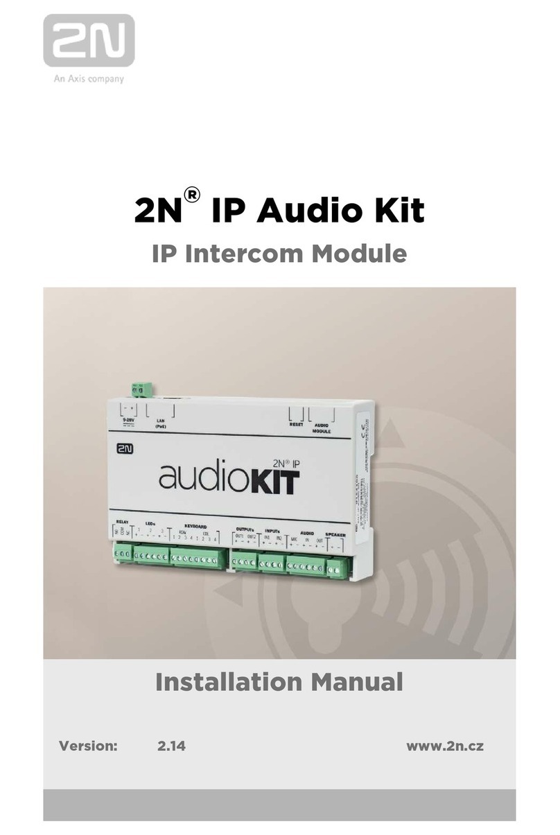
2N APS Mini Troubleshooting guide

2N APS MINI
Standalone Reader Module
Order No. 9134162WE
Reader Module
with Attendance Keypad
Order No. 9134167WE
User and Service manual
Version 2.1

2
2N APS mini System Product Range
91341611WE
EntryCom set 9134162WE
Standalone reader module 9134167WE
Reader module with attendance
keypad
91341612WE
Build-in reader module for EntryCom 91341631E
RS485/Ethernet converter 9134164E
PC mini reader
9134165E
Chip card 9134166E
Chip key fob

3
Introduction
Dear customer, congratulation on your purchase of the 2N APS mini Reader module. It is
our wish that you are fully satisfied with this product for a long time. Because it is a new
product, which is being constantly improved, any comments and proposals leading to a
better product are very welcome.
Module characteristics
The reader module is designed for simple access control/attendance registration
applications using chip cards. It is suitable for independent (autonomous) work regime, as
well as for operation within reading modules data bus. Thanks to the key pad on the
reading module it is possible to implement attendance applications that require stating a
reason before leaving the object.
Brief description of the system
System APS mini is designed for management of access and recording of attendance in
objects with up to 748 users. Identification of persons is provided by non-contact chip
cards and key rings. Its basic features include: low price, easy installation, high reliability
and minimum service and maintenance requirements.
The basic functions of the system, managing access and programming access rights, are
carried out by the reading module autonomously – without the need to be connected to the
PC. After connecting to the PC the system offers more functions – thanks to online status
monitoring and to archiving of events from the connected reading modules.
The reading module integrating all circuits necessary for one reading place and one door
is the basic hardware element of the APS mini access system.
Regimes of operation
Autonomous … programming of the database of access rights is carried out via
programming cards (“adding” and “deleting”).
Offline … programming of the database of access rights is carried out via PC. It is also
possible to configure operational parameters of the reading module.
Online … PC constantly communicates with the reading module or system of reading
modules (up to 32 modules) and stores all events in the system’s archive.
Reading module 2N APS mini can be used in all regimes of operation. Standard
accessories to the module include 2 programming cards for adding and removing user
cards without the need to connect the reading module to the PC (autonomous regime).
Software for operating the reading module via the PC in offline and online regimes can be
downloaded free of charge from the producer’s website www.2n.cz. Communication with
the reading modules via the PC requires installation of communication converter
RS485/PC to the communication line (converter RS485/RS232, RS485/USB or
RS485/Ethernet).

4
Overview of module’s features in various regimes of operation
Function Regime of operation
autonomous offline online
Definition of access rights using programming cards 999
Signalization of reading a card and releasing the door lock 999
Acoustic signalization of alarm situations 999
Changing the parameters of regimes of operation and alarms 99
Definition of access rights from the PC 99
Visualization of the regime of the reading module, recording
events in an archive in the PC, viewing and working with events
9
Controlling the output of the reading module directly from the PC
9
Technical parameters
Dimensions 105 x 90 x 20 mm
Power supply 10 ÷15 VDC
Max. power input 150 mA
ID technology EM Marin, 125kHz
Max. number of access cards in the memory 748
inputs 2x logical, non-potential
Output for door lock 1x relay switch contact 2 A / 24 V
Alarm output Transistor output 5 V / 5 mA
Protective contact (tamper) Opto-electrical
Max. reading distance Normally 8 cm with ISO cards
Communication channel RS485 galvanic non-separated
Alternative data output WIEGAND (configurable)
Signalization 2x LED + piezzo-buzzer
Working temperature -25 ÷+60°C
Max. relative humidity 95%, without condensation
Supply cable length 0,5 m
Configurable operational parameters
Parameter Possible values Default value
Lock release duration 0 ÷255 s 7 s
Acoustic signalization of lock releasing Yes / no Yes
Maximum duration of door opening 0 ÷255 s 30 s
Duration of acoustic signalization of violation 0 ÷255 s 30 s
Duration of acoustic signalization of door broken open 0 ÷255 s 30 s
Duration of acoustic signalization of door open too long 0 ÷255 s 0 s
Function of the 2nd input Leaving button /
contact handle
Leaving button

5
Installation
First drill fastening and cable holes, then insert the flat keypad cable into the reader
connector 1(when it is a keypad version), insert the enclosed square screw nut 2and
fasten the module on the wall.
It is recommended to place an installation box for connection of incoming cables on the
other side of the wall or in highly secured area (with in/out readers).
Shut the cover and lock it using enclosed screw:
Removal of the module can be performed in reverse order.

6
Recommendations for installation
Reading module 2N APS mini uses passive RF/ID technology, sensitive to external RF
disturbance. This disturbance may come via radiation from the surroundings or via supply
cables.
Therefore it is necessary to avoid installing modules close to possible sources of
electromagnetic field, including for example computer monitors (distance at least 3m) and
various home and industrial appliances. It is also better to use recommended power
supply (linear) to reduce disturbance coming via the cables.
Disturbance caused by external field is increasing with increasing intensity and with the
frequency of this field approaching the operation frequency of the reading modules (125
kHz). From this perspective it is also necessary to take into consideration mutual
disturbing of the reading modules – for proper functioning of modules it is necessary to
keep the distance of at least 50 cm. This distance can be negatively influenced by various
metallic constructions (in case of doubts it is recommended to carry out practical test on
the spot before the final installation).
Proper functioning and the reading distance can also be influenced by metal surfaces
close to the antenna. Such objects absorb electromagnetic field and may disturb the
antenna of the module – also in this case we recommend practical test.
Connecting the cables of the reading module
Description of cables
Color Purpose
Red Power supply +10 ÷ 15V
Red-blue Power supply +10 ÷ 15V
Blue 0 V
Green 0 V
Black A cable of the RS 485 line
White B cable of the RS 485 line
Pink Alarm output (+5V in case of any alarm)
Brown-green Wiegand DATA 1
Green-white Wiegand DATA 0
Yellow Input 1 (status of the door)
Grey Input 2 (leaving button / contact of the handle)
Grey-pink NC contact relay
Brown C contact relay
Violet NO contact relay
Inputs of the reading module must be controlled by a non-potential contact; the “switched
on” status is defined by the input connected to 0V.

7
Connecting the motherboard to the lock and door contacts
Contact relay for switching the door lock is lead out to the terminal board box. For standard
locks that open in response to voltage use contacts “C” and “NO”. For locks that open
when voltage disappears, while under voltage they are locked, use contacts “C” and “NC”.
Lead voltage through these contacts from the power supply to the door lock.
If there is a contact on the door, which is switched when the door is closed, lead the
contacts to the clips of input 1. Contact for monitoring the status of the door (input 1) is
taken into consideration only after the first status change after switching the module on. If
this contact is left free, the relay sets the timing for the lock always for the entire pre-
defined period and alarms “Broken open” and “Door open too long” are not generated.
Function of the input 2 can be defined as leaving button or contact of the handle. Leaving
button can be used in case of “ball-ball” door configuration for opening the door from the
inside (when leaving the building). Contact of the handle can be used with “ball-handle”
door configuration.
Connecting the mother board with data bus RS485
It is possible to connect the data line RS485 to the cables A, B and 0V. Up to 32 reading
modules 2N APS mini can be connected to this data line, which consists of three
conductors.
Data bus must be connected with cables designed for data transfer (shielded cables or
cables with twisted pairs of conductors). Modules at the end of the data bus (last module
on the line) must contain termination resistor 100 to 120 Ohm installed between cables A
and B.
Power supply for the mother board
Power supply for the mother board can be provided by the power supply of the door
communicator. The only condition is that this source must have reserve for supplying the
reading module (150 mA) and the door lock (depending on the type). Voltage rating of the
source must be 10 ÷ 15V direct current. If the current source does not comply with these
conditions, it is necessary to install a new source for the reading module.
Meaning of LED indicators
Color of LED Mode Meaning
Red
Constant shining Online communication via RS 485
Blinking with the period of 1s Offline operation
Fast alternation with green Address setting regime
Yellow Reading ID medium
Green Programming regime

8
Setting the parameters and access rights using the PC
The APS mini Reader setup program is
designed for operating systems Windows 95,
Windows NT 4.0 and higher versions; it does
not require installation. It is designed for offline
mode of the readers and allows for
programming of operation parameters on the
individual 2N APS mini modules connected on
the data bus RS485. It cannot be used for
access right programming. To connect the
modules to a PC you need either
RS485/RS232 (or alternatively RS485/USB)
communication converter with automatic
switching of the direction of communication or
an RS485/Ethernet converter with the following
settings: 8 data bits, even parity, 19 200 bps
and 1 stop bit.
The main menu of the program includes the following commands:
•Program ÆSetup … displays the screen for setup of the PC communication port and
the service card code,
•Start / Stop … PC-module communication control,
•Write … writes the configuration of the general properties in the reader module,
•Program ÆEnd … ends the program.
The program desktop is divided into 3 parts:
•The area for the reader module status visualization (used for verification of the correct
connection of the module).
•Area for HW address setup,
•Area with controls for the setup of general properties of the module.
The following indicators are located in the status line (from the left):
•PC-module communication status (red color indicates communication errors,
communication without errors is indicated by green color),
•Operation parameters writing progress,
•Verbal description of the communication status.

9
Assigning HW address
HW address of the reading modules is by default set to 1. If several reading modules are
to be connected to the communication line it is necessary that each of them is assigned a
unique address. The assigning is carried out via the communication line from the PC as
follows:
•Connect the module(s) to the communication line,
•Write the desired address into the input field “HW address”
•Press the button “Assign with the card” – the program will send request for assigning
the address, reading modules then wait c. 25 s for confirmation of the request by
reading the service card (this can be any card, whose code is entered in the field
“service card” in the program settings), waiting for the confirmation is visible on the
reader by fast double blink of the red LED in c. 2.5 sec. intervals,
•After the service card is read the program starts normal communication with the reader.
Setting operational parameters
Setting operational parameters defined in the corresponding input fields of the program is
carried out after communication was initiated and after the button “Save” was pressed.
Result of the action is shown by the progress indicator in the second part of the status bar.
Modules 2N APS mini in the online regime can be controlled via programs APS mini
Administrator, APS mini Events and APS mini ED. These allow, besides programming the
parameters of the modules, also setting access rights and monitoring various events (for
example arriving and leaving persons) and analyze them. The programs can be
downloaded free of charge from the manufacturer’s website www.2n.cz.
Functions of the explanatory keypad
Using the keypad on the reading
module enables implementing
attendance applications, which require
stating reason before leaving the
object. Key codes correspond to the
numbers on the keypad; keys F1 – F4
have codes 12 – 15. The ESC key
deletes the previously entered code
(i.e. sets the code 0). The ENTER key
has code 11.
After pressing a key the timer starts
counting c. 20 s period, after which the
code is annulled (2 short peeps).
The code is sent along with the number of the card, which was read the code is entered.
Code set for another card is annulled (code of key is set to 0).

10
Setting access rights with programming cards
Access rights for the reading modules 2N APS mini can be programmed also without the
PC thanks to two programming cards, which are part of the module delivery.
Recording cards into the memory
Step 1 Step 2 Step 3
After having read the
programming card for
recording, the reader is set to
programming regime.
Programming regime is
indicated by the yellow LED.
Read cards that are to have
access rights at the entry place
in question.
After c. 15 s after the last
card the reader will go to
the normal operational
regime by itself.
Erasing cards from the memory
Step 1 Step 2 Step 3
After having read the
programming card for erasing,
the reader is set to
programming regime.
Read cards that are to be rid of
the access rights in the entry
place in question.
After c. 15 s after the last
card the reader will go to
the normal operational
regime by itself.
Erasing all programmed cards
Step 1 Step 2 Step 3
After having read the
programming card for erasing,
the reader is set to
programming regime.
5x consecutively read the
programming card for erasing –
the reader will erase the
contents of the cards memory.
The reader will go to the
normal operation regime
by itself.

2N TELEKOMUNIKACE a.s.
Modřanská 621, 143 01 Praha 4, Czech Republic
tel.: +420 261 301 111, fax: +420 261 301 999,
e-mail: [email protected]
www.2n.cz
©2008, 2N TELEKOMUNIKACE a.s. - Praha OV 1468 v.2.1
Table of contents
Other 2N Control Unit manuals
Popular Control Unit manuals by other brands

Gemini Valve
Gemini Valve 89 Series installation instructions

Advanced
Advanced Axis AX-ASW-16 installation instructions

Elko
Elko iNels RFATV-2 quick start guide

National Instruments
National Instruments 9225 CALIBRATION PROCEDURE

Land Pride
Land Pride 380-152A installation instructions

Texas Instruments
Texas Instruments bq25600 user guide