www.atestgaz.pl
Table of contents
1 General information................................................................................................................................5
1.1 Brief description of the device...............................................................................................................5
1.2 Purpose..................................................................................................................................................5
2 Safety......................................................................................................................................................6
3 Description of the construction...............................................................................................................6
3.1 Dimension..............................................................................................................................................6
4 Input-output interfaces...........................................................................................................................7
4.1 Indication of the module status.............................................................................................................7
4.2 Current outputs 4..20 mA.......................................................................................................................7
4.3 Electric interfaces...................................................................................................................................8
5 System architectures...............................................................................................................................9
6 Life cycle................................................................................................................................................10
6.1 Transport..............................................................................................................................................10
6.2 Installation............................................................................................................................................10
6.3 Start-up................................................................................................................................................10
6.4 Configuration of the module /system...................................................................................................10
6.5 Diagnostics...........................................................................................................................................11
6.6 Periodical operations............................................................................................................................11
6.7 Utilization.............................................................................................................................................11
7 Technical specification...........................................................................................................................11
8 Product marking....................................................................................................................................12
9 Appendices............................................................................................................................................12
List of Tables
Table 1: Optical indicators status notation...................................................................................................3
Table 2: Output current in arious modes of the module operation............................................................8
Table 3: Electric interface description..........................................................................................................9
Table 4: Technical specification..................................................................................................................12
Table 5: Method of product's marking.......................................................................................................12
List of Figures
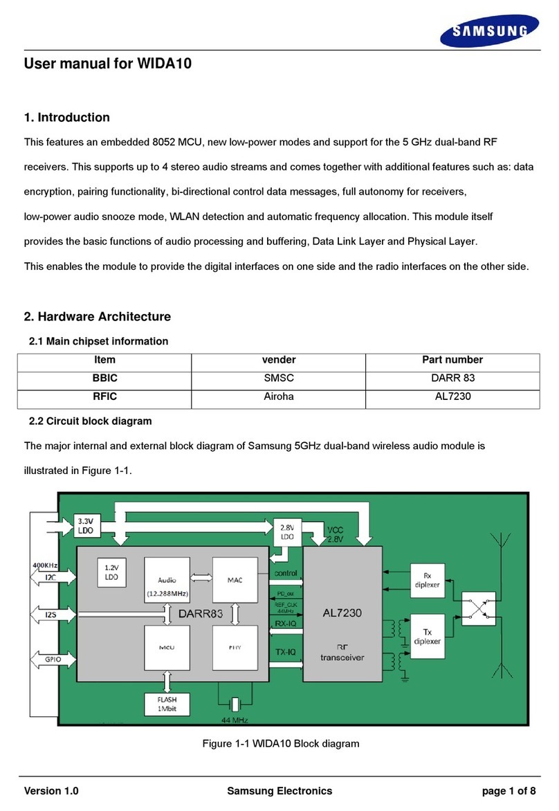
Figure 1: Structure of the Sigma MOD AO module – separation between input and output circuits............5
Figure 2: Dimension of de ice.....................................................................................................................6
Figure 3: Sigma MOD AO front panel...........................................................................................................7
Figure 4: An acti e output...........................................................................................................................7
Figure 5: A passi e output...........................................................................................................................8
Figure 6: Electric connections......................................................................................................................8
Figure 7: Example of Sigma Gas system architecture with Sigma MOD AO module.....................................9
Figure 8: Current output configuration......................................................................................................10
s. 4|12 User Manual: POD-004-ENG R01


