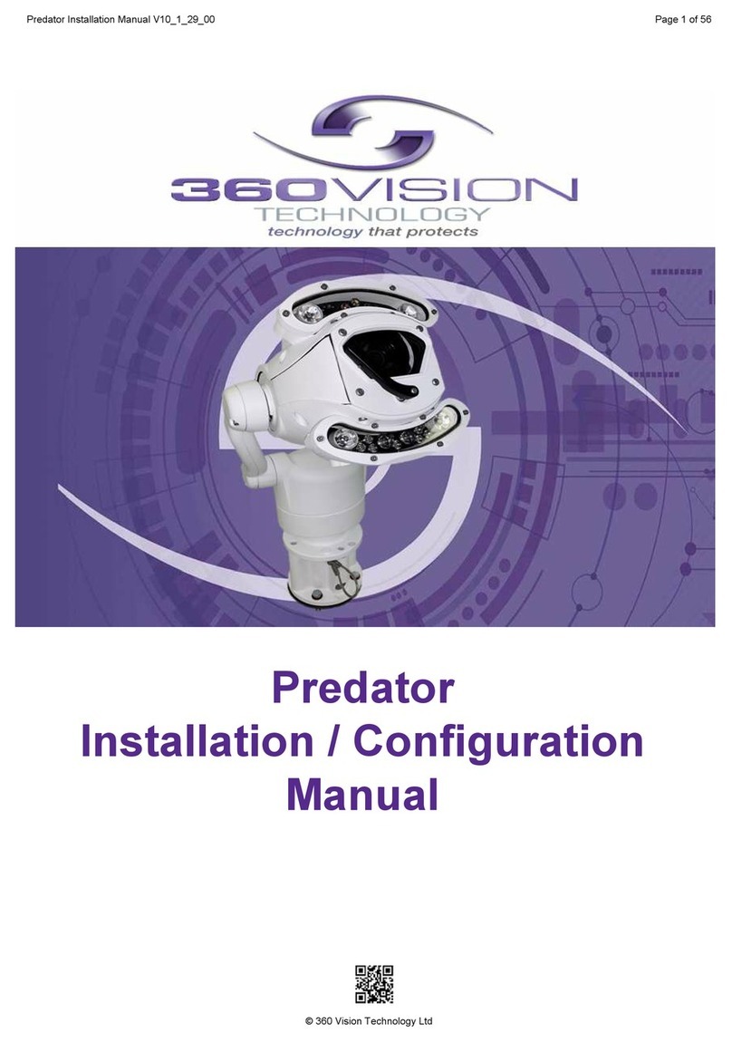
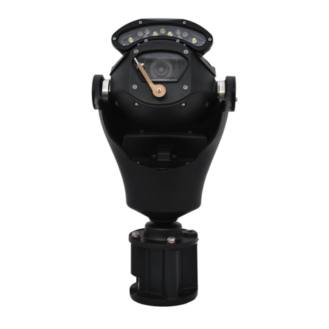
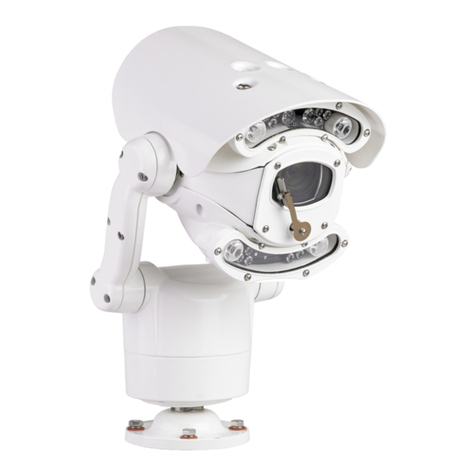
360 Vision Predator Radar Instruction sheet

Predator Radar
Installation/Conguration Manual
Predator Radar Installation Manual_V8_1_28_00
Page 1 of 78
© 360 Vision Technology Ltd
CONTENTS
1 Safety and Precautions
4
2 Housing Dimensions
5
3 PSU
6
4 Connections to Predator with HMA
7
Radar
5 Initial Connection to the Radar 12
6 Reset Network Settings 12
7 Initial Configuration 14
8 Camera Alignment 18
9 Map 20
10 Radar Position 21
11 Detection Zones 22
12 Network Settings 27
13 Radar Target Settings 28
14 Camera Settings 31
15 Detection Zone Adjustment 34
16 Date &Time 36
17 Schedule 37
18 VMS 38
19 Camera Pop up 41
20 Live Feed 42
21 Target Logs 44
22 System Logs 45
23 Maintenance 46
24 Help & Diagnostic 48
25 Operation and Performance Check 49
26 Troubleshooting 50
27 Specification 55
Camera Configuration
28 Connection to the Camera 56
29 Live view /Live Video 58
30 Status 59
Predator Radar Installation Manual_V8_1_28_00
Page 2 of 78
© 360 Vision Technology Ltd
Settings
31 - Video 60
32 - Video Advanced 61
33 - Advanced Features 63
34 - Camera 65
35 - Date / Time 67
36 - Network 68
37 - Interfaces 69
38 Add/Edit Users 71
39 Maintenance 72
40 Browser 74
41 Network Settings Recovery 74
42 Special Presets 75
43 Important - Care of Painted Surfaces 75
44 Storage and Handling 76
45 Warranty 76
46 PSU Enclosure 76
47 RTSP Links 76
48 RTSP Links Cont.… 77
49 White Balance and Fast Shutter options 77
Predator Radar Installation Manual_V8_1_28_00
Page 3 of 78
© 360 Vision Technology Ltd

1 Safety and Precautions
1. Please read these notes before attempting to operate the 360 Vision Predator Radar, and keep for future
reference.
2. DO NOT disassemble or remove covers. This will break the water seals and invalidate the warranty.
3. All servicing and repairs must be handled by 360 Vision Technology.
4. Avoid pointing the camera directly towards a bright light source (sunlight), or expose the camera to intensive
light situations as this may damage the camera pick-up device.
5. Installation should be carried out by suitably qualied personnel, in accordance with local codes of practice
and regulations.
6. 360 Vision Technology Limited accept no liability for any damage caused by incorrect or improper installation.
7. To prevent risk of injury caused by the Predator Radar or mounting options becoming detached, t a suitable
safety chain or lanyard.
8. Connection of data signals and power should only be made using a pre-made Predator Composite cables.
9. Use only 360 Vision Predator Radar power supplies. These have suitable terminals for all the wires in the
Predator composite cable.
10. Please handle the Predator Radar with care, as improper handling may cause damage within this unit.
Predator Radar Installation Manual_V8_1_28_00
Page 4 of 78
© 360 Vision Technology Ltd

2 Housing Dimensional Drawing
MUST NOT BE REPRODUCED OR SHOWN TO
DO NOT SCALE
ALL DIMENSIONS IN MM
REMOVE ALL SHARP EDGES
SHEET:
D
C
B
A
D
C
B
A
4
3
2
1
A3
DESCRIPTION
PERMISSION OF THE AUTHOR.
ANY THIRD PARTY WITHOUT THE DIRECT WRITTEN
C COPYRIGHT PROTECTED AND
THIS DRAWING AND ALL COPIES ARE
PART NUMBER:
0.200 1 OF 1
TOLERANCES:-
X = 0.5
X.X = 0.1
X.XX = 0.05 3rd ANGLE PROJECTION
360 Vision Technology Ltd.
Unit 7, Seymour Court,
Manor Park, Runcorn, Cheshire,
WA7 1SY. United Kingdom.
www.360visiontechnology.com
NAME:
M5142-B
PREDATOR RADAR DIMS
010415
DATE :
AWS
RELEASED:
APPROVED:
ENGINEER:
N/A N/A
MATERIAL: FINISH:
MUST NOT BE REPRODUCED OR SHOWN TO
DO NOT SCALE
ALL DIMENSIONS IN MM
REMOVE ALL SHARP EDGES
D
C
B
A
D
C
B
A
4
3
2
1
4
3
2
1
A3
DESCRIPTION
PERMISSION OF THE AUTHOR.
ANY THIRD PARTY WITHOUT THE DIRECT WRITTEN
C COPYRIGHT PROTECTED AND
THIS DRAWING AND ALL COPIES ARE
PART NUMBER:
0.200 1 OF 1
TOLERANCES:-
X = 0.5
X.X = 0.1
X.XX = 0.05 3rd ANGLE PROJECTION
360 Vision Technology Ltd.
Unit 7, Seymour Court,
Manor Park, Runcorn, Cheshire,
WA7 1SY. United Kingdom.
www.360visiontechnology.com
NAME:
M5141-B
PREDATOR RADAR
SUNSHIELD DIMS
310315
DATE :
AWS
RELEASED:
APPROVED:
ENGINEER:
N/A N/A
MATERIAL: FINISH:
Predator Radar with lamps and sunshield
Predator Radar with lamps & sunshield and thermal side mount.
Predator Radar Installation Manual_V8_1_28_00
Page 5 of 78
© 360 Vision Technology Ltd

MAINS FUSE
PRED-PSU-SM-HMA
MAINS FUSE = 2AF
MAINS input
100 - 240Vac
Io Vo
Adj Adj
PRED-PSU-SM-HMA
30Vdc
0V
255 x 180 x 100mm
Enclosure Dimensions
PRED-PSU-SM-HMA_v3
This PSU is compatible with the following products: PREDATOR HMA
SAFETY: Isolate mains supply while installing.
FIXING: Securely fix the PSU with suitable fixings.
GLANDS: Face downwards, unused glands must be sealed.
ELECTRICAL CONNECTIONS: Connecting the mains power.
MAINS INPUT 100-240Vac
L=LIVE (BROWN) 100-240Vac 50/60Hz
E=EARTH (GREEN/YELLOW)
N=NEUTRAL (BLUE)
SAFETY: ENSURE MAINS INPUT AND EARTH CONNECTIONS ARE SECURELY CONNECTED AND
STRAIN RELIEVED.
FUSE PROTECTION: Mains input fuse 2AF.
Model Number: PRED-PSU-SM-HMA
Serial Number: yymmndd-xxxx
Input Voltage: 100 – 240V AC 50/60Hz
Input Current: 2.1A
Output Voltage: 30V DC
Output Current: 6.2A
360Vision Technology, 7 Seymour Court Manor Park,
Runcorn, Cheshire, WA7 1SY, Tel +44 (0)1928 570000.
www.360visiontechnology.com
L
E
N
3 PRED-PSU-SM-HMA Safety and Installation Sheet
Predator Radar Installation Manual_V8_1_28_00
Page 6 of 78
© 360 Vision Technology Ltd

4 Connections to Predators with HMA
When the HMA (Hinged Mount Adaptor) is tted to the Predator, the ‘Predator Composite Cable’ is not used.
Connections between the power supply and Predator use conventional cables as detailed below.
24Vac Power connections between Predator PSU and Predator that is tted with HMA
Cable Size No IR IR75 IR100WL IR125
0.75mm² 20m 10m 7.5m 7.5m
1.00mm² 25m 12.5m 10m 10m
1.25mm² 30m 15m 12.5m 12.5m
1.50mm² 40m 20m 15m 15m
2.50mm² 65m 30m 25m 25m
3.00mm² 80m 40m 30m 30m
4.00mm² 100m 50m 40m 40m
Ethernet connections between Predator PSU and Predator that is tted with HMA.
The Ethernet connection uses standard CAT5, CAT5e or CAT6 cables tted with RJ45 connectors.
RJ45 CAT5, CAT5e, CAT6 Cable Signal
Pin 1 White with Orange Band Tx+
Pin 2 Orange Tx-
Pin 3 White with Green Band Rx+
Pin 4 Blue
Pin 5 White with Blue Band
Pin 6 Green Rx-
Pin 7 White with Brown Band
Pin 8 Brown
Gain access to connectors in the HMA
•Ensure that the xed part of the HMA is securely bolted to the top of the pole.
•The hinged part of the HMA (Hinged Mount Adapter) is fastened to the xed part using three M8x25
long hex head bolts. Use a spanner (13mm) to remove the three bolts. Each bolt is tted with a
split spring lock washer, a plain metal washer (which prevents the split washer from damaging the
bre washer) and a bre washer (which prevents the paint on the hinged part from being damaged
unnecessarily.
•Open the hinge taking care that the gasket is not damaged and support the weight of the Predator.
Gently open the HMA until the lanyard is able to take the weight. If the lanyard appears to support the
weight of the Predator, there is no need to continue to support the Predator. The connection circuit
board (PCB-000-0222-01) can now be seen.
Predator Radar Installation Manual_V8_1_28_00
Page 7 of 78
© 360 Vision Technology Ltd

Predator Radar with thermal
Connect power to (CON4) 24VAC / 30VDC
POE/Ethernet connection:
Radar connect Ethernet cable to (CON3) for
Radar power and data connection.
Thermal camera connection
Connect coax to (CON5) for video if a thermal
camera present.
Connection camera 2
This Ethernet connection is for future use
(CON2)
Connect Ethernet cable to HD HMA Predator
connection board using a RJ45 connector
(CON1)
Predator Radar with thermal PSU
Predator Radar Installation Manual_V8_1_28_00
Page 8 of 78
© 360 Vision Technology Ltd

Photo-biological safety
Lighting options:
SIR110, SIR140WL, SIR160, 250SWL
The lighting options listed above fulfil the requirements for photo-biological safety
according to IEC/EN 62471 (risk group1).
Avoid prolonged eye exposure, do not stare at operating lamp.
Lighting options:
SIR200, SIR275, SIR250WL, SIR400, SIR550S, 400SWL, SIR100W200N
The lighting options listed above fulfil the requirements for photo-biological safety
according to IEC/EN 62471 (risk group2).
Avoid prolonged eye exposure, do not stare at operating lamp.
Predator Radar Installation Manual_V8_1_28_00
Page 9 of 78
© 360 Vision Technology Ltd

Predator Radar
Installation/Conguration Section
Predator Radar Installation Manual_V8_1_28_00
Page 10 of 78
© 360 Vision Technology Ltd

Connections
Power is connected from PSU to (CON4) as shown below for predator camera.
Power –
Power +
Connect POE Ethernet cable power source to (CON3)
Thermal Camera connect coax to (CON5)
Connect Ethernet cable to (CON1) to configure the Predator Camera.
Predator Radar Installation Manual_V8_1_28_00
Page 11 of 78
© 360 Vision Technology Ltd

Ethernet Set-up
*****
I I
X
5 Initial connection to the Radar
6 Radar Network Settings - Reset to default
Predator Radar Installation Manual_V8_1_28_00
Page 12 of 78
© 360 Vision Technology Ltd

Predator Radar Installation Manual_V8_1_28_00
Page 13 of 78
© 360 Vision Technology Ltd

7 Initial Configuration
General
At power-up the Radar will enter "Target Mode" and be ready to react to suitable targets after
approximately 1 minute assuming it is already configured.
The Radar's operating parameters can be configured at any time by accessing the relevant configuration
page on the web browser.
Assuming the Radar has not already been configured, entering the Radar's IP address
(192.168.1.105
is the default) in the laptop web browser address bar will after login (where "admin" is
default username and password) bring up the Status page. Note that for most configuration pages the
Radar will still be in "Target Mode" and so respond to targets as normal. However if in the Alignment,
Detection Zones or Camera pages, then the camera will not be moved to targets to allow the user to
operate the camera undisturbed.
Most pages have help text associated with them. Hovering over the blue question mark beside a menu
item will bring up relevant help text. Some icons also have help text.
Before starting configuration for the first time make sure that the camera image can be viewed on the
laptop as some of the set-up procedures will require it.
Note 1:
To use a downloaded map to make set-up simpler, your laptop needs internet access.
Note2
: Changes made on a web-page have to be stored to the Radar using the Save or Set button on
the page
-
otherwise any changes made may be lost when you navigate away from the page or
close down the browser.
Status Page
0
Overall Radar
Status information
Disable Radar
Tick-box
Status page screenshot
The Status web page is the initial loading screen. It provides an overview of the Radar operation
including its "Overall Status", whether a schedule or detection zones are set and whether a camera is
connected or VMS set.
Predator Radar Installation Manual_V8_1_28_00
Page 14 of 78
© 360 Vision Technology Ltd

Predator Radar Installation Manual_V8_1_28_00
Page 15 of 78
© 360 Vision Technology Ltd

Predator Radar Installation Manual_V8_1_28_00
Page 16 of 78
© 360 Vision Technology Ltd

Predator Radar Installation Manual_V8_1_28_00
Page 17 of 78
© 360 Vision Technology Ltd

8 Camera Alignment - Initial Setup
Predator Radar Installation Manual_V8_1_28_00
Page 18 of 78
© 360 Vision Technology Ltd

Predator Radar Installation Manual_V8_1_28_00
Page 19 of 78
© 360 Vision Technology Ltd

9 Map - Initial Setup
Predator Radar Installation Manual_V8_1_28_00
Page 20 of 78
© 360 Vision Technology Ltd
Table of contents
Other 360 Vision Security Camera manuals

360 Vision
360 Vision Affiniti Thermal IP Instruction sheet

360 Vision
360 Vision Visiondome-VR Instruction sheet

360 Vision
360 Vision PRED-3M Instruction sheet

360 Vision
360 Vision Predator Ultra Instruction sheet

360 Vision
360 Vision Vision i Dome Instruction sheet

360 Vision
360 Vision Vision-i-Dome Instruction sheet

360 Vision
360 Vision Invictus Hybrid Instruction sheet

360 Vision
360 Vision Invictus Hybrid Manual

360 Vision
360 Vision Visiondome-HD Instruction sheet

360 Vision
360 Vision Predator Ultra Instruction sheet