360 Vision Visiondome-HD Instruction sheet

Visiondome HD Installation Manual V2.1.29 Page 1
© 360 Vision Technology Ltd.
Visiondome-HD
Installation/Conguration Manual

Visiondome HD Installation Manual V2.1.29 Page 2
© 360 Vision Technology Ltd.
Table of Contents
1 Safety and Precautions .............................................................................................................................. 3
2 Housing Dimensional Drawing ................................................................................................................... 3
3 Bracket Dimensional Drawing .................................................................................................................... 3
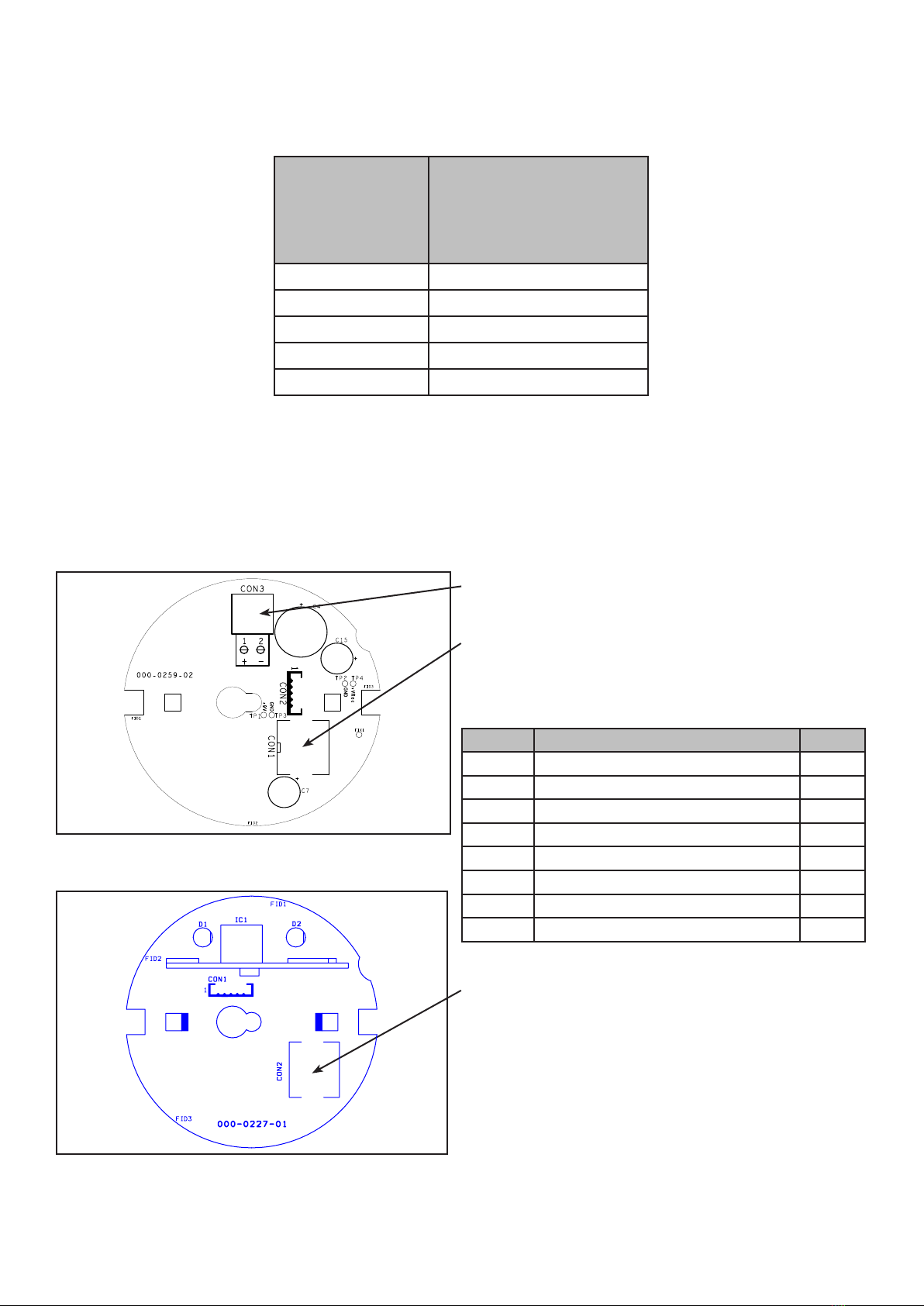
4 Connections ............................................................................................................................................... 4
5 Locating the Visiondome-HD on your Network .......................................................................................... 5
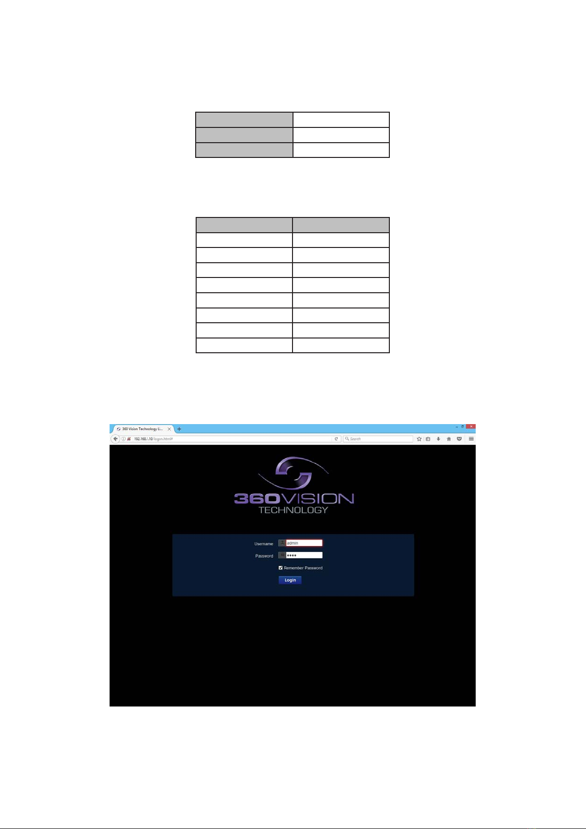
6 Connecting to the Visiondome HD ............................................................................................................. 5
6.1 Live View............................................................................................................................................ 7
6.1.1 Live Video .................................................................................................................................. 7
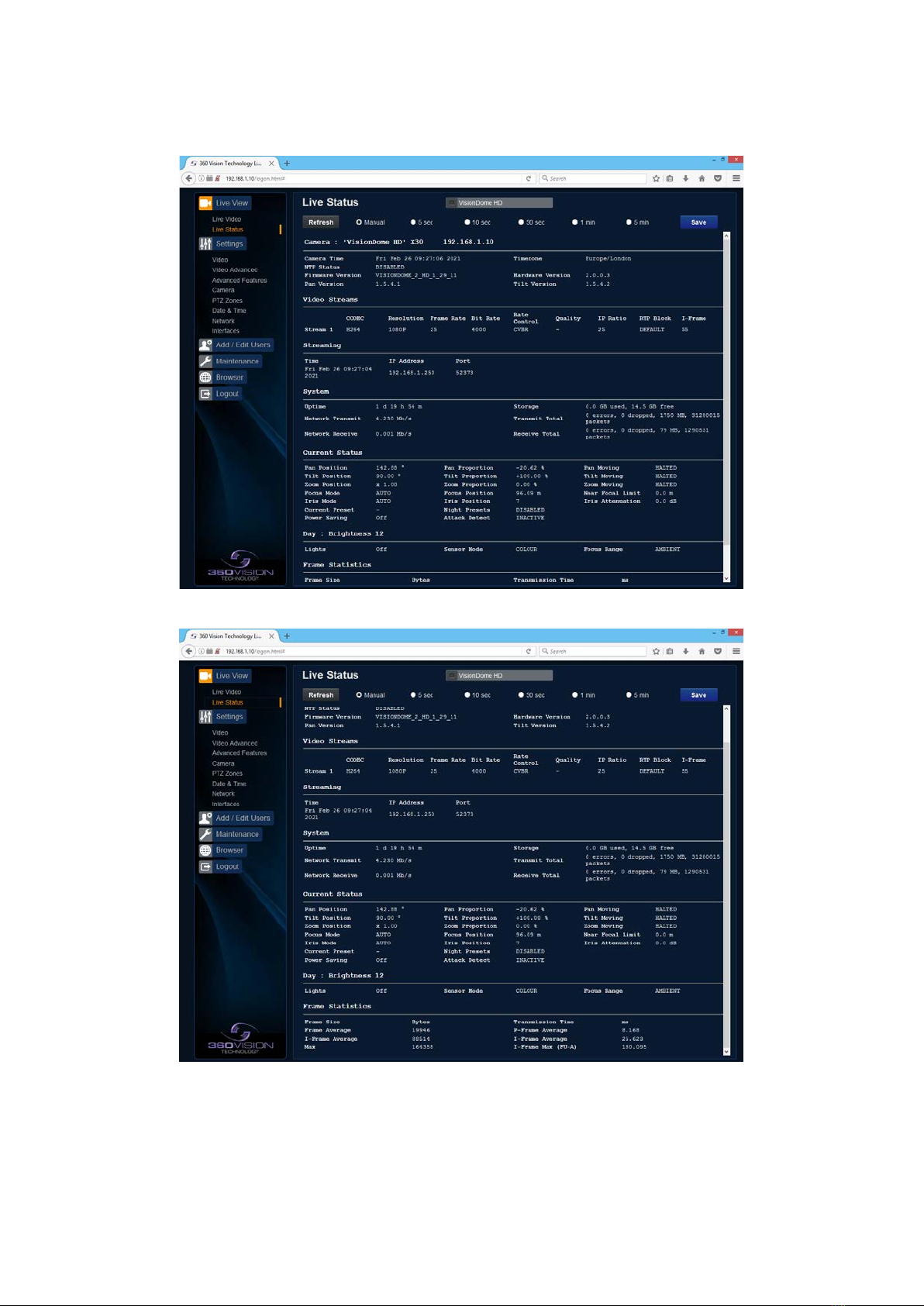
6.1.2 Status......................................................................................................................................... 8
6.2 Settings ............................................................................................................................................ 10
6.2.1 Video ........................................................................................................................................ 10
6.2.2 Video Advanced ........................................................................................................................11
6.2.3 Advanced Features .................................................................................................................. 13
6.2.4 Camera .................................................................................................................................... 15
6.2.5 PTZ Zones ............................................................................................................................... 18
6.2.6 Date/Time................................................................................................................................. 19
6.2.7 Network.................................................................................................................................... 20
6.2.8 Interfaces ................................................................................................................................. 21
6.3 Add/Edit Users ................................................................................................................................. 22
6.4 Maintenance..................................................................................................................................... 23
6.5 Browser ............................................................................................................................................ 25
7 Network Settings Recovery...................................................................................................................... 26
8 Special Presets ........................................................................................................................................ 26
9 Important - Care of Painted Surfaces....................................................................................................... 27
10 Storage and Handling............................................................................................................................. 27
11 Warranty ................................................................................................................................................. 27
12 1080p Stream Resolutions & RTSP Links.............................................................................................. 28
13 White Balance and Fast Shutter options................................................................................................ 29

Visiondome HD Installation Manual V2.1.29 Page 3
© 360 Vision Technology Ltd.
1 Safety and Precautions
1. Please read these notes before attempting to operate the 360 Vision VisionDome-HD, and keep for future
reference.
2. All servicing and repairs must be handled by 360 Vision Technology.
3. Avoid pointing the camera directly towards a bright light source (sunlight), or expose the camera to intensive
light situations as this may damage the camera pick-up device.
4. Installation should be carried out by suitably qualied personnel, in accordance with local codes of practice
and regulations.
5. 360 Vision Technology Limited accept no liability for any damage caused by incorrect or improper installation.
2 Housing Dimensional Drawing
Weight: 3.8kg Weight: 1.4kg
Internal False Ceiling Internal Pendant
3 Bracket Dimensional Drawing
LOCKING SCREW
TWIST ACRYLIC
ONTO DOME COVER
TWIST CAMERA
ONTO WALL BRACKET
AND SECURE USING
LOCKING SCREW CAMERA COVER
246 mm
Weight: 1.6kg
Internal Pole Bracket Internal Wall Bracket

Visiondome HD Installation Manual V2.1.29 Page 4
© 360 Vision Technology Ltd.
Power Connections
Connect 24Vac/30Vdc to CON3
Ethernet Connections
Connect Ethernet cable to HD Dome connection board
using a short bodied (13mm) RJ45 connector. Use colours
dened in 568B standard.
POE Ethernet Connections
Connect Ethernet cable to HD Dome connection board.
Use colours dened in 568B standard.
POE+ must support type 2.
RJ45 CAT5, CAT5e, CAT6 Cable Signal
Pin 1 White with Orange Band Tx+
Pin 2 Orange Tx-
Pin 3 White with Green Band Rx+
Pin 4 Blue
Pin 5 White with Blue Band
Pin 6 Green Rx-
Pin 7 White with Brown Band
Pin 8 Brown
4 Connections
Suitable power cables
Cable Size
Internal VisionDome-HD
(No Heater)
Maximum Distances
(Using VDI-PSU)
0.75mm² 75 metres
1.00mm² 100 metres
1.25mm² 125 metres
1.50mm² 150 metres
2.00mm² 250 metres
To ensure optimum VisionDome-HD performance these parameters must be adhered to. Failure to do so will
invalidate the warranty.
Internal VisionDome-HD Connections
Use a short bodied RJ45 connector with CAT5e cable for the connection to the VisionDome-HD PCB 000-0125-
01. Do not use RJ45 connectors with connector hoods or CAT6 cable, as these are too bulky to t properly.
The VisionDome-HD connection board is located at the top of the dome.

Visiondome HD Installation Manual V2.1.29 Page 5
© 360 Vision Technology Ltd.
Visiondome-HD Conguration
5 Locating the Visiondome-HD on your Network
Default IP Address 192.168.1.187
Subnet 255.255.255.0
Gateway 192.168.1.4
Using the DVR management software, ‘ONVIF Device Manager’ or 360 Vision Discovery Tool (which can be
found on the CD supplied or from 360 Vision Technology web site/technical support) to nd the IP address of
the Visiondome-HD. Note the ports are:-
Protocol Port
ONVIF/HTTP 80 TCP
RTP Stream 1 6970 TCP/UDP
RTCP Stream 1 6971 TCP/UDP
RTP Stream 2 6972 TCP/UDP
RTCP Stream 2 6973 TCP/UDP
RTSP 554/8554 TCP
360 SDK 3600 TCP
360 Event 9001 TCP
6 Connecting to the Visiondome HD
Type in the IP address of the Visiondome-HD into the address bar of Internet browser and install the plug-ins as
required. The web page of the camera will then appear.
Visiondome-HD Web Page Login screen
Enter the User Name (default is admin)
Enter the Password (default is 9999)

Visiondome HD Installation Manual V2.1.29 Page 7
© 360 Vision Technology Ltd.
There are six main tabs on the left of the web page/screen.
1 Live View
2 Settings
3 Add/Edit Users
4 Maintenance
5 Browser
6 Logout
6.1 Live View
6.1.1 Live Video
The Live Video page oers options to:-
• Stream - Choose required stream from drop down selection.
• 1x Display - Use to show selected stream as full screen.
• Pan/Tilt - Use the up down left and right buttons to move the camera to the desired position.
• Zoom In/Out - This will operate the optical and digital zoom (if digital zoom is enabled).
(See Camera - Digital Zoom - page 15)
• Focus Far/Auto/Near - This will operate the manual focus near, far or automatically focus as required.
(See Camera - AF AI when PTZ - page 15)
• Iris Open/Auto/Close - This will operate the manual iris open, close or automatic as required.
(See Camera - AF AI when PTZ - page 15)
• Preset Seek/Dene - This will allow admin and operator user levels to seek or dene presets (Viewer
user level can only seek presets). (See Advanced Features - Presets - page 13)
• List all Presets - Use to show all presets or programmed presets in drop down selection box.

Visiondome HD Installation Manual V2.1.29 Page 8
© 360 Vision Technology Ltd.
6.1.2 Status
Status page shows information relating to the camera status.
Status page, top section.
Status page, bottom section.

Visiondome HD Installation Manual V2.1.29 Page 9
© 360 Vision Technology Ltd.
• Save - Used to save the status page information as a HTML le.
• Refresh - Select an automatic page refresh option.
• Camera - Shows information relating to the camera time & date settings, the version of codec and
mainboard software loaded
• Video Streams - Shows the current video streams conguration.
• Streaming - Shows the IP address on the PC that is receiving the video streams.
• System - Shows how long the camera has been powered, how much bandwidth it is using etc.
• Current Status - Shows the camera function information.
• Frame Statistics - Gives information about the video stream, how big the frames are, how big the I frames
are, how long it is taking to transmit the frames.

Visiondome HD Installation Manual V2.1.29 Page 10
© 360 Vision Technology Ltd.
6.2 Settings
6.2.1 Video
The Video page, oers options to setup:-
• Camera - Add or edit the camera name.
• Stream Type - Choice of single or dual video streams.
• Codec - Choose which compression format the stream will use.
(See page 28 for table of options).
• Resolution - Set what resolution the stream will use. (See page 28 for table of options).
Stream Tabs, oer options to:-
• Framerate - Congure how many frames per second (fps) the stream uses.
(Also see Camera - Sensor Frame Rate - page 15).
• Bit Rate - Set the bit rate that the stream will use. Type in gure in Kbps. (E.g. 4000Kbps is 4Mbps)
• Rate Control - Congure the rate control of the stream, choices are VBR (Variable), CBR (Constant)
and CVBR (Constrained Variable, limited to 8Mbps).
Overlay options
• Date - Selecting this option will show the date as text on the video stream.
(See Date/Time - page 19).
• Time - Selecting this option will show the time as text on the video stream.
(See Date/Time - page 19).
• Text - Selecting this option will show the selected text on the video stream. Positions available are top
left or right of the image.
• Detailed Info - This will show the information about the stream on the video.
• Custom A - Used to enable the option to display text when the camera is operated. See options for
text selections below. Text will be shown on top line of video.
(See PTZ zones - page 18).
• Custom B - Used to enable the option to display text when the camera is operated. See options for
text selections below. Text will be shown on second from top line of the video.
(See PTZ zones - page 18).
Text selections available are
• User - For SDK use.
• Zone - Used to show text that has been programmed into the camera setup.
(See PTZ zones - page 18).
• PTZ Status - Shows camera PTZ co-ordinates.
• Camera Status - Shows the current state of the camera, what focus, iris and sensor mode the
camera is in.

Visiondome HD Installation Manual V2.1.29 Page 11
© 360 Vision Technology Ltd.
• Pan Compass - Used to display compass readings when the camera is operated.
(See PTZ zones - page 18).
• Current Preset - Used to show the stored preset text when the camera is at the preset position.
(See Advanced Features & PTZ zones - page 13 & page 18).
RTSP URL
• Copy - Use this option to copy the RTSP URL
• Date Position - Choose date text to bottom right or left of the image.
• Time Position - Choose time text to bottom right or left of the image.
• Show Sub-stream - Shows second sub-stream if enabled.
• RTSP authentication - Adds password credentials to the RTSP stream.
• D1 16:9 aspect ratio - Set D1 aspect ratio to 16:9
OK to program the new settings into the Visiondome-HD.
Cancel to abandon the changes to the video settings.
6.2.2 Video Advanced
Multicast - (See Stream Tables - page 28).
Tick the box to enable ‘multicast’. If the box is not ticked then ‘unicast’ is selected.
• Multicast Stream 1 - Set IP address and port for stream 1.
• Multicast Stream 2 - Set IP address and port for stream 2.
Concurrent Uni/Multicast - Enable to allow concurrent unicast/multicast streams.
RTSP protocols allow ‘multicast’ or ‘unicast’ transmission. In addition to the ‘multicast’ feature being available on
the Visiondome HD, the ‘multicast’ feature must also be available on the receiving device.

Visiondome HD Installation Manual V2.1.29 Page 12
© 360 Vision Technology Ltd.
Unicast
If lots of receivers (users) want to receive video streams from the Visiondome HD, each receiver will have a
separate video stream. This would increase the network bandwidth used. E.g. ve users would require ve
video streams, that typically will require ve times the bandwidth.
Multicast
If the receivers of the video streams are suitable for using ‘multicast’ and the video streams will all have the
same format, then it may be possible to use ‘multicast’. In this mode, the CODEC in the Visiondome HD
chooses a ‘new UDP address’ (Typically an address which is outside the normal range of addresses for the
network to which the Visiondome HD is connected) and sends a video stream to the ‘new UDP address’.
Multiple receivers can then access this single video stream. Consequently the bandwidth that is required by the
Visiondome HD is typically reduced to the single video stream.
When using ‘multicast’ all intermediate network-switches and routers must be set to allow the stream from the
‘new UDP address’ to be routed correctly.
Conguration
Use the below settings to set how the video is sent, adjusting the settings can help to eliminate any ‘stutter’ or
‘pulsing’ on the video image.
Stream Description
RTP Block Size 1448 (default) Range 1440 to 65500
IP Ratio 25 (default) E.g. 1 ‘i-frame’ every 25th image.
I Frame Size 55 (default) Range 0 to 99
(average frame size x value/10 = i frame size)
Unicast Stream Limit
• Used to set the unicast stream limit.
Streamer Version
• Option allows the user to set the video streamer version. Options are original and 2016a.
OK to program the new settings into the Visiondome-HD.
Cancel to abandon the changes to the advanced video settings.
Default is used to factory reset the video stream settings.

Visiondome HD Installation Manual V2.1.29 Page 13
© 360 Vision Technology Ltd.
6.2.3 Advanced Features
The Advanced Features page, oers options to:-
• Camera - Cannot be edited, shows label/name given to the camera.
(See Video - Camera - page 10).
A ‘Preset’ is a stored view. When a preset is dened, it will store the pan, tilt, zoom, focus and iris positions. Use
the up, down left and right buttons to move the camera to the desired position and then use the zoom buttons to
set the image as required.
Presets
Set Preset using the following options:-
• Number - Choose from a list of presets using the drop down box.
• Name - Edit the preset name to suit/help identify the position.
• Type - Options available are:-
Night - Allows dierent options to be used for the preset that include lamps
(See also Camera - Night Presets - page 15).
Simple - For setting a simple PTZ preset, no lamp options.
Re-Map - Choose which function/preset you want to re-map to the new preset number above.
Tour - Set the preset to start or stop a preset tour.
Mimic - Set the preset to start or stop a mimic tour.
User - Used on systems supporting 360 SDK.
Auxiliary - Can be used to recall an auxiliary command.
Power - Used to set the pan/tilt motors to use full or part power.
• Function - Function option will change to suit the above type.
• Illumination - Choice of illumination for preset with night presets function enabled. Options are IR,
White Light and o.
• Intensity - Set lamp intensity for the preset using the illumination chosen above.
• Sensor - Presets have the choice of being either colour or mono, when the scene is dark.
• Focus Range - Sets how the camera will focus when in mono. Options are ambient or IR. The Focus
Range setting will set the camera focus, (when in mono) to suit the light source in the scene.
If this is set incorrectly the image may not be in focus, when in mono at night.
• PTZ - Camera can be set to pan, tilt and zoom or not. This can be used to operate the sensor
function.
Note: This product does not have lamps tted.
!!

Visiondome HD Installation Manual V2.1.29 Page 14
© 360 Vision Technology Ltd.
• Seek - Use this to test the preset.
• Dene - Use this to set/dene the preset.
• Delete - Use this to delete/remove the preset.
Mimics
When a mimic tour is started, the Visiondome-HD will perform all the actions which were dened when the
mimic was programmed. Upto four mimic tours can be dened.
• Play - Starts the selected mimic tour.
• Start - Use this to start programming a mimic tour. Move the camera, seek presets and/or use the
lens to dene the actions to be saved for the mimic.
• Stop - Use to end the programming of the mimic tour into the Visiondome-HD.
The mimic and preset tours will repeat continuously until manually interrupted either by an alarm or user
intervention.
Tours
A tour of presets is stored in the Visiondome-HD as a list of tour points. Each tour point consists of a preset
number, the dwell time for which the Visiondome-HD will pause and the speed parameter that will be used to
seek the preset. Each of the four tours of presets can contain between 2 and 90 points.
When programming a tour of presets it is necessary to rst store all the required presets into the Visiondome-
HD and to dene the required dwell times and speeds of travel that you will require the Visiondome-HD to use
when the tour is started.
A maximum of four individual tours of presets can be stored in each Visiondome-HD. Each tour can have
between 2 and 90 points, each point can be a preset in the range 1 to 360. Dierent points can use any preset
number, including repeats of ones that have been used before. The speed that the camera will travel at to reach
the preset can be in the range 1°/sec (slowest) to 100°/sec (fastest). To seek the preset at maximum speed, set
speed to 0. The delay (dwell) at each point is dened in seconds, range 1 to 100.
• Play - Starts the selected preset tour.
• Add - Use to add a new point to the tour.
• Final - Use to indicate that this point is the last point in the tour.
Privacy Zones
A privacy zone can be used to obscure a scene with in an image e.g. private residence.
Use the drop down box to select the privacy zone preset 1 to 24. Move the camera so that the scene to be
obscured is in the centre of the image. Use zoom to set the size of the privacy zone.
• Dene - Denes the image as a privacy zone preset.
• Seek - Seeks the selected privacy zone preset.
• Enable - Sets the selected privacy zone preset as a privacy zone.
• Disable - Disables the privacy zone of the selected privacy zone preset.
Up to eight privacy zones can be viewed at the same time. The privacy zone feature is not available when the
camera is within 20° of the camera pointing vertically up or down.
Home Function
The camera will perform an action (goto preset, start preset or mimic tour), after a period of inactivity.
• Home Action - This sends the camera to a preset, tour or mimic.
• Home Number - This sets the preset, tour or mimic the camera will go to/start.
• Home Timer - This sets the time for the period of inactivity.

Visiondome HD Installation Manual V2.1.29 Page 15
© 360 Vision Technology Ltd.
PTZ buttons can be used to move the camera so that simple preset positions can be programmed or recalled.
PTZ position co-ordinates are also shown, use the refresh button to refresh the data if the camera has been
moved.
PTZ position co-ordinates can also be added manually, use the go button to send the camera to the coordinates
set.
Use the pan preset oset to set the camera to 0°, this would be used to set the camera to North if using the pan
compass option.
Use the clear button to reset the pan or tilt oset settings.
OK to program the new settings into the Visiondome-HD.
Cancel to abandon the changes to the advanced feature settings.
6.2.4 Camera
• Camera - Cannot be edited, shows label/name given to the camera.
(See Video - Camera - page 10).
The Camera page, oers options to:-
Camera Settings
• Digital Zoom - Enable digital zoom. Default is o.
• White Balance - Select White Balance settings to suit camera location.
(See page 29 for table of options).
• Wide Dynamic range - Enable WDR. Options available are ON, Auto and O. Default is o.
• Zoom speed - Select zoom speed of the lens. Options are slow, medium, high and highest.
• Proportional Zoom - Automatically reduces/increases pan/tilt speed depending on zoom ratio. Default
is on.
• Freeze Presets - This option freezes the image, when moving between presets. This can help reduce
the bandwidth. Default is o.
• Day Aperture - Can be used to increase the picture detail. Default is 10.
• Sensor Frame Rate - Can be used to set the camera to suit 25fps or 30fps. Unit must be rebooted for
settings to apply. Default is PAL.

Visiondome HD Installation Manual V2.1.29 Page 16
© 360 Vision Technology Ltd.
• Auto Focus/Iris on PTZ - Auto focus/iris will activate when PTZ is used, can be switched o. Default is
on.
• Fast Shutter - Select fast shutter if using the Visiondome-HD camera on a ANPR system. Default is
o. (See page 29 for table of options).
• Near Focal Limit - Can be used to set the near focal limit. This will help in scenes where the camera
is focusing on objects near to the camera, causing the camera to be out of focus on distant objects.
Default is 4m.
• Steady Shot - Can be used to reduce camera shake from the picture.
Steady Shot – The viewed picture is made from a window which shows part of the full picture from the camera
sensor. This means that part of the picture is wasted. The viewed part of the picture is moved automatically to
use some of the wasted part so that the observed picture is stable and has compensated for the vibrations and
minor movements of the Visiondome-HD. The maximum amount of picture stability is achieved for all zoom
settings. The part of the picture that is wasted reduces the resolution of the viewed picture when the camera is
set to 1080P and steady shot is selected. When the camera is set to 720P it is usual for no resolution to be lost
when steady shot is selected.
Stable Zoom – In this mode, when the picture is zoomed fully out (wide angle) the steady shot feature has no
eect. As the picture is zoomed out the eect of the vibrations is naturally minimized. As the picture zooms
in, the part of the picture that is viewed is a window within the whole (unzoomed) picture. The unused part of
the picture is used to allow the viewed part of the picture to be moved automatically to compensate for the
vibrations. In this mode, the viewed picture has full resolution for all of the zoom range, but the camera does not
compensate for the vibrations when the picture zoom is at or near to the fully zoomed out setting.
Extended Zoom – This option doesn’t produce a steady picture, instead of which, a window within the whole
picture is viewed i.e. the scaling of the picture is altered slightly which gives the advantage that the normal 30x
zoom has been extended to 36x zoom. This is eectively a digital zoom and as such, when 1080P is used, the
resolution of the picture has been slightly reduced. When the camera is set to 720P it is usual for full resolution
to be achieved for the full range of zoom settings.
• Exposure Oset - Used to set the camera exposure setting.
• Zoom Wide Limit - Used to set the camera zoomed out limit (physical power reset required to apply
changes).
Night Settings
• Night Changeover - Night Changeover settings can be changed to suit the site requirements. Options
are dark, medium, light and custom. Default is dark. This sets when the camera goes into ‘dark
mode’.
• Custom On Level - Range is 7 to 25. A lower value will set the level on when the scene is brighter, a
higher value will set the level on when the scene is darker. Default is 7.
• Custom O Level - Range is 1 to 20. A lower value will set the level o when the scene is brighter, a
higher value will set the level o when the scene is darker. Default is 1.
• Night Brightness - This controls the exposure compensation, by articially brightening the image.
Options are normal and auto. Default is normal.
• Night Sensor - Can be set to colour or mono. Default is mono.
• Night Focus Range - Sets how the camera will focus (when in mono) to suit the light source in the
scene. If this is set incorrectly the image may not be in focus.
• Night Focus Sensitivity - This can be set to normal or low. When it is set to low the method used to
focus the camera is suited to low light conditions. Default is low.
• Night Aperture - Can be used to increase the picture detail. Default is 3.
• Night Noise Reduction - Used to reduce noise with scenes of low illumination. NR must be set to suit
the environment. Default is 1.
• Night Presets - This can be used to set the presets to dierent settings if required. Default is on.
(See Advanced Features - page 13).
• Dim Lights Angle - Feature not available.
• Dim Lights Intensity - Feature not available.
• Night HLC Level - Set a value to help mask high intensity light sources, options are low, medium and
high.
• Night HLC Mask - Sets a mask for the light source, options are 1 (white) to 15 (grey).
!!

Visiondome HD Installation Manual V2.1.29 Page 17
© 360 Vision Technology Ltd.
Conguration
• Sun Shield - Feature not available.
• Auto Flip - Use this option to set how the camera behaves when full tilt down is reached.
Tilt - Requires a second tilt down command, when at full tilt down to spin camera 180°.
Limit - Automatically spins the camera 180° when full tilt down is reached.
• Attack Detect - Feature not available.
• Upright Mount - Can be used to ip the image, so the camera can be used on a pole or a ceiling.
Default is ceiling.
• Power on Park - When the camera powers up, it will go to a preset position. Preset 150. Default is o.
• Pan/Tilt Speed - Can be used to set the pan/tilt speed. Options are Normal, 20%, 40%, 60%, 80%
Slower, 20%, 40%, 60% or 80% Faster. Default is normal.
• Status Refresh Rate - Can be used to help speed up telemetry control of the camera, by slowing
down the refresh rate.
• Static PTZ Mode - Disables all PTZ functions.
• Power Saving - Reduces power to to the motors while the unit is static. Full power returns when the
unit receives a PTZ command.
Lighting (Visiondome-HD Feature not available)
• White Lamps - Set if white lights are to be used.
• White Timer - Set white light timer.
• Exclusion Zones- Option to be used if a white light exclusion area is to be used, set area using
presets 151 (left) & 152 (right), IR light exclusion area is required, set area using presets 153 (left) &
154 (right) or white & IR light exclusion zone.
• Auto Dimming - When selected the camera will reduce the lamp power, when looking in scenes
where there is to much light.
OK to program the new settings into the Visiondome-HD.
Cancel to abandon the changes to the camera settings.

Visiondome HD Installation Manual V2.1.29 Page 18
© 360 Vision Technology Ltd.
6.2.5 PTZ Zones
The PTZ zones page, oers options to:-
• Camera - Cannot be edited, shows label/name given to the camera.
(See Video - Camera - page 10).
Set Text Overlays using the below options (see also Video - page 10):-
• 1-16 - Set up to 16 text overlays.
• Pan - Used to set pan axis as the trigger for the text overlay to be displayed.
• Tilt - Used to set the tilt axis as the trigger for the text overlay to be displayed.
• Start Preset - Set start preset for text overlay.
• End Preset - Set end preset for text overlay
• Text - Input required text for sector zone overlay.
PTZ buttons can be used to move the camera so that simple preset positions can be programmed or recalled.
PTZ position co-ordinates are also shown, use the refresh button to refresh the data if the camera has been
moved.
PTZ position co-ordinates can also be added manually, use the go button to send the camera to the coordinates
set.
• Preset Seek/Dene - This will allow admin and operator user levels to seek or dene presets (Viewer
user level can only seek presets). (See Advanced Features - Presets - page 13)
• List all Presets - Use to show all presets or programmed presets in drop down selection box.
OK to apply the new settings into the Visiondome-HD.
Cancel to abandon the changes to the PTZ zones settings.

Visiondome HD Installation Manual V2.1.29 Page 19
© 360 Vision Technology Ltd.
6.2.6 Date/Time
• Camera - Cannot be edited, shows label/name given to the camera.
(See Video - Camera - page 10).
• Camera Time - Cannot be edited, shows the current date and time of the camera.
• Date Format - Select from the drop down the date format.
• Time Format - Choose 24hr or 12hr time display.
Set Time
The Date/Time page, oers options to:-
• Set Manually - Input time/date manually.
• Synchronize with Computer Time - Put a tick in the button and then click OK, to apply the local
computer date/time to the camera.
• Synchronize with NTP Server - Put a tick in the button and then click OK, to apply the local server
date/time to the camera.
• NTP Server - Input the address of the time server required, default is pool.ntp.org.
Time Zone
• Time Zone - Select time zone to suit the location of the camera.
OK to apply the new settings into the Visiondome-HD.
Cancel to abandon the changes to the date/time settings.

Visiondome HD Installation Manual V2.1.29 Page 20
© 360 Vision Technology Ltd.
6.2.7 Network
• Camera - Cannot be edited, shows label/name given to the camera.
(See Video - Camera - page 10).
Network
The Network tab, oers options to:-
• DHCP Enable - Allows the camera to be set using a dynamic IP address.
• IP Address - Input a static IP address, if DHCP is not used.
• Netmask - Input the Network Subnet Mask.
• Default Gateway - Input the Network Gateway.
• Primary Name Server - Input the Domain name server, if required.
• MTU Size - Option to change the MTU size, default is 1500 bytes.
• MAC Address - Displays the camera MAC address.
• Default Recovery - Disables the Network recovery process
(See Network Settings Recovery - page 26)
NTP
• NTP Server - Input the address of the time server required, default is pool.ntp.org.
Quality of Service
• Best Eort - Will send network packets with no quality of service policies.
• Expedited Forwarding - Will send network packets with an assured bandwidth quality of service
policy.
• Custom - Input required Hex gure for quality of service policy
• Best Eort = 0x00
• Expedited Forwarding = 0x2E
Web Server
• HTTP access - Enable or disable HTTP access, must be connected using HTTPs.
(See Maintenance - SSL Key/Certicate - page 23)
• HTTPS Port - Set required HTTPs port. Default is 443.
• SSL Certicate - Choose required SSL certicate.
• SSL Private Key - Choose required private key.
Table of contents
Other 360 Vision Security Camera manuals

360 Vision
360 Vision Affiniti Thermal IP Instruction sheet

360 Vision
360 Vision Predator-Dualview Manual

360 Vision
360 Vision Eclipse HD Stainless Steel Instruction sheet

360 Vision
360 Vision Vision i Dome Instruction sheet

360 Vision
360 Vision Predator Ultra Instruction sheet

360 Vision
360 Vision Predator Radar Instruction sheet

360 Vision
360 Vision Invictus Hybrid Instruction sheet

360 Vision
360 Vision Predator Ultra Instruction sheet

360 Vision
360 Vision Vision-i-Dome Instruction sheet

360 Vision
360 Vision PRED-3M Instruction sheet