360 Vision Invictus Hybrid Manual

V12_1_129_03
Page 1 of 49
© 360 Vision Technology Ltd

Table of Contents
1
Safety and Precautions .............................................................................................................................. ... 3
2
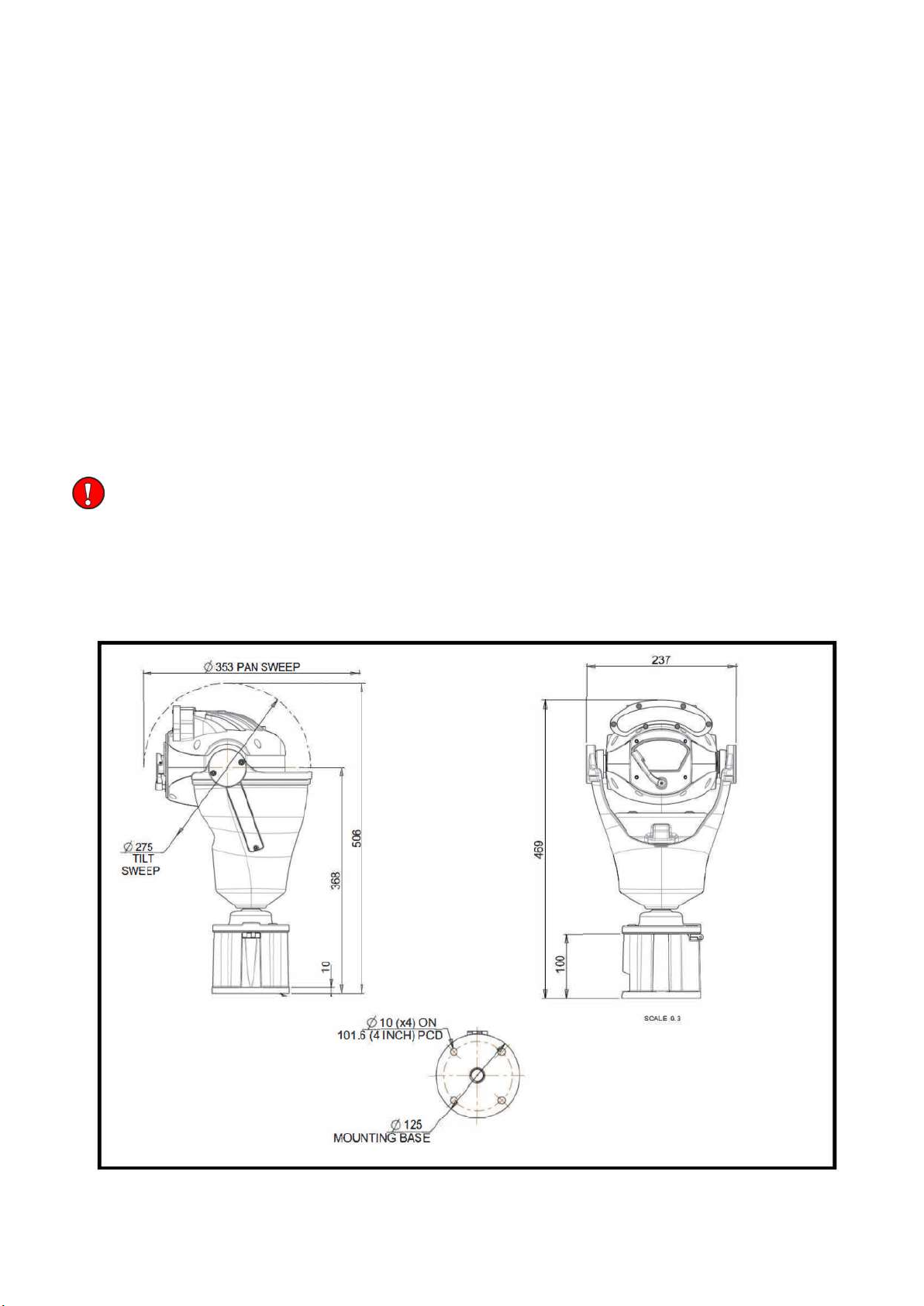
Housing Dimensional Drawing .....................................................................................................................3
3
Bracket Dimensional Drawing .......................................................................................................................4
4
Connections ............................................................................................................................................... ...5
4.1 Standalone Alarm card Setup ..........................,. .....................................................................................7
5 Invictus Washer/Nozzle Bracket..............................,. ..................................................................................11
6 Connections 1D Invictus with HMA ....................................................................................................................12
7
Basic Twisted Pair/RS485 Data wiring ...................................................................................................... 15
8
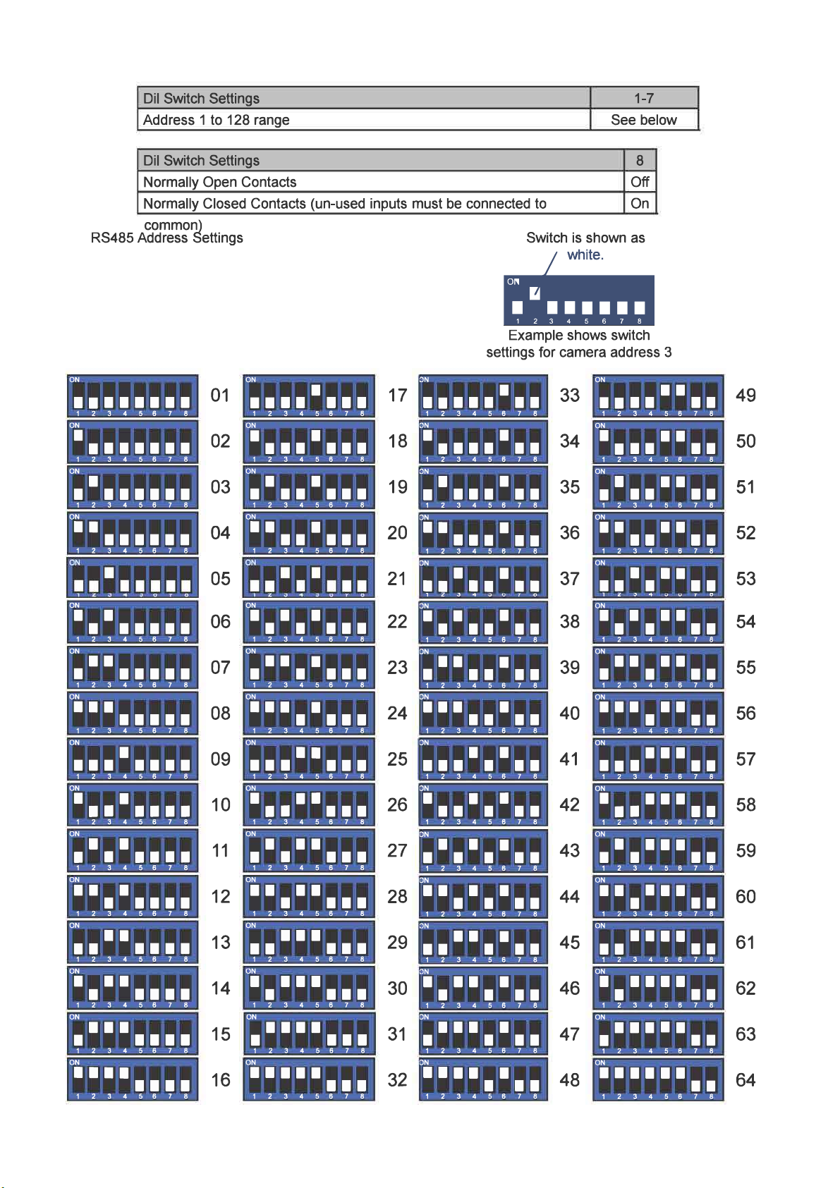
Invictus Protocol/Address setup ................................................................................................................. 15
9
Invictus OSD .............................................................................................................................................. 16
9.1 PIN Number ......................................................................................................................................... 16
10
OSD Operation/Navigation ...................................................................................................................... 17
11
Locating the Invictus Hybrid on your Network ........................................................................................... 24
12 Connecting to the Invictus Hybrid.............................................................................................................. 24
12, 1 Live View ............................................................................................................................................ 26
12.1.1
Live Video ..................................................................................................................................... 26
12.1.2
Status .................................................................................................................................. ......... 27
12.2
Settings ..................................................................................................................................... 28
12.2.1
Video ............................................................................................................................................. 28
12.2.2 Video Advanced ....................................,. ..................................................................................... 29
12.2.3 Advanced Features ...............................,. ..................................................................................... 31
12.2.4 Camera .................................................,. ..................................................................................... 33
12.2.5 Date/time ............................................................................................................................... 35
12.2.6 Network .................................................,. ..................................................................................... 36
12.2.7 Interfaces ............................................................................................................................ .......... 37
12.3
Add/Edit Users ...................................................................................................................................... 39
12.4
Maintenance ......................................................................................................................................... 40
12.5
Browser ........................................................................................................................................ ......... 41
13 Network Settings Recovery ...................................,. ................................................................................. 42
14
Special Presets ................................................................................................................................... ...... 43
15
Important - Care of Painted Surfaces ....................,. ................................................................................ 43
16
Storage and Handling ............................................................................................................................... 44
17
Warranty .................................................................................................................................................... 44
18
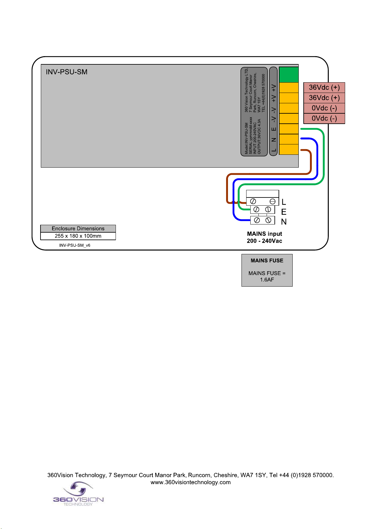
PSU Enclosure .......................................................................................................................................... 44
19
1080p Stream Resolutions
&
RTSP Links.................................................................................................44
20
White Balance and Fast Shutter options .................................................................................................. 45
21
White Balance Photo Biological Safety Precaution .................................................................................... 46
22
Recording and recording browser ............................................................................................................. 47 -48
V12_1_129_03
Page 2 of 49
© 360 Vision Technology Ltd

1 Safety and Precautions
1.
Please read these notes before attempting to operate the 360 Vision lnvictus Hybrid, and keep for future reference.
2.
DO NOT disassemble or remove covers. This will break the water seals and invalidate the warranty.
3.
All servicing and repairs must be handled by 360 Vision Technology.
4.
Avoid point the camera direct towards a bright light source (sunlight), or expose the camera to intensive light
situation as this may damage the camera pick-up device.
5.
Installation should be carried out by suitably qualified personnel, in accordance with the local codes of practice and
regulations.
6.
360 Vision Technology Limited accept no liability for any damage caused by incorrect or improper installation.
7.
To prevent risk of injury caused by the lnvictus hybrid or mounting options becoming detached, fit a suitable safety
chain or lanyard.
8.
Use only 360 Vision lnvictus Hybrid power supplies. These have suitable terminals for all the wires in the lnvictus
composite cable.
9.
Please handle the lnvictus Hybrid with care, as improper handling may cause damage within this unit. ***** Photo
Biological Safety Information (See page 46)
M8 bolts (HMA) need to be tightened to 11 Nm
2 Housing Dimensional Drawing
lnvictus HMA with LED Array
V12_1_129_03
Page 3 of 49
© 360 Vision Technology Ltd

3. Bracket Dimensional Drawing
Invictus Wall Bracket
Invictus Corner Bracket
Invictus PMB Bracket
V12_1_129_03
Page 4 of 49
© 360 Vision Technology Ltd

This PSU is compatible with the following products: Invictus
SAFETY: Isolate mains supply while installing.
FIXING: Securely fit the PSU with suitable fixings.
GLANDS:Face downwards, unused glands must be sealed.
ELECTRICAL CONNECTIONS:Connecting the main power.
MAININPUT 200-240VAC
L=LIVE (BROWN) 200-240VAC 50/60Hz
E=EARTH (GREEN/YELLOW)
N=NEUTRAL (BLUE)
SAFETY: ENSURE MAINS INPUT AND EACH CONNECTION ARE SECURELY CONNECTED AND STRAIN
RELIEVED
FUSE PROTECTION: MAINS UNPUT FUSE 1.6AF
4. Connections
INV-PSU-SM Safety and installation sheet
V12_1_129_03
Page 5 of 49
© 360 Vision Technology Ltd

This PSU is compatible with the following products: Invictus
SAFETY: Isolate mains supply while installing.
FIXING: Securely fit the PSU with suitable fixings.
GLANDS:Face downwards, unused glands must be sealed.
ELECTRICAL CONNECTIONS:Connecting the main power.
MAININPUT 200-240VAC
L=LIVE (BROWN) 200-240VAC 50/60Hz
E=EARTH (GREEN/YELLOW)
N=NEUTRAL (BLUE)
SAFETY: ENSURE MAINS INPUT AND EACH CONNECTION ARE SECURELY CONNECTED AND STRAIN
RELIEVED
FUSE PROTECTION: MAINS UNPUT FUSE 1.6AF
INV-XALARM-PSU-SM Safety and installation sheet
V12_1_129_03
Page 6 of 49
© 360 Vision Technology Ltd

The INV-XALARM-PSU has eight normally open/closed (Dilswitch S1, switch 8 on) alarm inputs on connector CON1
on the alarm PCB, When using normally closed contacts, all unused alarm inputs musty be connected to the alarm in
common CON 1. Connect switches or volts free relay outputs from PIRs or other equipment to CON1 connector is
activated. There is also an alarm relay which can be used to activate alarm s on other equipment (DVR etc) The
Alarm relay contacts (Common - 'C'. Normally Open - 'NO' are Normally Close - 'NC') use connector CON3 on the
alarm PCB.
When an alarm is activated, the ALARM PCB will activate the alarm relay output and will send commands to set the
lnvictus to activate 'alarm mode'. The lnvictus will save the current status (pan, tilts, lens, tour and mimic) then it will
seek the preset which corresponds with the active alarm number.
1 1
2 2
8 8
The alarm will remain active while the alarm input is active. After the alarm input becomes inactive, a 10 second
alarm timer will start. The timer extends the alarm activity until the alarm timer expired. If the alarm input becomes
active again before the timer has expired, the timer resets and will restarts again when the alarm input comes
inactive and a further preset seek command is sent to the lnvictus
If an alarm is active and a further alarm becomes active, the latest alarm will interrupt the previous alarm. (I.e. the
latest alarm as highest priority) The lnvictus will seek the preset that corresponds with the new alarm. When contact
become inactive, the lnvictus will seek the preset that corresponds with the previous highest priority alarm that is still
active. When all alarms inputs are inactive the alarm timer starts. After the timer expires, the Alarm PCB sends a
commands to the lnvictus to end the 'alarm mode' and the lnvictus will return to the status position and action that
has been saved when first alarm became active (Fit a link on the alarm card COM4 position 7 to disable the
automatic return to the pre· alarm status when all alarms and the alarm time have expired)
When an alarm is active and the lnvictus has automatically selected the appropriate preset, it is possible
to send further commands (i.e. Manual control) to the lnvictus which will override the preset which had
previously been automatically selected. Each time an automatic preset seek occurs as described in the
previous paragraph; the manual control will be interrupted.
4.1 Standalone Alarmcard Setup
Protocol/Alarm settings
Use CON4 to set protocol and camera
alarm behavior (see page 9)
Power Connections
Connect Power 30Vdc to CON7
RS485 Out Connections/LK1 termination
Connect RS485 to camera to CON5
Relay Output
Use CON3 for relay output.
Alarm Inputs
Use CON 1 for volt free alarm inputs
Address (1-7) (Range 1 to 128)
Use Dilswitch to set address same as camera.
(See Page 8)
Alarm Input setting
Use Dilswich pole 8 to set if alarms are N/0 or N/C. All
unused N/C contacts to be connected to alarm common.
(See Page 8)
RS485 In Connections/LK3 termination
Connect RS485 from controller to CON6
V12_1_129_03
Page 7 of 49
© 360 Vision Technology Ltd

V12_1_129_03
Page 8 of 49
© 360 Vision Technology Ltd

V12_1_129_03
Page 9 of 49
© 360 Vision Technology Ltd

MAINS FUSE
MAINS FUSE =
1.6AF
INV-PSU-SM Safety and Installation Sheet
360Vision Technology, 7 Seymour Court Manor Park, Runcorn, Cheshire, WA7 1SY, Tel +44 (0)1928 570000.
www.360visiontechnology.com
200 - 240Vac
0Vdc (-)
0Vdc (-)
36Vdc (+)
36Vdc (+)
This PSU is compatible with the following products: Invictus
SAFETY: Isolate mains supply while installing.
FIXING: Securely fit the PSU with suitable fixings.
GLANDS:Face downwards, unused glands must be sealed.
ELECTRICAL CONNECTIONS:Connecting the main power.
MAININPUT 200-240VAC
L=LIVE (BROWN) 200-240VAC 50/60Hz
E=EARTH (GREEN/YELLOW)
N=NEUTRAL (BLUE)
SAFETY: ENSURE MAINS INPUT AND EACH CONNECTION ARE SECURELY CONNECTED AND STRAIN
RELIEVED
FUSE PROTECTION: MAINS UNPUT FUSE 1.6AF
V12_1_129_03
Page 10 of 49
© 360 Vision Technology Ltd

Water Jet direction (Vertical)
Adjustable Nozzle
Tie
Tube
Nozzle Bracket located
Fit M8 Plain Washer Between Nozzle bracket and
Invictus mounting base.
V12_1_129_03
Page 11 of 49
© 360 Vision Technology Ltd

The Invictus is fitted with a HMA (Hinged Mount Adapter) this enables the camera to be fitted on a 4"PCD
mount then by removing the 3 x HMA bolts carefully hinged over to rest on the fitted lanyard. Cables can then
be entered into the camera via either of the 2 gland holes (side or underneath) with a fitted 20mm gland, the
supplied 360 blanking grommet must be fitted to the hole not used. Once all cables are terminated carefully
hinge the unit back over and tighten the 3 HMA bolts back up to compress the gasket down.
Recommended Cable Diameter/Distance (Exceeding these will cause the Invictus to not work)
Camera current draw table
6 Connections to Invictus with HMA
V12_1_129_03
Page 12 of 49
© 360 Vision Technology Ltd

Ethernet connections between lnvictus PSU and lnvictus that is fitted with HMA.
The Ethernet connection uses standard CAT5e or CAT6 cables fitted with RJ4S connectors
RJ4S
Tx+
Rx+
Gain access to connectors in the HMA
Ensure that the fixed part of the HMA is securely bolted to the top of the pole.
The hinged part of the HMA (Hinged Mount Adapter) is fastened to the fixed part using three M8X2S long hex head
bolts. Use a spanner (13mm) to remove the three bolts. Each bolt is fitted with a split spring lock washer, a plain metal
washer (which prevents the split washer from damaging the fiber washer) and a fiber washer (which prevents the paint
on the hinged part from being damaged unnecessarily.
Open the hinge taking care that the gasket is not damaged and support the weight of the lnvictus. Gently open the
HMA until the lanyard is able to take the weight. If the lanyard appears to support the weight of the lnvictus, there is no
need to continue to support the lnvictus. The connection circuit board (PCB-000-0262-
xx) can now be seen.
Analogue Camera output
Use BNC for analogue video output
Power Connection
Connect Power to CON5 (22-28VAC - 22-36VDC)
RS485
Connection
Use CON7 to connect the RS48S twisted pair data.
Washer
Connection
(If feature is present) Use CON6 to connect washer signal to
lnvictus washer PSU (PCB-000-0240-xx) CON9
Ethernet Connections
Connect Ethernet cable to HD HMA lnvictus connection board
using a RJ45 connector (CON4)
Please make sure there is adequate spare cable (20cm) for when the camera is resting on the lanyard, failure to do this
could damage the connector circuit board.
V12_1_129_03
Page 13 of 49
© 360 Vision Technology Ltd

MAINS input
100 - 240Vac
L
N
E
MAINS FUSE
MAINS FUSE = 1.6AF INV-POE-PSU_V2
Data In
Data &
Power Out
RJ45
CONNECTION
TO CAMERA
RJ45
CONNECTION
TO NETWORK
255 x 180 x 100mm
Enclosure Dimensions
INV-POE-PSU Safety and Installation Sheet
PLEASE NOTE - The recommended POE PSU is IEEE802.30bt 90w compliant.
Any deviation will not be guaranteed and we recommend we supply the POE PSU
with all POE Predator models.
This PSU is compatible with the following products: Invictus
SAFETY: Isolate mains supply while installing.
FIXING: Securely fit the PSU with suitable fixings.
GLANDS:Face downwards, unused glands must be sealed.
ELECTRICAL CONNECTIONS:Connecting the main power.
MAININPUT 200-240VAC
L=LIVE (BROWN) 200-240VAC 50/60Hz
E=EARTH (GREEN/YELLOW)
N=NEUTRAL (BLUE)
SAFETY: ENSURE MAINS INPUT AND EACH CONNECTION ARE SECURELY
CONNECTED AND STRAIN RELIEVED
FUSE PROTECTION: MAINS UNPUT FUSE 1.6AF
Connect Ethernet cable only
V12_1_129_03
Page 14 of 49
© 360 Vision Technology Ltd

I
V12_1_129_03
Page 15 of 49
© 360 Vision Technology Ltd

V12_1_129_03
Page 16 of 49
© 360 Vision Technology Ltd

Controller Level Operator Level
lnvictus OSD
(On screen display) is accessed by defining / programming preset 6 & 95.
•
Use the joystick up, down, left, right, to navigate the menu.
•
Use the joystick zoom in to highlight / select an option.
•
Use joystick left and right to increment/decrement numbers
C
V12_1_129_03
Page 17 of 49
© 360 Vision Technology Ltd

Engineer Level Pin Numbers
Operators: 360 or 426 or 180
Controllers: 1379 or 9731
Engineers: 5498
V12_1_129_03
Page 18 of 49
© 360 Vision Technology Ltd

1O OSD Operation / Navigation
Dome menu
•
Seek Preset
•
Start Tour
•
Start Mimic
•
Dome Settings Menu
Define Tour
A tour of presets is stored in the lnvictus as a list of tour points. Each tour point consists of a preset number, the dwell
time for which the lnvictus will pause and the speed parameter that will be used to seek the preset. Each of the four
tours of presets can contain between 2 and 90 points.
When programming a tour of presets it is necessary to first store all the required presets into the lnvictus and to define
the required dwell times and speeds of travel that you will require the lnvictus to use when the tour is started.
A maximum of four individual tours of presets can be stored in each lnvictus. Each tour can have between 2 and 90
points, each point can be a preset in the range 1 to 300. Different points can use any preset number, including repeats
of ones that have been used before. The speed that the camera will travel at to reach the preset can be in the range
1°/sec (slowest) to 100°/sec (fastest). To seek the preset at maximum speed, set speed to 0. The delay (dwell) at each
point is defined in seconds, range 1 to 100.
This page will open on Tour 1, use the joystick left and right to change to another tour. To add item 1, use the joystick
to tilt down. This will highlight the number line so that the tour can be programmed. Use the joystick to navigate along
the number line and zoom in to select the number. This will add the number in to the NEW tour. Add in the figures for
the item/point in the tour using the sequence labeled above (PREDELSPD. PRE is preset position, DEL is delay in
seconds and SPD is speed
at °/second). This is how the camera will be programmed to move to a preset for a period of time at a set speed. All
nine figures must be added into the item. Figures must be added in three for example pre set 21 will be added as 021.
021005100 = Move to preset 21 for 5 seconds at 100°/sec
Highlight ACCEPT ITEM and zoom in, this will add the item/point into the tour. The OLD item/point will be shown on
the screen. If these settings are acceptable, highlight the ACCEPT ITEM option and zoom in. There is no need to add
in these points again. Keep adding points until the tour is complete. On the final item/point of the tour highlight and
zoom in on ACCEPT FINAL ITEM. This will complete the tour programming.
Define Mimic
(Before going into the OSD screen to program
a
Mimic tour it is recommended to move the
camera in to the start position, any movement or delay will be recorded once the recording has started.)
When a mimic tour is started, the lnvictus will perform all the actions which were defined when the mimic was
programmed. Up to four mimic tours can be defined.
Highlight and zoom in on START RECORDING, this will allow a mimic tour to be programmed into the camera. The
mimic tour can then be used to playback any manual movement, preset seek or delay. Program a preset to end the
mimic tour program.
Define Preset
Before going into the OSD screen to program a preset, the camera must be in the position required. Once in the OSD
you cannot manually move the camera.
Define Home Function
The camera will perform an ACTION (goto preset, start preset or mimic tour), after a period of inactivity.
Use the NUMBER option to set which preset or tour to start, and the DELAY MINUTES/SECONDS to input the
inactivity time period.
V12_1_129_03
Page 19 of 49
© 360 Vision Technology Ltd

Settings Menu Set-Up
•Auto Flip - Use this option to set how the camera behaves when full tilt down is reached.
oSemi - Requires a second tilt down command when at full tilt down to spin camera 180°.
oFull - Automatically spins the camera 180°
•Power on Park - When the camera powers up, it will go to a pre-set position. Pre-set 150. Default is off
•Attack detect - Camera will re-initialize camera motors so that the camera looks back to the original position, if the camera
is physicaly foreced / moved. Default is off.
•Upright Mount - Can be used to flip the image, so the camera can be used on a pole or a ceilling. Default is pole.
•Sun Shield - N / A not applicable on Invictus model.
•IR Lens option - WID option will use the smaller wider area of illumination for the IR and the NAR will use the bigger IR but
will be a more centralized area of illumination.
Settings Menu Pelco-Aux
•
AUX- Used when using Pelco protocol auxiliary commands. Associate a function of the camera to a Pelco Aux command.
Options of auto focus, digital zoom, auto iris, ir, wiper, washer, osd, backlight, white light, auto icr, fast shutter, ir-mono,
mono, park 150, low power, spare 1.
Settings Menu Zoom/Pre sets
•
Digital Zoom - Use this option to enable or disable digital zoom.
•
Proportional - Automatically reduces/increases pan/tilt speed depending on zoom ratio
•
Zoom Speed -The range of speed 5 to 8 and 8 being the fast zoom to slow down the zoom change to 5.
•
AF Al When PTZ - Auto focus/iris will activate when PTZ is used, can be switched off. Default is on.
•
Freeze Pre-sets - This option freezes the image, when moving between pre sets
•
Define Pre-set - Option to enable/disable the setting of pre-sets. Default is on
•
OSD Pre-set
six-
Go into OSD using pre-set 95 and you can switch off OSD access using pre-set 6
Settings Menu Wiper
•
Wiper Rest - Input a rest time for the wiper
•
Wiper on Time (h) - Input a time period for the wiper operation
•
Wiper on Time (m) - Input a time period for the wiper operation
•
Wiper on Time (s) - Input a time period for the wiper operation
•
Wiper Permanent - Enable or disable the permanent wiper time period.
Settings Menu Protocols
•
Pelco D Response
-Used on systems using Pelco D protocol where a response from the camera is required.
Do not use if the system doesn't require a response as it
will
have an effect on the telemetry control of the cameras
•
Pelco Static Mode -Disables PTZ control
•
FV White Lights - Used when using Forward Vision protocol, can be used to select what lamps are controlled from the
lamp command
V12_1_129_03
Page 20 of 49
© 360 Vision Technology Ltd
Other manuals for Invictus Hybrid
1
Table of contents
Other 360 Vision Security Camera manuals

360 Vision
360 Vision Visiondome-VR Instruction sheet

360 Vision
360 Vision Affiniti Thermal IP Instruction sheet

360 Vision
360 Vision Predator Radar Instruction sheet

360 Vision
360 Vision Predator Ultra Instruction sheet

360 Vision
360 Vision Vision i Dome Instruction sheet

360 Vision
360 Vision Visiondome-HD Instruction sheet

360 Vision
360 Vision Predator-Dualview Manual

360 Vision
360 Vision Invictus Hybrid Instruction sheet

360 Vision
360 Vision Predator Ultra Instruction sheet

360 Vision
360 Vision Eclipse HD Stainless Steel Instruction sheet