manuals.online logo
Brands
  1. Home
  2. •
  3. Brands
  4. •
  5. 3B SCIENTIFIC PHYSICS
  6. •
  7. Laboratory Equipment
  8. •
  9. 3B SCIENTIFIC PHYSICS 1023095 User manual

3B SCIENTIFIC PHYSICS 1023095 User manual

3B SCIENTIFIC®PHYSICS
1
Franck-Hertz Tube with Hg Filling and Heating Chamber
1023095 (230 V, 50/60 Hz)
1023094 (115 V, 50/60 Hz)
Instruction sheet
10/21 ALF/ SD/ GH
1. Safety instructions
The apparatus conforms tothesafety regulations for
electrical test, control and laboratory equipment as
specified inDIN EN 61010Part 1. Itsprotectionclas-
sification is deemed to be class I. It is intended for
use in dry rooms suitable for electrical equipment or
installations.
Safe operation of the equipment is guaranteed,
provided it is used correctly. However, there is no
guarantee of safety if the equipment is used in an
improper or careless manner. If it is deemed that
the equipment can no longer be operated without
risk (e.g. visible damage has occurred), the
equipment should be switched off immediately
and secured against any inadvertent use.
In schools and training institutions, operation of the
apparatus is to beresponsiblysupervised by trained
personnel.
Beforeputtingtheequipmentintooperation,con-
firm it is compatible with the local mains voltage.
Before setting up or starting any experiments,
check the apparatus for any damage.
In the event of any malfunction/defect or visi-
ble damage, switch off the equipment imme-
diately and secure it against any inadvertent
use.
The instrument may only be connected to the
mains via a socket that has an earth connec-
tion.
Only trained electricians are permitted to
open up the apparatus’ housing.
Beware: Risk of burns! The viewing windows and
the walls of the heating chamber can reach tem-
peratures of up to 300° C during operation.
Set up the heating chamber on a heat-re-
sistant surface.
When the heating chamber is in operation, do
not attempt to touch or move the apparatus.
Only move or transport the equipment by us-
ing the insulated handle.
Allow the apparatus to cool before disman-
tling the experiment.
Beware: There is always a risk that glass can
break and cause injury.
Use all six knurled screws to affix the front
plate to the heating chamber.
Do not subject the tube to any mechanical
stress. Do not put kinks in any connecting
leads.
2
The Franck-Hertz tube contains mercury.
If the glass breaks and mercury escapes,
make sure to observe safety regulations re-
lating to the handling of mercury.
2. Description
The Franck-Hertz tube with its mercury filling is
used to demonstrate the quantised release of en-
ergy by free electrons colliding with mercury at-
oms and to determine that the excitation energy
for the mercury resonance line (61S0–63P1) is 4.9
eV.
Franck-Hertz tube attached to front plate
The Franck-Hertz tube is a highly evacuated elec-
tron tubecontainingmercurywithitselectrodes set
up in parallel planes. The electrodes consist of an
indirectlyheated oxidecathode, an anode grid and
a collector electrode. In order to increase the like-
lihood of collisions, the distance between the an-
ode and cathode has been made large (8 mm) in
comparison to the mean free path in a mercury at-
mosphere (for a temperature of approx. 180°C).
By contrast, the distance between anode and col-
lector is small. An earth ring is located level with
the anode grille to prevent disturbance due to
background radiation. The tube is mounted on the
front plate of the heating chamber and can be re-
moved or exchanged. The front plate also has ce-
ramic-insulated sockets and a schematic diagram
of the tube. The Franck-Hertz tube is mounted in
such a way that the whole tube and its connecting
wires can all be maintained at constant tempera-
ture. This is necessary because the density of the
mercury vapour is always determined at the cold-
est point of the tube. Leakage currents resulting
from radiation due to ion conduction in the hot
glass walls are prevented by a protective sintered
alumina ring. A fixedattenuating resistor (10 is
inserted between the sockets for the accelerating
voltageandfortheanodeofthetube.Thisprotects
the tube in the event of excessive voltage occur-
ring due to arcing. The voltage drop across this re-
sistor can be neglected when measurements are
being made.
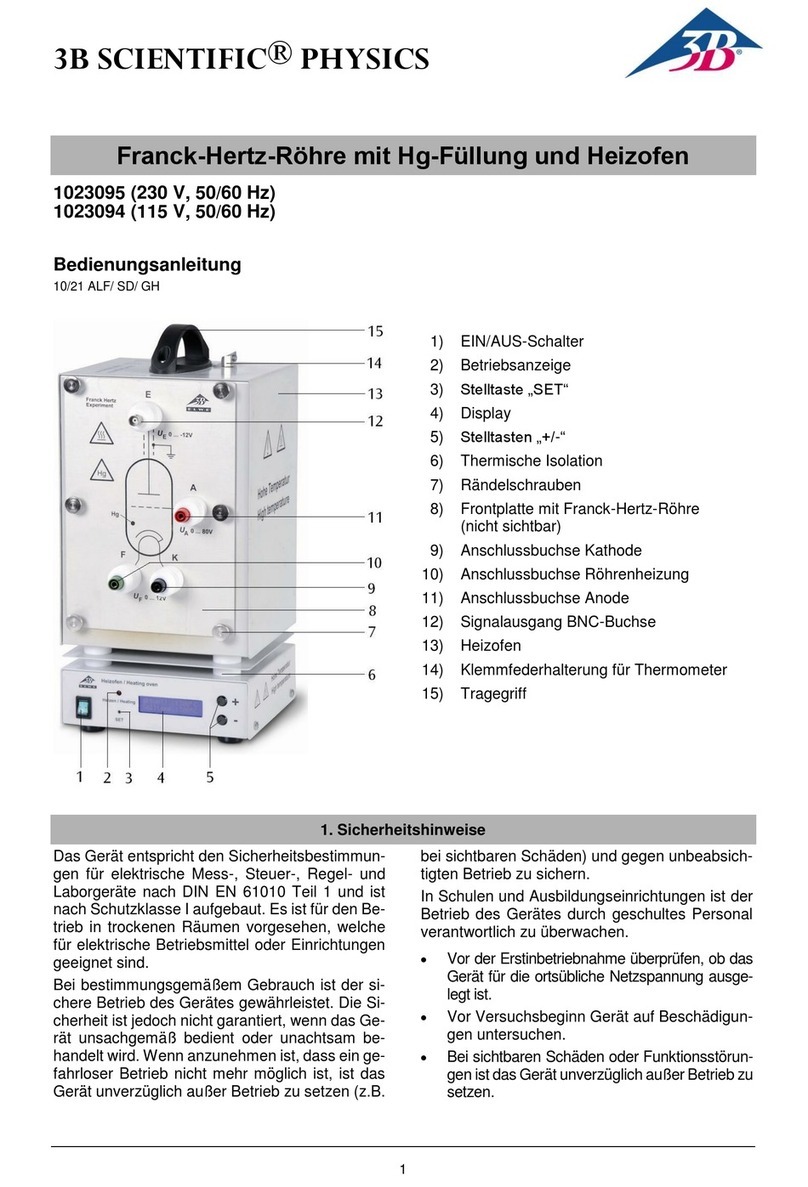
Heating chamber
The heating chamber serves to establish the va-
pour pressure inside the Franck-Hertztube with its
mercury filling and helps you carry out experiments
with a sodium fluorescence tube (1000913).
It consists of a powder-coated sheet steel casing
with two viewing windows. The front plate is at-
tached via six knurled screws. The chamber is
heated via a tubular heating element in the cham-
ber floor. Temperature measurement and regula-
tion is carried via an integrated micro-controller
and a PT 100 thermocouple. A digital tempera-
ture display allows you to read off the tempera-
ture set-point and the actual temperature value.
The “SET” button can be used to toggle the dis-
play between ° Celsius and ° Fahrenheit. The “+/-
” keys allow you to set the set-point for the tem-
perature in steps of 1 K. There is an opening at
the top with a spring clip for holding a thermometer
and a thermally insulated carrying handle.
The apparatus 1023094 is for operation with a
mains voltage of 115 V (±10%), and the unit
1023095 is for operation with a mains voltage of
230 V (±10%).
2.1 Scope of delivery
1 Franck-Hertz tube with mercuryfilling mounted
on front-plate
1 Heating chamber without front plate
1 Instruction sheet
1 Power switch 2 Operating display
3 “SET” button 4 Display
5 “+/-” buttons 6 Thermal insulation
7 Knurled screws 8 Front plate with Franck-
8 Hertz tube attached (not
8 shown)
9 Cathode socket 10 Tube filament socket
11 Anode socket 12 BNC socket for signal
12 output
13 Heating chamber 14 Spring clip for thermom-
eter
15 Handle
3
3. Technical data
Franck-Hertz tube
Filament: 4 to 9 V AC/DC
Grid voltage: 0 to 80 V
Bias voltage: 1.5 V approx.
Operating temperature: 160°C - 200° C approx.
Tube dimensions: 160 mm x 30 mm diam.
Weight: 380 g approx.
Heating chamber
Mains voltage: See back of case
Dimensions of front
opening: 230 x 160 mm² approx.
Heating power: 800 W @230 V
400 W @115 V
Maximum temperature: 300°C @230 V
250°C @115 V
Temperature constancy: ±1°C approx.
Dimensions: 335x180x165 mm³ ap-
prox.
Weight: 5.6 kg approx.
4. Operation
The following equipment is also required to com-
plete the experiment:
1 Power supplyunit for F/H experiment @230 V
1012819
or
1 Power supply unit for F/H experiment @115 V
1012818
1 Digital oscilloscope, 2x 30 MHz 1020910
1 HF Patch cord, 1 m 1002746
2 HF Patch cords, BNC/4 mm plug 1002748
Safety leads for experiments 1002843
Note: Before switching on, remove the PE
packaging part, which is located behind
the tube, from the inside of the heating
oven.
Place front plate of the open side of the heat-
ing chamber and fix it in place with 6 knurled
screws.
Turn off the heating chamber and the control
unit to begin with and turn all the knobs on the
control fully to the left.
Do not apply an accelerating voltage to
the tube when it is still cold (the mercury
inside may cause a short circuit).
Connect terminals "A", "F" and "K" (refer to fig.
2).
Connect terminal "E" of the Franck-Hertz
tube to the correct input on the control unit by
means of an BNC cable.
Connect the “FH Signal UY-out” terminal of
the control unit to the Y input of the oscillo-
scope and terminal “UX” to the X input.
Turn on the control unit and the equipment
should enter ramp mode.
Slowly set a filament voltage of 6 V. The indi-
rectly heated cathode requires about 90 sec-
onds to warm up, once the voltage is applied.
Turn on the heating chamber. Set a tempera-
ture of about 180° C and wait for the tube to
warm up (about 5 to 10 minutes).
Set the minimum acceleration voltage to
zero, slowly increase the maximum accelera-
tion voltage to 80 V.
Do not, however, increase the accelerating
voltage so much that self-discharge no longer
occurs inside the tube. Any ionisation due to
collisions will disrupt the curve.
Set up the oscilloscope initially with settings
of x = 1 V/div and y = 1 V/div.
Observe the emergence of the maxima in the
Franck-Hertz trace on the oscilloscope
screen.
Set up all the parameters, accelerating volt-
age, cathode filament, bias voltage and am-
plitude so that a trace with nicely delineated
maxima and minima is obtained.
The procedure as described so far is a gen-
eral setting procedure. Unavoidable differ-
ences resulting from the manufacture of indi-
vidual Frank-Hertz tubes mean that the opti-
mum parameters may differ from tube to tube.
The test report included with the tube should
give some idea of where good results may be
obtained for the tube in question.
The collector current displays regularly recurring,
equidistant maxima and minima that are inde-
pendent of the accelerating voltage. The interval
between these peaks is 4.9 V. A contact potential
of 2 V exists between the anode and cathode of
the tube, which is why the first maximum only ap-
pears in the region of 7 V. The first maxima will be
more obvious when the temperature of the heat-
ing chamber is lower.
Evaluation of the Franck-Hertz curve:
To fully evaluate the Franck-Hertz curve, a digital
voltmeter is needed. This does not require that
the current of the electron beam be determined
precisely. The oscilloscope screen should show
the trace of a Franck-Hertz curve featuring very
clear maxima and minima.
4
Connect a digital voltmeter between the sig-
nal output (UX) and the ground socket (refer
to fig. 3).
Press the “Man/Ramp” button and the display
will show “Man” to indicate manual mode.
Turn the accelerating voltage knob all the
way to the left (UA= 0 V).
The display will show the accelerating voltages in
steps of 0.5 V. In order to obtain better test re-
sults, a digital voltmeter can be connected be-
tween sockets "A" and "K" in order to obtain a
more accurate measure of the accelerating volt-
age.
Note: The accelerating voltage is reduced by a
factor of 10 at the signal output (UX). The digital
voltmeter, however, measures the full accelerat-
ing voltage between sockets “A” and “K”.
By gradually increasing the accelerating voltage
at a constant rate, the precise position of the
maxima and minima can be determined with the
aid of the digital voltmeter.
Curve optimization
Fig. 5: Illustration of various signals of the Franck-
Hertz tube.
The parameters of the tube can change during
the use of the tube. This usually happens either
due to ageing of the tube or due to the experi-
mental specification. Figure 5.f) represents the
ideal example of the curve. However, other types
of curves can also occur.
Breakdown of the tube:
Figure 5.a) shows the case of a breakdown of the
tube. The anode current increases rapidly to a
maximum value. In this case, the accelerating
voltage must be lowered immediately. If it should
be necessary to map further maxima, the temper-
ature of the furnace must be increased before-
hand.
Optimization of the countervoltage:
Figures 5.b) and 5.c) show a too steep or too flat
curve with few maxima. The countervoltage de-
termines the slope of the curve. The greater the
countervoltage, the flatter the rise. In combination
with the acceleration voltage, the quality of the
maxima can be slightly improved.
Optimization of the filament voltage:
The filament voltage determines the number of
emitted electrons and thus the anode current.
The higher the filament voltage, the more elec-
trons are emitted. Figure 5.d) shows the case
where the anode current is too high. The signal
flattens out to a horizontal line above a threshold
value. The maximum number of available elec-
trons is reached (under the given filament volt-
age) and the anode current remains constant, de-
spite the increasing accelerating voltage. Figure
5.e) shows the case of a too low filament voltage.
The signal has a low rise and the maxima are
weak, although there is a sufficiently high number
of maxima. In these cases, lowering or increas-
ing the filament voltage is often sufficient to ob-
tain an evaluable curve. Note: An excessively
high filament voltage has a negative effect on the
life of the tube. It is not recommended to operate
the tube with too high filament voltages.
5. Care and maintenance
Before cleaning the equipment, disconnect it
from its power supply.
Use a soft, damp cloth to clean it.
5
6. Disposal
The packaging should
be disposed of at local
recycling points.
Should you need to dis-
pose of the equipment it-
self, never throw it away
in normal domestic
waste. Local regulations
for the disposal of elec-
trical equipment will ap-
ply.
If Frank-Hertz tubes are
to be disposed of, local
regulations applying to
the disposal of mercury
must be followed.
Fig. 1 Schematic of set up for measuring the Franck-Hertz curve for mercury (C cathode, G grid, A collector elec-
trode)
Fig. 2: Experiment set-up for Franck-Hertz tube with Hg filling
F
KG A
E
XY
+
-
E
F K
A
3B Scientific GmbH ▪ Ludwig-Erhard-Str. 20 ▪ 20459 Hamburg ▪ Germany ▪ www.3bscientific.com
Subject to technical amendments
© Copyright 2021 3B Scientific GmbH
Fig. 3 Experiment set-up for Franck-Hertz tube with 2 digital voltmeters
Fig. 4 Franck-Hertz curve
F
KG A
E
+
-
E
F K
A
XY

Other manuals for 1023095

1

This manual suits for next models

1

Other 3B SCIENTIFIC PHYSICS Laboratory Equipment manuals

3B SCIENTIFIC PHYSICS 1000762 User manual

3B SCIENTIFIC PHYSICS

3B SCIENTIFIC PHYSICS 1000762 User manual

3B SCIENTIFIC PHYSICS U19171 User manual

3B SCIENTIFIC PHYSICS

3B SCIENTIFIC PHYSICS U19171 User manual

3B SCIENTIFIC PHYSICS U8431776 User manual

3B SCIENTIFIC PHYSICS

3B SCIENTIFIC PHYSICS U8431776 User manual

3B SCIENTIFIC PHYSICS ELWE U8400830 User manual

3B SCIENTIFIC PHYSICS

3B SCIENTIFIC PHYSICS ELWE U8400830 User manual

3B SCIENTIFIC PHYSICS 1009934 User manual

3B SCIENTIFIC PHYSICS

3B SCIENTIFIC PHYSICS 1009934 User manual

3B SCIENTIFIC PHYSICS 1018466 User manual

3B SCIENTIFIC PHYSICS

3B SCIENTIFIC PHYSICS 1018466 User manual

3B SCIENTIFIC PHYSICS U10362 User manual

3B SCIENTIFIC PHYSICS

3B SCIENTIFIC PHYSICS U10362 User manual

3B SCIENTIFIC PHYSICS 1023095 User manual

3B SCIENTIFIC PHYSICS

3B SCIENTIFIC PHYSICS 1023095 User manual

Popular Laboratory Equipment manuals by other brands

Agilent Technologies 6500 Series Maintenance Guide

Agilent Technologies

Agilent Technologies 6500 Series Maintenance Guide

Exsys EX-60315 manual

Exsys

Exsys EX-60315 manual

VERDER Carbolite Gero HTCR 5/220 Installation, operation and maintenance instructions

VERDER

VERDER Carbolite Gero HTCR 5/220 Installation, operation and maintenance instructions

Beckman Coulter FP 1000 manual

Beckman Coulter

Beckman Coulter FP 1000 manual

Thermo IEC FRENCH Press FA-078A Operation manual

Thermo IEC

Thermo IEC FRENCH Press FA-078A Operation manual

Metrohm 6.5330.210 manual

Metrohm

Metrohm 6.5330.210 manual

DIVERSIFIED WOODCRAFTS 3116K Assembly instructions

DIVERSIFIED WOODCRAFTS

DIVERSIFIED WOODCRAFTS 3116K Assembly instructions

Leica RM2125RTS Standard operating procedure

Leica

Leica RM2125RTS Standard operating procedure

Encore ENNPOE-I user manual

Encore

Encore ENNPOE-I user manual

Baoding Longer Precision Pump EasyPump Series manual

Baoding Longer Precision Pump

Baoding Longer Precision Pump EasyPump Series manual

Shodex C18-4D Operation manual

Shodex

Shodex C18-4D Operation manual

Optigene Genie III user manual

Optigene

Optigene Genie III user manual

BANDELIN SONOREX DIGITEC User instructions

BANDELIN

BANDELIN SONOREX DIGITEC User instructions

Hach TenSette 19700-01 manual

Hach

Hach TenSette 19700-01 manual

NUVE NC 300 user manual

NUVE

NUVE NC 300 user manual

Thermo Scientific Dionex ICS-5000 Operator's manual

Thermo Scientific

Thermo Scientific Dionex ICS-5000 Operator's manual

Affymetrix GeneChip 645 Quick reference card

Affymetrix

Affymetrix GeneChip 645 Quick reference card

Aqua Ultraviolet Classic Series Replacement

Aqua Ultraviolet

Aqua Ultraviolet Classic Series Replacement

manuals.online logo
manuals.online logoBrands
  • About & Mission
  • Contact us
  • Privacy Policy
  • Terms and Conditions

Copyright 2025 Manuals.Online. All Rights Reserved.