3D AEROWORKS Extra 500 Guide

Assembly manual
and user guide
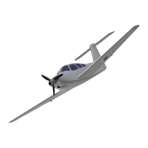
Extra 500
By 3D AEROWORKS

OVERVIEW:
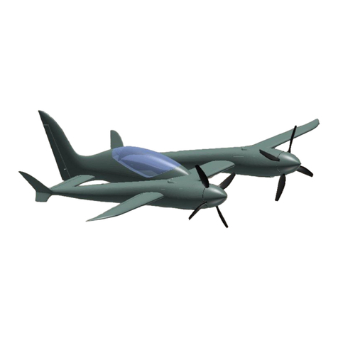
This replica of the Extra 500 turbo-prop executive cruiser is designed for quick
and easy construction and printed using PLA. A semi-scale propeller and hub
is included in the plans designed to suit the 3536 1400kv outrunner in 2 or 4
blade configuration. Utilising full 5 channel controls; aileron, elevator, rudder,
flap and throttle. This model performs extremely well given its lightweight
design. Links to components used can be found on the last page of the user
guide.
GENERAL SPECIFICATIONS
WINGSPAN: 1000mm
PRINT WEIGHT: 790g
FLYING WEIGHT: 1100g - 1200g
ELECTRICS
MOTOR: 3536 1400kv
ESC: 50amp (recommended)
SERVOS: 9g
BATTERY: 2200MAH 3S (or similar)
INCLUDED
STL FILES OF ALL COMPONENTS
FACTORY FILES FOR SIMPLIFY 3D FOR PRINTERS: 200X200X200
**NOTE**
If using open source or free slicing software, scale all stl parts to 1000%
to attain proper sizing. Factory files for S3D have been scaled
appropriately

REQUIRED TOOLS:
KNIFE
SANDPAPER (MEDIUM GRIT)
PLIERS
CA GLUE
SCREW DRIVERS
FILE OR RASP
HOT GLUE GUN
DRILL
REQUIRED COMPONENTS:
X1 3536 1450KV motor (or similar)
X1 60AMP ESC
X1 2200MAH 3S LIPO (or similar)
X6 9g Sservo
X2 10mm X10mm X 2mm magnet (ROUND)
X14 16mm x 29mm nylon hinges
X4 M3 16mm screws
X2 M6 nylon bolt (length 30mm)
X2 M6 nylon nut
X2 1.2mm push rod (MIN LENGTH = 500mm)
x1 5x3mm carbon tube (OPTIONAL)
X1 3mm square carbon tube (50mm min length)
x1 1.2mm Linkage stopper
x1 m3 set screw
x3 45mm foam wheel (OPTIONAL)
Velcro
1mm push rod
3mm steel rod (x2 200mm + x1 95mm)

ASSEMBLY INSTRUCTIONS
1
All faces which are to be glued to other parts need to be given a light sanding
(scuff the surface) to assist with glue adhesion
FUSELAGE ASSEMBLY
2 (if using fixed gear, follow alternate steps 2a before continuing)
Glue the sections of the fuselage together using CA glue. With a sharp knife,
remove the floor of the battery hatch. (see pic, highlighted face in red)

2A
● Glue the nose gear washers in the slots provided in “fuse 2”.
external washer (smaller) internal washer (larger)
● Run a 3mm drill bit through the washers for the nose gear leg.
● Bend up a 95mm length of 3mm steel rod according to the following
diagram.
FRONT VIEW
● Fit a 1.2mm Linkage stopper to the steering arm.

● Install the nose gear leg with the steering arm and another m3 collar
locking the nose gear leg in the slot. (The hole in the side of the
steering arm is designed for a m3 set screw to secure the steering arm
to the gear leg, note- the hole should be pre-drilled with a 2.5mm drill
bit)
SIDE VIEW
TOP VIEW
● Glue fuse 2,3 and 4 together.
● Connect the steering arm to a length of 1.2mm wire and feed it through
the assembled fuse section. There is a small hole in the battery tray
floor to get a key through to adjust the wire on the steering arm.

3
Using either a soldering iron or 6mm drill bit, open up the holes in the top of
the fuse where the wing bolts will go through to connect with the nylon bolts.
(area to be removed highlighted in red)
Fit the nylon nuts into the slots provided at the rear wing join. secure with hot
glue or CA. (be careful not to fowl the thread with any glue)
TAIL ASSEMBLY
4
Glue the parts; “vertical stabiliser lower rear” and “vertical stabiliser middle
front” together using 3mm sections of skewer to align the parts. NOTE - leave
enough skewer protruding to align the top of the vertical stabiliser when it
comes time to fit it.
5

Glue the horizontal stabilisers to the vertical stabiliser assembly using 3mm
skewer.
6
Cut a 50mm section of 3mm square carbon tube and glue the elevators,
carbon tube and elevator control arm in place as shown. (note the position of
the control arm reference to the elevators)
7

Run a 1.2mm length of push rod up the vertical stabilser, connect it to the
elevator control arm and test fit the elevator assembly movement.
Once staisfied, glue it in place.
8
Glue the “vertical stabiliser middle rear” to the tail assembly, followed by the
“vertical stabiliser tip”.
Finally glue the “vertical stabiliser lower front” to the tail assembly and fit the
tail to the fuselage using the 3mm skewers to align the parts. be sure that the
tail is level and square.
9
Run a 1.2mm length of push rod through the remaining bowden tube and
connect up the rudder.
Note- if using fixed gear, connect the wires according to the diagram below.
(the rudder push-rod should take the outermost hole on the servo arm)
WING ASSEMBLY
10
Test fit the 5mm carbon rod through the wing. (if the tube is too tight, run a
5mm drill bit in reverse slowly through the tube tunnel from each end)
Glue the sections of the wing together and install the 6mm carbon tube.
11
Test fit the hinges in the hinge slots for each control surface (ailerons and
flaps) and its parent part, this will make gluing the control surface easier when
the time comes. Glue hinges to all control surfaces.

12
Install fuselage servos using a small amount of hot glue to secure them in
place. The wing servos can be mounted using small screws that come with
the servo to the mounting plate. The plate with the servo fitted can then either
be glued or screwed with short m2 screws.
FUSELAGE FINAL TOUCHES
13
Install the magnets to both the fuselage and the battery hatch using CA.
14
Glue the exhausts together and then to the fuselage.
15
Install the motor using m3 screws. The mount holes may need to be
pre-drilled with a 2.5mm drill bit.
(The motor mount is mounted behind the firewall with the cut out (see pic) on
the right side of the aircraft. This is because the wires need space to fit past
the firewall, also the mount has a 1 degree offset downwards. It is mounted
with m3 screws securing it in place) (see pic)


16
● Bend up the main gear leg from a 200mm length of 3mm steel
according to the diagram below
FRONT VIEW
SIDE VIEW

● Install the RIGHT gear leg and fit the wheel (see right side below)

● Install the gear leg and fit the wheel (see left side below)

What the gear should look like if installed correctly.
● Secure the gear leg with the lock plate and m3 x10mm screws.

17
Fit the propeller hub to the motor and screw in the blades using m3 x 16mm
screws. Then secure the spinner to the hub. An 8mm drill bit might be
required to open the hub shaft hole so that the propeller adapter can fit.
Installing the propeller:
- Install the blade to the hub and secure it with an m3 x 16mm screw.
(screw direction towards the back of the hub)
- Install the hub to the motor.
- Secure with either metal nut provided or printed nut.
- Install the spinner. The spinner is designed with an m8 thread to suit
most 35mm motors with a regular cw thread.

BALANCING AND CG
Fit the battery using Velcro as required and balance the aircraft on the CG
marking points provided.
It is advisable on the first flight for the aircraft to be balanced on the cg
markings then move forward or aft as desired.
RANGE OF TRAVEL:
NORMAL FLIGHT:
Elevator +/-10mm
Rudder +/-10mm
Aileron +/- 10mm
Flap - CRUISE > 0mm
TAKEOFF > 5-7mm
LANDING > 15mm
LAUNCHING:
It was found that the safest and most successful launch technique (without
gear) for this model was the over-arm style. Grip the fuselage in line with the
CG. The aircraft should be launched at approximately 10deg nose up at 50%
to 75% power. Too steep and the aircraft will stall, too shallow and it will
contact the ground.

PARTS LINKS:
X1 3536 1450KV MOTOR
https://de.aliexpress.com/item/1005002256416684.html?spm=a2g0o.productli
st.0.0.4b2711f299tUCO&algo_pvid=137b069d-dce0-453a-a504-8c19afcf0e42
&algo_exp_id=137b069d-dce0-453a-a504-8c19afcf0e42-1&pdp_ext_f=%7B%
22sku_id%22%3A%2212000019721088991%22%7D
X1 50AMP ESC
ttps://de.aliexpress.com/item/4000896333139.html?spm=a2g0o.productlist.0.
0.608551b9nyadb5&algo_pvid=c7401adc-64c1-4867-8f2a-76280359e27b&al
go_exp_id=c7401adc-64c1-4867-8f2a-76280359e27b-14&pdp_ext_f=%7B%2
2sku_id%22%3A%2210000010466749391%22%7D
X1 2200MAH 3S LIPO OR SIMILAR
https://www.aliexpress.com/item/32954429177.html?spm=a2g0o.productlist.0.
0.26974ab2kMPCtg&algo_pvid=fb33401f-88b1-41e4-b35d-03218db9f8f3&alg
o_expid=fb33401f-88b1-41e4-b35d-03218db9f8f3-0&btsid=0b0a5560161223
60993357737eaac9&ws_ab_test=searchweb0_0,searchweb201602_,search
web201603_
X4 9G MICRO SERVO
https://www.aliexpress.com/item/33009883276.html?spm=a2g0o.productlist.0.
0.42f3467asjphjk&algo_pvid=cf8cab51-a849-4e14-89db-353ac8d4e21d&algo
_expid=cf8cab51-a849-4e14-89db-353ac8d4e21d-0&btsid=0bb06245161223
61255625255e508c&ws_ab_test=searchweb0_0,searchweb201602_,search
web201603_
X4 10mm X10mm X 2mm MAGNET (ROUND)
https://www.aliexpress.com/item/1005001362617359.html?spm=a2g0o.produ
ctlist.0.0.5da3607dAATh5j&algo_pvid=b9e32b8a-0d4f-469a-b838-b478442dd
a50&algo_expid=b9e32b8a-0d4f-469a-b838-b478442dda50-0&btsid=0bb062
3a15991797178681785e1811&ws_ab_test=searchweb0_0,searchweb201602
_,searchweb201603_
X9 (16mm x 19mm) HINGES
https://www.aliexpress.com/item/32800375803.html?spm=a2g0o.productlist.0.
0.7352a249eGG87k&algo_pvid=52c540a2-6286-44ef-9eb9-f5798aaca3e2&al
go_expid=52c540a2-6286-44ef-9eb9-f5798aaca3e2-0&btsid=0b0a556316122
362125701779ebfe1&ws_ab_test=searchweb0_0,searchweb201602_,search
web201603_
VELCRO – (local hardware store)
Table of contents
Other 3D AEROWORKS Toy manuals

3D AEROWORKS
3D AEROWORKS Yakovlev Yak-3 Guide

3D AEROWORKS
3D AEROWORKS FUN JET X-88 Guide

3D AEROWORKS
3D AEROWORKS Piper Turbo Arrow IV Guide

3D AEROWORKS
3D AEROWORKS Pilatus PC-21 Guide

3D AEROWORKS
3D AEROWORKS PR1 Guide

3D AEROWORKS
3D AEROWORKS X-88 Fun-Jet Guide

3D AEROWORKS
3D AEROWORKS PR1 Guide

3D AEROWORKS
3D AEROWORKS Focke Wulf FW190-D9 Guide
Popular Toy manuals by other brands

National Products
National Products 5F5EAAA owner's manual

MILE HIGH WINGS
MILE HIGH WINGS XACT instruction manual

roco
roco 74263 quick start guide

Testors
Testors Testors SR-75 Penetrator instructions

Enabling Devices
Enabling Devices All That Glitters 2301 user guide

REVELL
REVELL Panther Ausf. D Assembly manual