3D AEROWORKS X-88 Fun-Jet Guide

ASSEMBLY MANUAL
AND USER GUIDE
X-88
FUN-JET
(v4.1 Light-jet issue)
By 3D AEROWORKS

OVERVIEW:
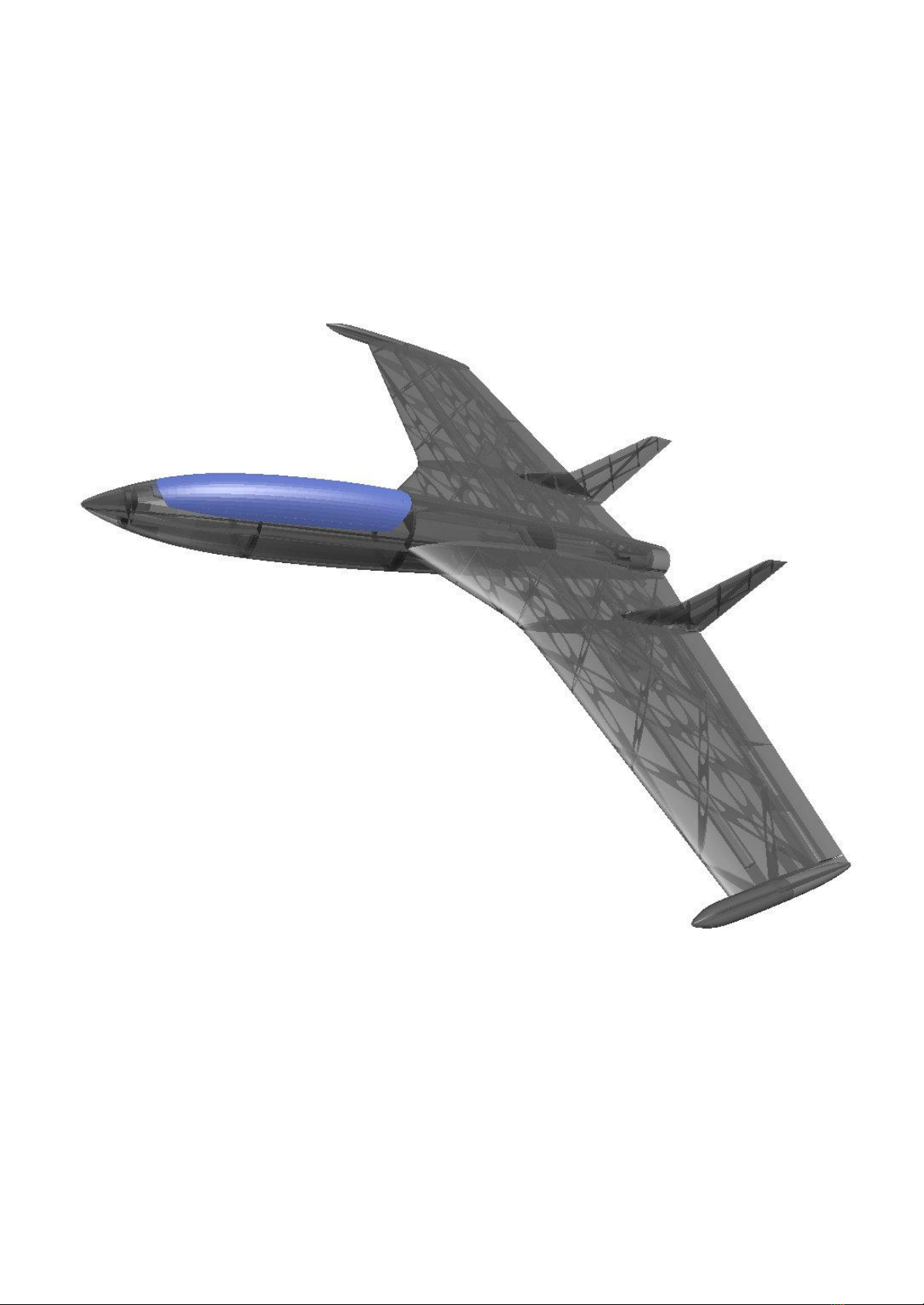
This custom design of a high speed futuristic fighter is designed for quick and easy
construction printed in PLA. For best results the canopy should be printed with clear PLA and
the motor mount and propeller assembly in regular PLA or PETG. Designed to suit the 2826
2200kv outrunner on a 5x5 propeller. Utilizing only elevons, this model performs high speed
and aerobatic flight extremely well. Links to components used can be found on the last page
of the user guide.
This model has taken many hours of hard work and testing in order to provide a nice flying
aircraft. Please do not share it. Please show your appreciation by directing interested parties
to the link below.
https://cults3d.com/en/3d-model/various/x-85-funjet
GENERAL SPECIFICATIONS
WINGSPAN: 800mm
PRINT TIME: 66 hrs
PRINT COST: $10 USD
PRINT WEIGHT: 620g
FLYING WEIGHT: 950g (1150g on 4s with LED’s)
ELECTRICS
MOTOR: 2826 2200KV or (2836 2500kv high power)
ESC: 30amp (min) recommend 40amp
SERVOS: 9g MICRO
BATTERY: 2200mah 3s (or similar)
INCLUDED:
STL FILES OF ALL COMPONENTS (scale to 1000% if not using S3D)
FACTORY FILES FOR (S3D) SIMPLIFY 3D FOR PRINTERS: 200x200200
300x300x400

BUILD OPTIONS:
This model has been designed to suit four different build configurations with the potential to increase
in the future thanks to its “screw together” design.
Standard - Using the proven external servo and control horn, this option is perfect for the “first time
builders” and those who want to get in the air fast.
RDS - Rotating drive system is an internally mounted arm which rotates the control surface through a
torque rod extending into the control surface. This results in no external control horns and reduces
drag and has a very clean appearance. The assembly procedure is only slightly more difficult than the
traditional methods.
LED - The option to install COB LED strips into the wings, fuselage, and vertical stabilizers as well as
5mm led’s into the wingtips and exhaust cone. This option adds a flare of class to the model and
gives the user a night flying weapon. It is suggested to run this version on 4s however it is possible to
run on 3s (not advised for flying at night).


REQUIRED TOOLS:
KNIFE
LIGHTER
SANDPAPER (MEDIUM GRIT 320
recommended)
PLIERS
CA GLUE
SCREW DRIVERS
FILE OR RASP
SOLDERING IRON (led version)
DRILL
REQUIRED COMPONENTS:
X1 2826 2200KV MOTOR (or similar)
X1 30AMP ESC
X1 2200MAH 3S or 4S(led version) LIPO OR SIMILAR
X2 9G SERVO
3mm BAMBOO FOOD SKEWERS
X2 10mm X 10mm X 2mm MAGNET (ROUND)
X4 16mm x 29mm HINGES
X1 10mm x 800mm or 500mm carbon tube or pine rod (OPTIONAL)
M2 x10mm screws
1mm piano wire
M2 push rod (110mm min length) < FOR RDS ONLY
VELCRO
LED VERSION:
4 meters COB 8mm LED STRIP
X4 5mm Red led
X1 5mm green led
X2 5mm white led
X1 adjustable dc-dc Voltage regulator
3 meters 2 core wire
Voltage regulator

ASSEMBLY INSTRUCTIONS
This model offers the option to add COB led strips for night flying. The following instructions
will have steps for assembly WITH and WITHOUT the LED strips. Steps for assembly using
the LED strips will be prefixed with a letter next to the step number, eg- “1a”
1
All faces which are to be glued to other parts need to be given a light sanding (scuff the
surface) to assist with glue adhesion.
2
Cut 10mm sections of skewer and place into alignment holes in the fuselage sections.
NOTE - It may be required to open up the holes a small amount if the fit is too tight. Do this
by using a 3mm drill bit. Gently spin it in reverse as you insert it into the hole. This will ensure
the bit does not tear the print.
Test fit the sections of the fuse before gluing to ensure a clean fit.

FUSELAGE ASSEMBLY
3a
- Cut x1 300mm (top of fuse) and x2 580cm (fuse belly) lengths of LED strip and test fit
them in the fuselage sections. NOTE- Led strips should face out for greatest effect.
- A small hole will need to be drilled or melted into the aft section of the wire tunnel of
Fuse 3 for the wires of the led strip to access the battery.
- Install the three red LED lights to the rear of fuse 5. NOTE - Led’s need to be installed
into the black mount fitting which come with the led’s for them to fit correctly.

- Solder the led strips and led’s so that their wires extend to roughly where the battery
will be fitted during flight. (power wires marked in red)
- Once the fitment looks satisfactory, glue all sections of the fuselage together using CA
3
Glue sections of the fuselage together using CA glue. (see images)

4 VERTICAL STABILIZERS
Glue the sections vertical stabilizers together.
NOTE: be sure to match up the side correctly. (example of left vertical stabilizer below)

4a
- Cut two 70mm lengths of LED strip and solder a 30mm length of power wire to one
end.
- Install the led strips into the front section of the vertical stabilizer with the led strip
facing outward. The power chord needs to be accessible from the opening as it will be
soldered to the wing later on.
WING ASSEMBLY
5a
- Test fit the sections of the wing together.
- Cut two 380mm (front slot), two 350mm (middle slot) and two 250mm (rear slot)
lengths of led strip to be fitted into the wings.

- Install the led strips into the outer sections of the wings and solder power wires for the
front and rear strips to the middle strip with power cables. (marked in red)
- Solder another power wire at the wing root end of the middle led strip which will reach
the battery section of the fuselage. (pos “+” to pos “+” and neg”-” to neg ”-”)
- The power cable for the led strip needs to feed through the servo wire tunnel in the
wing near the root of the inner wing section. Melt away a small section around the
middle led slot at the root and trip the slot back slightly to give the power wire room
when the wing is fitted to the fuselage.
- Melt or drill a small hole in the aft face of the servo wire tunnel and feed the wire
through it so the wire can be fed through the fuselage when the wings are fitted.

5
Cut two 35mm sections and one 25mm section of food skewer. Insert the 35mm sections in
the front two holes and the 25mm section into the aft holes of the vertical stabilizer.
Fit the vertical stabilizer to the Inner section of the wing using the skewers to align the parts.
The completion of this section should have the front two skewers protruding from the vertical
stabilizer which will assist the fitment of the outer wing. The aft skewer should be slightly
recessed so as not to interfere with the aileron travel.

6a
Solder the vertical stabilizer led strip to the outer wing (rear slot) led strip and test the led’s
before gluing the wing together.
6
Fit and glue the outer section of the wing to the already assembled inner section and vertical
stabilizer. The carbon or pine main spar should be test fit before gluing.

7aWINGTIPS
- Install a white led into the front of the wingtips and a red(left) and green(right) led into
the side of the front wingtips. The power wires should come out through the hole
behind the nav light mount.
- Connect the two led’s and add a length of power cable long enough to go through the
middle led strip in the wing section to the wing root, through the servo wire tunnel at
the wing root and into the fuselage up to the battery bay.

7
- Glue the sections of the wingtips together. NOTE- the trailing edge of each wing has
built in “up trim” so make sure the front to match the front and back sections correctly.
- Be sure to match up the correct wingtip with each wing.
8.1 Installing the Servo’s (standard version)
- Screw the servos to the servo covers and feed the servo wires through the wing into
the fuselage.
- Screw the servo covers into the wing with m2 screws.

8.2 Installing the Servo’s (RDS option)
- Using the screws provided with the servo, install the servo mounts to the servo mount
arms.
- Cut two 110mm lengths of 2mm push rod and bend according to the images below.
TOP VIEW
Left side Right side
SIDE VIEW
ISOMETRIC VIEW

- Fit the torque link to the end of the push rod with the short 90 deg bend.
- Fit the servo connector to the servo using small m1.6 or m2 screws. (be sure the
connector is centered in the neutral position when the servo has power.

- Insert the torque link and rod through the aileron end of the torque link tube and
secure it to the servo.
- Install the servo into the wing, the servo gear needs to be on the same side as the
tube for the torque link (see below). Note- The mount plates in the wing for the servo
consist of 4 layers and are quite thick. Pre-drilling with a 1.5mm drill bit is advised
before mounting with m2 screws.
- Assemble the connector and the torque link using a small screw. NOTE - The torque
link needs to be fitted to the connector so that the screw holds the push rod in the
torque link. See image. (fitting it the other way will allow the rod to fall out of the torque
link)
RDS INSTALLED

9 Installing the Ailerons
Glue the aileron sections together. Insert the hinges into the aileron first and test fit the
aileron to the wing.
NOTE: The hinge length may need to be trimmed slightly if the aileron does not seat all the
way into the hinge slot.
IMPORTANT! Only 2 drops of CA is needed for each slot for the hinges. Too much CA and
the hinge will bind and be unusable.
TIP: After adding the CA, use a tissue to wipe away the excess.
10
Mount the wingtips to the wings using two m2 screws per wing.
11
Install the wings to the fuselage using four m2 screws per wing.
12
Glue the sections of the canopy together.
13
Glue the magnets into the canopy and fuselage.

14 Wiring of the LED’s
The LED’s operate on 5v and can be plugged directly into a spare channel on the receiver.
The COB led strips run on 12v but it was found that Voltage sag during flight can cause the
led strips to dim. To remedy this, we advise running the model on 4s and using a voltage
regulator for night flights so that the LED strips stay bright throughout the flight.
Wire the voltage regulator between the battery and the LED strips tune it for and output of 12
volts.
Table of contents
Other 3D AEROWORKS Toy manuals

3D AEROWORKS
3D AEROWORKS Focke Wulf FW190-D9 Guide

3D AEROWORKS
3D AEROWORKS FUN JET X-88 Guide

3D AEROWORKS
3D AEROWORKS Pilatus PC-21 Guide

3D AEROWORKS
3D AEROWORKS Piper Turbo Arrow IV Guide

3D AEROWORKS
3D AEROWORKS PR1 Guide

3D AEROWORKS
3D AEROWORKS Yakovlev Yak-3 Guide

3D AEROWORKS
3D AEROWORKS PR1 Guide

3D AEROWORKS
3D AEROWORKS Extra 500 Guide
Popular Toy manuals by other brands

H-KING
H-KING Hellcat Little Nugget instruction manual

KidKraft
KidKraft Georgia Peach Dollhouse Assembly instructions

Black Horse Model
Black Horse Model Fieseler Fi156C STORCH instruction manual

Mega Bloks
Mega Bloks Spider-Man 1949 instruction manual

Brown Dog Gadgets
Brown Dog Gadgets Conductive Bracelet quick start guide

Gyros
Gyros S301G Using instruction