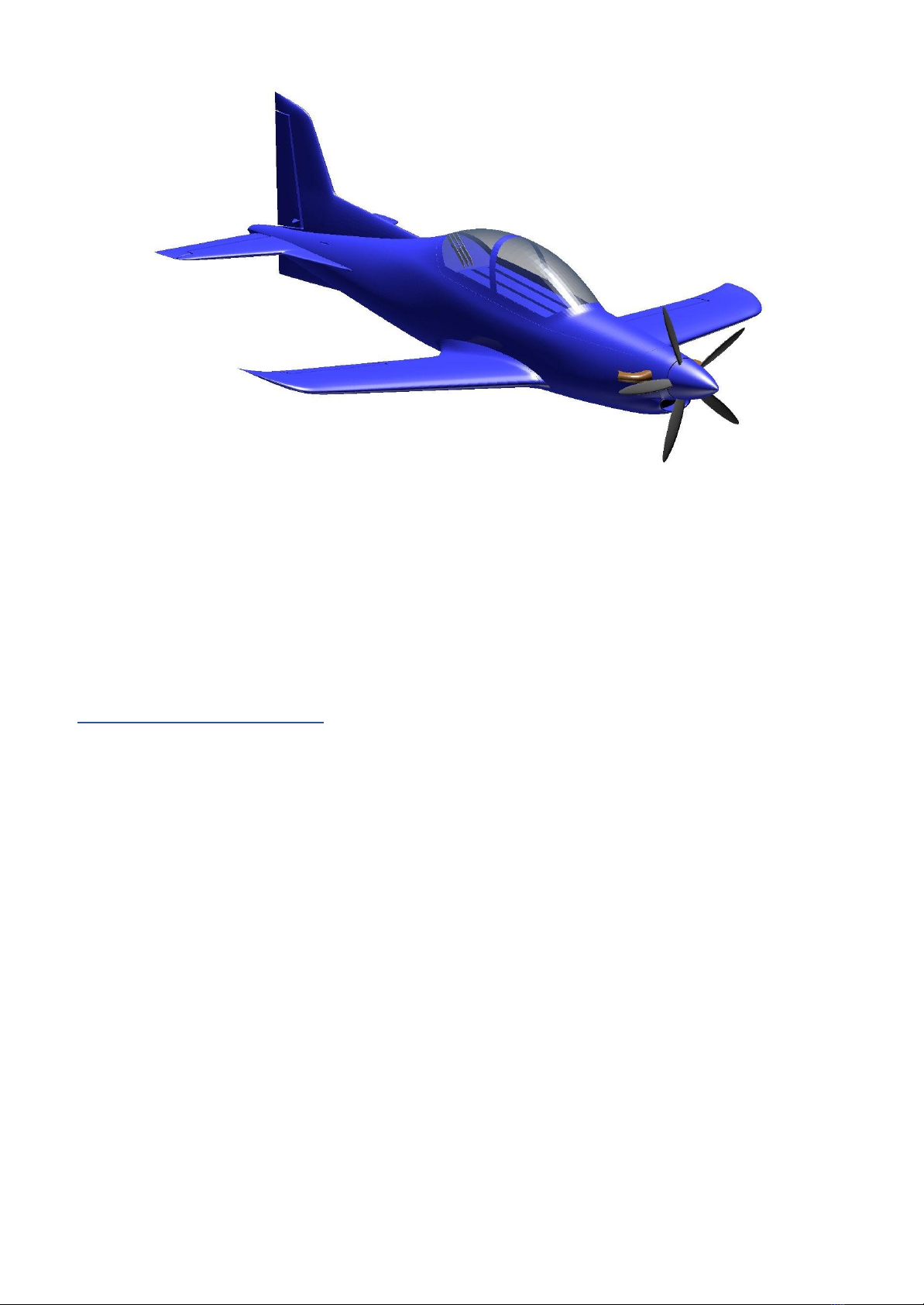
3D AEROWORKS Pilatus PC-21 Guide

ASSEMBLY MANUAL
AND USER GUIDE
Pilatus PC-21
By 3D AEROWORKS

OVERVIEW:
This replica of the Pilatus PC-21 is designed for quick and easy construction and printed
using light-weight PLA (LW-PLA). For best results the canopy should be printed with clear
PLA, and the motor mount and propeller assembly in regular PLA or PETG. A semi scale
propeller and hub is included in the plans designed to suit the 2804 2300kv outrunner (7x5)
in 2 blade configuration. Utilising full 4 channel controls; aileron, elevator, rudder and throttle,
this model performs extremely well given its small size and lightweight. Links to components
used can be found on the last page of the user guide.
This model has taken many hours of hard work and testing in order to provide a nice flying
aircraft. Please do not share it. Please show your appreciation by directing interested parties
to the link below.
https://cults3d.com/en/3d-model/various/pilatus-pc-21-600mm
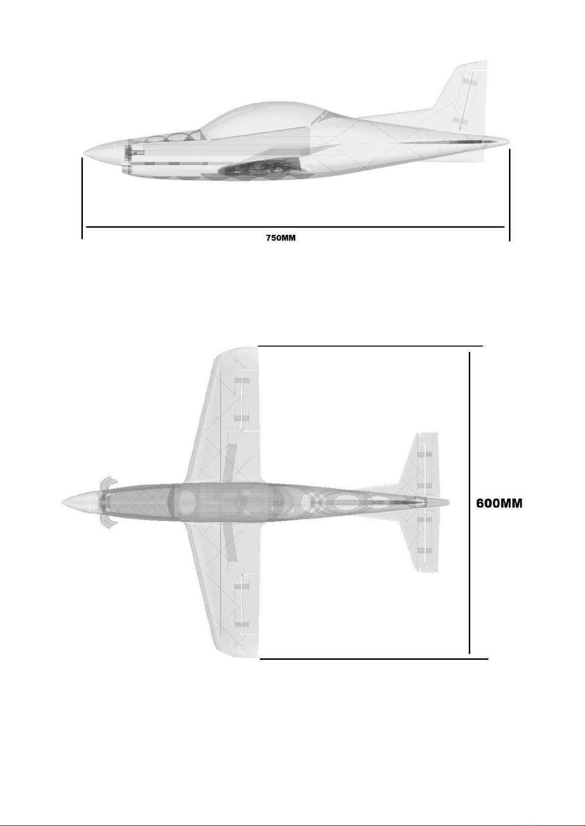
GENERAL SPECIFICATIONS
WINGSPAN: 600mm
PRINT WEIGHT: 205g
FLYING WEIGHT: 340g
ELECTRICS
MOTOR: 2804 2300KV
ESC: 10amp (min) 20amp (recommended)
SERVOS: 3.7g MICRO
BATTERY: 950MAH 2S (or similar)
INCLUDED
STL FILES OF ALL COMPONENTS
FACTORY FILES FOR SIMPLIFY 3D FOR PRINTERS: 200X200X200


REQUIRED TOOLS:
KNIFE
LIGHTER
SANDPAPER (MEDIUM GRIT)
PLIERS
CA GLUE
SCREW DRIVERS
FILE OR RASP
REQUIRED COMPONENTS:
X1 2804 2300KV MOTOR (or similar)
X1 12AMP or 20AMP ESC
X1 950MAH 2S LIPO OR SIMILAR
X4 3.7G MICRO SERVO
BAMBOO SKEWERS 3MM
HEAT SHRINK TUBE 3mm
X2 10mm X 10mm X 2mm MAGNET (ROUND)
X10 MICRO HINGES (OPTIONAL)
VELCRO
X2 x 200mm CARBON STRIP 3mm x 0.6mm (OPTIONAL)
M2 x10mm SCREWS
1mm PIANO WIRE
M2 PUSH ROD (200mm MINIMUM LENGTH)
** This model comes with the option for fixed style landing gear. The wings and fuselage
sections have alternate parts which accommodate 2mm struts for the main gear and 1mm
wire for the tailwheel. It is advised that the geared option only be used for tarmac or concrete
surfaces. Grass runways should be avoided when using the fixed gear.

ASSEMBLY INSTRUCTIONS
1
After all parts have been printed, some may require to be cleaned as LW-PLA is prone to
stringing. Do this by gently sanding back the rough sections with a file, sandpaper or blade
until the surface is smooth.
2
All faces which are to be glued to other parts need to be given a light sanding (scuff the
surface) to assist with glue adhesion.

3
Cut 15mm sections of skewer and place into alignment holes in the fuselage sections.
NOTE - It may be required to open up the holes a small amount if the fit is too tight. Do this
by using a 3mm drill bit. Gently spin it in reverse as you insert it into the hole. This will ensure
the bit does not tear the print.
Test fit the sections of the fuse before gluing to ensure a clean fit.
4
Glue all sections of the fuse together except fuse 1. This will be glued on last in order to
allow for cg balancing.
5
Once glued, with a sharp knife, remove the false floor of the battery hatch. (see pic/
highlighted faces) NOTE: The removed sections of LW-PLA that is the false floor will be
used as hinge pieces later. Do not throw away.

6
From part “fuse 3” remove the inner section of the lead tunnel with a knife or heated metal
rod to allow the servo lead for the aileron to pass through. (refer image)
7
Test fit the hinges in the hinge slots for each control surface and its parent part, this will make
gluing the control surface easier when the time comes. NOTE- Do not force the hinge if it is
too tight. Loosen the slot by gently inserting a stanley knife.
Using the LW-PLA as a hinge:
From the off-cuts from the fuselage false floor, cut small sections of 15mm x 7mm with the
7mm side being against the grain of the layers. Test fit the pieces into the hinge slots of the
control surface and stabiliser or wing.

8
Place a drop of CA in the hinge slot of the control surface and insert the hinge. Be sure that
the hinge is perpendicular to the control surface. Then bend the hinges to 90deg back and
forward a few times to make sure they are appropriately loose. (the outer aileron and
elevator hinge may need to be trimmed). See below
9
Fit the horizontal stabilisers to the fuselage using small sections of 3mm bbq skewers to align
the stabilises and glue with CA.

10
Bend a section of 1mm steel wire to connect the elevators together.
Test fit the wire and the elevators connection to the horizontal stabilisers before gluing the
wire to the elevators, or the elevators to the tail plane. There should be un-obstructed travel.
11
Glue the rudder, elevators and ailerons in place. Make sure each control surface has full and
free movement.
12
Glue the wingtips and tail cone in place (if required).

13
Cut four 15mm sections (2 per wing) of skewer. Insert the 15mm sections into the wings.
These will assist in aligning the wings when joining to the fuselage.
Glue the wings to the fuselage NOTE – if using 3mm x 0.6mm carbon strip, now is the time
to install it. Simply slide the carbon strip into the slot and cut it so it does not protrude out of
the wing (circled in red, see image). The cross structure of the fuselage spreads the load of
the wings at the root which negates the need of a connecting spar in the fuselage.
14
Run a string through the aileron servo wire tube from the mount hole for the aileron servo to
the wing root. Leave enough length so that you will be able to feed the string through the
fuse later.
15
Install all servos using a small amount of hot glue to secure it in place. The aileron servos
mounting tabs will need to be trimmed. Connect the ailerons to the servos using 1mm wire
and the printed linkage locks.

16
Using an appropriate length of skewer with 1mm steel wire on each end covered in heat
shrink tubing, connect the elevator and rudder to their relative servo.
Elevator = left side
Rudder = right side
17
Install the magnets to both the fuselage and the canopy using CA.

18
Install the desired motor mount to the fuselage using m2 screws. The mount holes may need
to be pre-drilled with a 2mm drill bit.
19
Wire up the ESC to the motor. The esc is intended to sit below the battery floor with the wires
connecting to the battery through the hole in the mid section of the fuselage floor.

20
Install the motor to the motor mount. The motor mount holes may need to be pre-drilled with
a 3mm drill bit.
21
Fit the propeller hub to the motor and screw in the blades using m2 x 10mm screws. Then
secure the spinner to the hub. The propeller blades will need to be pre-drilled with a 2mm
drill bit for ease of fitment.
Installing the propeller:
- Install the blade to the hub and secure it with an m2 x 10mm screw. (screw direction
towards the back of the hub)
- Install the hub to the motor.
- Secure with either metal nut provided or printed nut.
- Install the spinner. The spinner is designed with an m5 thread to suit most small
motors with a regular cw thread.

22 BALANCING AND CG
The ballast lead required should be placed in the hollow section of fuse 1. NOTE! Balancing
needs to be done with the propeller attached. See below
Fit the battery using Velcro as required and balance the aircraft inverted on the CG marking
points located 60mm aft of the leading edge at the wing root.
Once balanced appropriately, glue Fuse 1in place with ca.

RANGE OF TRAVEL:
NORMAL FLIGHT:
Elevator +/- 10mm
Rudder +/- 10mm
Aileron +/- 8mm
AEROBATIC:
Elevator +/- 15mm
Rudder +/- 25mm
Aileron +/- 15mm
LAUNCHING:
It was found that the safest and most successful launch technique for this model was the
under-arm style. The aircraft should be launched at approximately 20deg nose up at 50% to
75% power. Too steep and the aircraft will stall, too shallow and it will contact the ground.

PARTS LINKS:
X1 2804 2300KV MOTOR
https://de.aliexpress.com/item/32880887286.html?spm=a2g0o.productlist.0.0.138a29f3Y7bX
F4&algo_pvid=95040ddc-7eca-4d17-b061-ba5ed52d7eac&algo_exp_id=95040ddc-7eca-4d1
7-b061-ba5ed52d7eac-3
X1 20AMP ESC
https://www.aliexpress.com/item/32905632543.html?spm=a2g0o.productlist.0.0.293536aecw
u7yT&algo_pvid=09b70550-d77e-46d3-b25e-621167aaeef6&algo_expid=09b70550-d77e-46
d3-b25e-621167aaeef6-0&btsid=0b0a556616077433274567589e7b03&ws_ab_test=search
web0_0,searchweb201602_,searchweb201603_
X1 950MAH 2S LIPO OR SIMILAR
https://www.aliexpress.com/item/32907577121.html?spm=a2g0s.9042311.0.0.30714c4dJd4d
ZG
X4 3.7G MICRO SERVO
https://www.aliexpress.com/item/32965734270.html?spm=a2g0o.productlist.0.0.57d95e97a
WNNAJ&algo_pvid=4824ea1c-06ed-43e8-b6c7-9737d1226dbe&algo_expid=4824ea1c-06ed
-43e8-b6c7-9737d1226dbe-0&btsid=0bb0623415991458444523660eb7bd&ws_ab_test=sea
rchweb0_0,searchweb201602_,searchweb201603_
X2 BAMBOO FOOD SKEWERS (3mm diameter)
HEAT SHRINK TUBE 3mm
https://hobbyking.com/en_us/turnigy-3mm-heat-shrink-tube-black-1mtr-1.html?queryID=c16c
094bb26b18e39fabcb12a93a96cb&objectID=46911&indexName=hbk_live_magento_en_us_
products

X4 10mm X 10mm X 2mm MAGNET (ROUND)
https://www.aliexpress.com/item/1005001362617359.html?spm=a2g0o.productlist.0.0.5da36
07dAATh5j&algo_pvid=b9e32b8a-0d4f-469a-b838-b478442dda50&algo_expid=b9e32b8a-0
d4f-469a-b838-b478442dda50-0&btsid=0bb0623a15991797178681785e1811&ws_ab_test=s
earchweb0_0,searchweb201602_,searchweb201603_
X10 MICRO HINGES
https://hobbyking.com/en_us/super-light-pivot-round-hinges-d2xw8xl24mm-12pcs.html
VELCRO – (local hardware store)
X2 x 200mm carbon strip 3mm x 0.6mm (optional)
https://www.aliexpress.com/item/32576381076.html?spm=a2g0o.productlist.0.0.4e922cc3nR
6757&algo_pvid=500714e5-ce74-4e52-a1b0-e349cac3f595&algo_expid=500714e5-ce74-4e
52-a1b0-e349cac3f595-7&btsid=0bb0623e15991463277515177efc08&ws_ab_test=searchw
eb0_0,searchweb201602_,searchweb201603_
m2 x10mm screws
https://www.ebay.com.au/itm/400PCS-M2-M2-6-Pan-Head-Self-Tapping-Screws-Assorted-Kit
-Stainless-Steel-Black/254399626404?hash=item3b3b663ca4:g:CLEAAOSwQLZdsqkd&frce
ctupt=true

Thank you for supporting us! We hope you enjoy many
hours of flying your micro PC-21. If you have any
questions regarding the build process or set-up of your
model, please contact us at:
Other 3D AEROWORKS Toy manuals

3D AEROWORKS
3D AEROWORKS Yakovlev Yak-3 Guide

3D AEROWORKS
3D AEROWORKS Focke Wulf FW190-D9 Guide

3D AEROWORKS
3D AEROWORKS Piper Turbo Arrow IV Guide

3D AEROWORKS
3D AEROWORKS PR1 Guide

3D AEROWORKS
3D AEROWORKS PR1 Guide

3D AEROWORKS
3D AEROWORKS FUN JET X-88 Guide

3D AEROWORKS
3D AEROWORKS Extra 500 Guide

3D AEROWORKS
3D AEROWORKS X-88 Fun-Jet Guide
Popular Toy manuals by other brands

ThinkGizmos
ThinkGizmos TG935 SPEED MASTER QUAD BIKE V2 user manual

Stevens Aero Model
Stevens Aero Model Build It! Baby Ace Build instructions

V-tech
V-tech Touch & Explore Activity Table 5408 Information manual

LaserPegs
LaserPegs NG100 instructions

Spinmaster
Spinmaster Peek-A-Roo instruction sheet

V-tech
V-tech Toot-Toot Drivers Big Vehicle Carrier Parents' guide