3M 4604GW User manual

Instructions
January 1999
34-7046-2402-1-A
Reenterable Gel Wrap PST
Dome Closure
Obsolete
Document

2
Obsolete
Document

3
Contents:
1.0 General ...........................................................................................................................................................4
2.0 Kit Contents....................................................................................................................................................4
3.0 PST Closure Capacity ....................................................................................................................................5
4.0 Cable Preparation ........................................................................................................................................... 5
5.0 Bonding and Grounding.................................................................................................................................6
6.0 Splicing...........................................................................................................................................................6
7.0 Sealing Collar Installation - 4604GW and 4606GW.....................................................................................7
8.0 Gel Wrap Installation - 4604GW and 4606GW ............................................................................................8
9.0 Closure Installation - 4604GW and 4606GW ...............................................................................................9
10.0 Sealing Collar Installation - 4608GW and 4608XL-GW ..............................................................................11
11.0 Gel Wrap Installation - 4608GW and 4608XL-GW......................................................................................12
12.0 Closure Installation - 4608GW and 4608XL-GW.........................................................................................13
13.0 Closure Reentry..............................................................................................................................................14
14.0 Retrofit on Gel Wrap PST Dome Closure .....................................................................................................15
Obsolete
Document

4
2.1 Additional Materials Required
• Vinyl Tape
• Shield Bond Connectors
• Splice Connectors
• Elastic Vinyl Film
• Grounding Wires
Note: All components must be installed per instructions to be effective.
4608GW and 4608XL-GW Closures
Closure Assembly (A)
Dome
Base
O-ring
Latch
Gel End Seal Core (B)
Gel Sealant Strip (C)
Gel Wrap (D)
PST (E)
Sheath Scuff (F)
4604GW and 4606GW Closures
Closure Assembly (A)
Dome
Base
O-ring
Latch
Gel End Seal Core (B)
Gel Sealing Strip (C)
Gel Wrap (D)
PST (E)
Sheath Scuff (F)
1.0 General
The 3M™Reenterable Gel Wrap PST Dome Closure is used for new and existing above-ground splices contained
within a pedestal or below-ground splices within a hand-hole.
2.0 Kit Contents
(C)
(F)
(C)
(D)
(E)
(A)
(B)
(E)
(F)
(A) (D)
(B)
Obsolete
Document

5
(W x D)
(H)
Closure
Outside Dim. 22.5"
(572 mm)
-
Closure
Height
Approx. Bundle
Diameter
Minimum Reliable
CAD Pedestal
Main
Cables
Terminal
Cables
Branch
Cables
Drop
Cables
*Approx.
Splice Range
2.5"
(64 mm) 3.9"
(99 mm)
0.4" - 0.6"
(10 - 15 mm) 0.4" - 0.6"
(10 - 15 mm)
0.7" -1.0"
(18 - 25 mm)
100 pr. - MS2
50 pr. - UR 300 pr. - MS2
100 pr. - UR
4604GW 4606GW 4608GW 4608XL-GW
3.8" x 2.8"
(97 x 71 mm) 5.6" x 3.9"
(142 x 99 mm)
0.35" max
(9 mm) max
2 max
0.35" max
(9 mm) max
2 max
0.35" max
(9 mm) max
2 max
0.35" max
(9 mm) max
2 max
7.0" x 5.4"
(178 x 137 mm) 7.0" x 5.4"
(178 x 137 mm)
22.5"
(572 mm) 23.5"
(597 mm) 33.5"
(851 mm)
5.3"
(135 mm) 5.3"
(135 mm)
46 8 12/70
0.5" - 1.1"
(13 - 28 mm) 0.9" - 1.6"
(23 - 41mm) 1.4" - 2.5"
(36 - 64 mm) 1.4" - 2.5"
(36 - 64 mm)
0.4" - 0.8"
(10 - 20 mm) 0.4" - 0.8"
(10 - 20 mm)
0.9" - 1.3"
(23 - 33 mm) 0.9" - 1.3"
(23 - 33 mm)
600 pr. - MS2
300 pr. - UR 900 pr. - MS2
400 pr. - UR
6"
(151 mm)
23"
(584 mm)
Scuff Both
Cables
Remove Sheath
Preparation A Preparation B
6"
(151 mm)
15"
(381 mm)
Scuff Both
Cables
Remove Sheath
W D
H
3.0 PST Closure Capacity
*Note: Based on two bank 4000-DWP and ScotchlokTM connectors installed per 3M practices.
Examples: 100 pair means 100 pair In and 100 pair Out or 100 pair straight splice.
3.1 Overall closure dimensions (See PST Closure Capacity Chart).
4.1 Remove sheath and scuff both
cables as noted for the following
closure sizes.
Preparation A: 4604GW, 4606GW, 4608GW
Preparation B: 4608XL-GW
4.0 Cable Preparation
Obsolete
Document

6
5.2 Install external ground wires to bonding connector studs and
run along the cables.
Note: For external grounding of sealed copper plant, a solid
copper wire bond must be used. For internal bonding/
grounding, a stranded, braided or any combination of
bonding/grounding wire may be utilized.
5.0 Bonding and Grounding
5.1 Install bonding connectors per system practice. Bonds should
be placed so that the studs of the connectors are facing forward.
5.3 Insulate bonding connectors by wrapping with vinyl tape.
6.0 Splicing
6.1 Splice per company practice.
6.2 Splice in tail of a terminal block when required.
Obsolete
Document

7
7.0 Sealing Collar Installation – 4604GW and 4606GW
7.1 Cut and remove packaging from gel end seal core.
7.2 Slit gel end seal ports along the length of plugs for desired number of
cables to be installed and remove plugs.
Use plugs 1 and 2 for main cables and plug 3 for branch or terminal
cable.
Note: A fourth plug is available for the 4606GW closure.
7.3 Install gel end seal core 2" (51 mm) below the sheath opening. Pull lips
of seal, created by cutting and removing plug, around cables. Remove
packaging from gel sealing strip. Wrap the gel sealing strip around the
core and ground wires with a slight tension.
Note: Place ground wires and drop wires between layers in gel sealing
strip. Ensure wires have one layer of gel between them and cable
sheath. There should be at least 0.25" (6 mm) between wires.
7.4 Squeeze gel end seal to insure a seal between layers and cables.
Note: Closure assembly must rest on end seal when placed over the splice.
Move end seal upward, if necessary.
1
3
2
lips
Obsolete
Document

8
8.3 Trim off excess gel wrap if needed. Make sure that the top of the
bundle is fully covered prior to trimming gel wrap.
8.4 Starting 2" (51 mm) below the gel end seal, begin tightly wrapping
the elastic vinyl film. Continue tightly wrapping the elastic vinyl
film over the length of the gel wrap and bundle. Make certain that
the top of the gel wrap is tightly covered by the elastic vinyl film.
Wrap three highly stretched layers of elastic vinyl film. Secure the
end of the elastic vinyl film with vinyl tape.
7.5 Pull cables together with tape or cable ties to ensure proper fit to
closure.
8.0 Gel Wrap Installation – 4604GW and 4606GW
8.1 Starting at bonding connectors, begin wrapping elastic vinyl film.
Continue wrapping the elastic vinyl film along the bundle until the
bundle is fully covered.
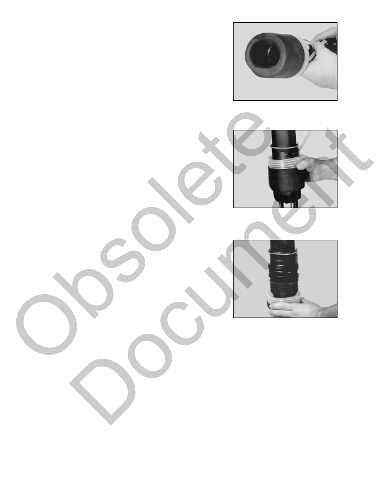
8.2 To install gel wrap, first remove the protective cover from one side.
Place the gel wrap behind the cables (the unprotected side should
face the bundle); position it so that the lower edge is near the bottom
of the end seal. Anywhere between the bottom and middle of the
end seal is acceptable. At this time remove the remaining protective
cover from gel wrap.
Wrap the gel wrap around the end seal so that the ends overlap and
press them firmly together. Continue wrapping the gel wrap along
the bundle, assuring that the ends overlap, until the bundle is fully
sealed.
Obsolete
Document

9
9.0 Closure Installation – 4604GW and 4606GW
9.1 Remove cardboard insert and pull core tail through the center of PST
until core is even with PST edge.
9.2 Slide PST over closure so that PST tail is pointed toward the top of
the closure. The core tail MUST be unwound upward. Position PST
bottom edge between the bottom of the wire form latch and the base's
top rib.
Note: Optional method is to put closure over the splice bundle and
position PST 2" (51 mm) below the gel end seal. While holding
the PST and closure with one hand, unwind the core by pulling
on the core tail with the other hand in an upward and outward
COUNTERCLOCKWISE direction.
9.3 While holding the PST and closure with one hand, unwind the core by
pulling on the core tail with the other hand in an upward and outward
COUNTERCLOCKWISE direction until approximately 0.5"(13 mm)
of the PST is shrunk onto the closure.
9.4 Push PST towards bottom of closure. This will invert the PST.
Note: Do not force the PST to slide on the closure during inversion.
Obsolete
Document

10
9.5 Pull the core material from the PST until the PST is even with
the bottom of the closure.
9.6 Place assembly over splice and onto gel end seal. Insure the
wireform latch and the 3M logo are facing forward.
9.7 Continuously push PST downward while pulling the rest of the core
material.
9.8 When the PST is in place, remove the core wrap from around the
cable.
9.9 For pedestal closure applications, secure the closure to pedestal,
mount terminal block and connect ground wires according to system
practice.
Obsolete
Document

11
10.5 Wrap the gel sealant strip around the core and ground wires with a
slight tension.
Note: Place ground wires and drop wires between layers in gel.
Insure wires have one layer of gel between them and cable
sheath. There should be at least 0.25" (6 mm) between wires.
10.4 Remove packaging from gel sealant strip.
10.3 Install gel end seal core 2" (51 mm) below the sheath opening. Pull
lips of seal, created by cutting and removing plug, around cables.
1
2
3
10.2 Slit gel end seal ports along the length of plugs for desired number
of cables to be installed and remove plugs.
Use plugs 1 and 2 for main cables and plugs 3 and 4 for branch or
terminal cables.
10.1 Cut and remove packaging from gel end seal core.
10.0 Sealing Collar Installation – 4608GW and 4608XL-GW
Obsolete
Document

12
10.6 Squeeze gel end seal to insure a seal between layers and cables.
10.7 Pull cables together with tape or cable ties to ensure proper fit to
closure.
11.4 Starting 2" (51 mm) below the gel end seal, begin tightly wrapping
the elastic vinyl film. Continue tightly wrapping the elastic vinyl
film over the length of the gel wrap and bundle. Make certain that
the top of the gel wrap is tightly covered by the elastic vinyl film.
Wrap three highly stretched layers of elastic film. Secure the end of
the elastic vinyl film with vinyl tape.
11.3 Trim off excess gel wrap if needed. Make sure that the top of the
bundle is fully covered prior to trimming gel wrap.
11.0 Gel Wrap Installation – 4608GW and 4608XL-GW
11.1 Starting at bonding connectors, begin wrapping elastic vinyl film.
Continue wrapping the elastic vinyl film along the bundle until the
bundle is fully covered.
11.2 To install gel wrap, first remove the protective cover from one side.
Place the gel wrap behind the cables (the unprotected side should
face the bundle); position it so that the lower edge is near the bottom
of the end seal. Anywhere between the bottom and middle of the end
seal is acceptable. At this time remove the remaining protective
cover from gel wrap.
Wrap the gel wrap around the end seal so that the ends overlap and
press them firmly together. Continue wrapping the gel wrap along
the bundle, assuring that the ends overlap, until the bundle is fully
sealed.
Obsolete
Document

13
12.0 Closure Installation – 4608GW and 4608XL-GW
12.1 Remove cardboard insert and pull core tail through the center of PST
until core is even with PST edge.
12.4 Place assembly over splice and onto gel end seal. Insure the wireform
latch and the 3M logo are facing forward. Mate the plate with the base.
12.3 While holding the PST and closure with one hand, unwind the core by
pulling on the core tail with the other hand in an upward and outward
COUNTERCLOCKWISE direction until approximately 2.0" (51 mm)
of the PST is shrunk onto the closure.
12.2 Slide PST over closure so that the PST tail is pointed toward the top of
the closure. The core tail MUST be unwound upward. Position PST
bottom edge within 0.5" (13 mm) of the bottom of the base.
Note: Optional method is to put closure over the splice bundle and
position PST 2" (51 mm) below the gel end seal. While holding the
PST and closure with one hand, unwind the core by pulling on the
core tail with the other hand in an upward and outward
COUNTERCLOCKWISE direction.
Obsolete
Document

14
12.5 Push PST towards bottom of closure. This will invert the PST.
12.6 Continuously push PST downward while pulling the rest of the core
material.
12.8 For pedestal closure applications, secure the closure to pedestal,
mount terminal block and connect ground wires according to system
practice.
12.7 When the PST is in place, remove the core wrap from around the
cable.
13.0 Closure Reentry
13.1 Reentry of closure is accomplished by pulling out and pushing down
the wireform latch. The latch will lift the dome of the closure from
the base as it is pulled.
13.2 Re-enter the splice bundle by cutting vertically through the layers of
elastic vinyl film and gel wrap and push the covering back to expose
the wire work. When you are finished with the wire work, reform
the gel wrap to its original position to cover the splice bundle.
13.3 Cut a 3 inch (7.6 cm) wide strip of gel wrap and use it to seal the
opening. Overlap the gel wrap strip equally on both sides of the
opening and squeeze it down to ensure a good seal.
13.4 Wrap the entire splice bundle with three tightly stretched half-lapped
layers of elastic vinyl film. Secure the ends of the splice bundle
with vinyl tape.
Obsolete
Document

15
13.5 To replace the closure dome, PLACE dome on to the base. Close the
wire form latch, insuring that it catches the protrusions on the dome.
Note: Wipe O-Ring clean if dirty and relubricate. Cable grease is
acceptable.
14.0 Retrofit on Gel Wrap PST Dome Closure
14.1 Existing 3M™Gel Wrap PST Closures can be
converted to reenterable closures by using the following
procedures.
Cut PST from top to bottom and pull it away from the closure
body and sealing collar.
14.2 Remove vinyl tape from butt of closure and slide closure off.
14.3 Slide the reenterable closure assembly over the splice, to check
fit of gel end seal.
14.4 If more than one wrap of gel is visible, trim the strip, and
rewrap. Repeat until only one wrap of gel is visible. If the gel
end seal is too small, a 4600GSS gel sealant strip may be
necessary to build the seal to the proper size.
14.5 Refer to steps 8.4 or 11.4. Follow procedures as directed.
14.6 Complete assembly as outlined in the installation procedures.
Obsolete
Document

16
Important Notice
All statements, technical information and recommendations related to the Seller's products are based on information believed to be
reliable, but the accuracy or completeness thereof is not guaranteed. Before utilizing the product, the user should determine the suitability
of the product for its intended use. The user assumes all risks and liability whatsoever in connection with such use.
Any statements or recommendations of the Seller which are not contained in the Seller's current publications shall have no force or effect
unless contained in an agreement signed by an authorized officer of the Seller. The statements contained herein are made in lieu of all
warranties, expressed or implied, including but not limited to the implied warranties of merchantability and fitness for a particular purpose
which warranties are hereby expressly disclaimed.
SELLER SHALL NOT BE LIABLE TO THE USER OR ANY OTHER PERSON UNDER ANY LEGAL THEORY, INCLUDING BUT NOT
LIMITED TO NEGLIGENCE OR STRICT LIABILITY, FOR ANY INJURY OR FOR ANY DIRECT, INDIRECT, INCIDENTAL OR
CONSEQUENTIAL DAMAGES SUSTAINED OR INCURRED BY REASON OF THE USE OF ANY OF THE SELLER'S PRODUCTS.
Recycled paper
50% pre-consumer
10% post-consumer
Telecom Systems Division
6801 River Place Blvd.
Austin, TX 78726-9000
800/426-8688
http://www.3M.com/telecom Litho in USA
© 3M 1999 34-7046-2402-1-A
Obsolete
Document
This manual suits for next models
3
Table of contents
Other 3M Cables And Connectors manuals
Popular Cables And Connectors manuals by other brands

TE Connectivity
TE Connectivity VAL-U-LOK 3-1586040-6 instruction sheet

Metra Electronics
Metra Electronics CS-1X2HDMSPL5 operating instructions

Appsys ProAudio
Appsys ProAudio ADS-8 user manual

SEI
SEI Lynx-CustomFit LYNX2-ST installation manual

Eaton
Eaton RMQ-Titan C22-PV Series Original operating instructions

LumX
LumX LM 84015 instruction manual