3M 5415A-IJ User manual

3M™ Cold Shrink Integrated Splice
Kit QS-III 5415A-IJ
for Jacketed Concentric Neutral (JCN) Cable
Instructions
IEEE Std. 404
15 kV Class
150 kV BIL
CAUTION
Working around energized systems may cause serious injury or death. Installation should
be performed by personnel familiar with good safety practice in handling electrical
equipment. De-energize and ground all electrical systems before installing product.
Kit Selection Table
Kit Number Cable Insulation O.D. Range Conductor Size Range
5415A-IJ 0.64" to 1.01"
(16,3 to 25,7 mm)
2 - 4/0 AWG*
(35–95 mm2)
* Splices (including size transitions) can be made to smaller or larger conductors (but larger conductors may require special neutral
handling), provided both cables are within the Insulation O.D. Range and the connector meets the dimensional requirements
shown below.
Connector Dimensional Requirements
Minimum Inches (mm) Maximum Inches (mm)
Outside Diameter 0.40" (10,2 mm) 1.10" (28 mm)
Length
Aluminum (Al/Cu) Compression —4.50" (114 mm)
Length
Copper Compression and 3M™ Shearbolt Connector
QCI 2-250
—5.00" (127 mm)
September 2010
78-8127-8867-3-B3

2 78-8127-8867-3-B
1.0 Kit Contents
a. 3M™ Cold Shrink Integrated Splice Body 5415A-IJ (1 ea.)
b. Constant Force Springs (4 ea.)
c. Red Compound Tubes (non-silicone grease) (2 ea.)
d. Scotch® Rubber Mastic Tape 2228 Rolls, 2" x 36" (2 ea.)
e. Scotch® Mastic Sealing Strips 2230, 6" length (8 ea.)
f. Cold Shrink Adapter Tube (2 ea.*)
g. 3M™ Cable Cleaning Pads CC-3 (1 ea.)
h. Scotch® Electrical Shielding Tape 24, 1" x 15' ( 1 ea.)
i. 3M™ Aluminum Foil Tape Strips 1115B, 10" length (2 ea.)
j. Cut-back Template (1 ea.)
k. Instruction Booklet (1 ea.)
*Cold shrink adapter tube may not be included in all kits.
Note: Do not use knives to open plastic bags.
Note: Connector not shown, but if included, it is indicated on the packaging label.

78-8127-8867-3-B 3
2.0 Prepare Cables
2.1 Check to be sure the cable fits within the kit ranges as shown on the cover page.
2.2 Prepare cables according to standard procedures. Refer to template provided or illustration below for proper
dimensions (Figure 1).
13 1/4"
(337 mm)
6 3/4"
(171 mm)
3 1/2"
(89 mm)
Insulation
Semi-Con
Neutral Wires
Cable Jacket
Figure 1
2.3 Carefully bend the cut neutral wires up and away from the cable semi-con as shown. Fold one Scotch® Mastic
Sealing Strip 2230 in half lengthwise and apply one wrap only at cable jacket edge under the neutral wires
(Figure 2).
Insulation
Semi-Con
Neutral Wires
Scotch® Mastic Sealing Strip 2230
Fold mastic strip in half lengthwise
Figure 2

4 78-8127-8867-3-B
2.4 Mark the cable semi-con 4" (102 mm) from the cable jacket edge. Apply two half-lapped layers of Scotch®
Electrical Shielding Tape 24 over the cable semi-con, starting from the mastic edge out to the mark on the
semi-con and back. Half-hitch to tie off (Figure 3).
Insulation
Semi-Con
Neutral Wires
Scotch® Mastic Sealing Strip 2230
4"
(102 mm)
Scotch® Electrical Shielding Tape 24
Figure 3
2.5 Carefully lay neutral wires back down on top of the shielding tape and press into mastic. Keep wire profile low
by following the concentric turn in the cable (Figure 4).
2.6 Remove the liner from one 3M™ Aluminum Foil Tape Strip 1115B and secure the ends of the neutral wires.
Wrap the aluminum tape on top of itself and tightly press down on the edge of the tape toward the end of the
electrical shielding tape (Figure 4).
Insulation
Semi-Con
Neutral Wires
3M™ Aluminum Foil Tape Strip 1115B
Scotch® Electrical Shielding Tape 24
Press down edge tightly
Figure 4

78-8127-8867-3-B 5
2.7 Apply a Scotch® Mastic Sealing Strip 2230 over the previously applied mastic strip and overlapping onto the
cable jacket. Knead mastic around neutral wires. Overwrap mastic with vinyl tape, taking care not to extend
tape along neutral wires (Figure 5).
Scotch® Mastic Sealing Strip 2230
Overwrap with vinyl tape
Cable Jacket
Figure 5
2.8 Clean or cover cable jacket 30" (760 mm) from jacket edge on side where splice body will be parked.
2.9 Slide integrated splice body onto clean cable jacket, loose core end first (Figure 6).
Loose core end
Integrated splice body
Cleaned cable jacket
Figure 6
3.0 Install Connector
Note: If using a crimp-type connector, go to step (3.3).
3.1 If using a 3M™ Shearbolt Connector QCI 2-250, refer to the instructions included with the connector for
insulation cut-back dimension. Insulation removal length shall not exceed 2 1/2" (64 mm) from conductor end
(Figure 7).
Refer to connector instructions for dimensions
Figure 7

6 78-8127-8867-3-B
3.2 Install 3M™ Shearbolt Connector QCI 2-250 according to the instructions included with the connector
(Figure 8).
Connector
Shearbolt
Figure 8
Go to section 4.0 “Install Splice.”
3.3 If using a crimp type connector, remove cable insulation for 1/2 connector length plus an allowance* for
increases in connector length due to crimping. Insulation removal length shall not exceed 2 1/2" (64 mm) from
conductor end. Do not install connector now (Figure 9).
*Note: This assumes that the installer has determined the increased length of an aluminum connector crimped
with a specific tool and die.
Aluminum (Al/Cu) Crimp Connector Growth Chart
Conductor Size Typical growth allowance (per end)
2 - 3/0 AWG 1/8" (3 mm)
4/0 AWG 1/4" (6 mm)
Note: 1) Copper connectors do not require a length change allowance.
2) Maximum aluminum connector crimped length allowed is 5.0" (127 mm).
One-half connector length
+ growth allowance*
Figure 9

78-8127-8867-3-B 7
3.4 For 2 through 1/0 AWG copper connectors, 2 and 1 AWG aluminum connectors, or connectors with an
O.D. between 0.40–0.55" (10,2–14,0 mm): Park the cold shrink adapter tube with the WHITE CORE on the
insulation.
For 2/0 through 4/0 AWG copper connectors or connectors with an O.D. between 0.50–0.64"
(12,7–16,3 mm): Park the cold shrink adapter tube with the RED CORE on the insulation. (Figure 10).
Cold shrink adapter tube
Figure 10
3.5 Install connector. See table (on cover) for proper connector dimensions. (For standard 3M™ Connectors, refer
to table at the end of this instruction for crimping infrmation). Remove any excess oxidation inhibitor from
connector ends if aluminum connector is used (Figure 11).
Connector
Figure 11
4.0 Install Splice
4.1 Apply a tape marker to semi-con insulation shield on cable which does not contain splice. Measure 8 1/2"
(216 mm) from center of connector (Figure 12).
Tape Marker
Semi-con
8 3/4"
(222 mm)
Figure 12
8 1/2"
(216 mm)

8 78-8127-8867-3-B
4.2 If using cold shrink adapter tube: Position adapter tube over the connector. Shrink adapter near center of
connector by pulling and unwinding the loose core end in a counter-clockwise direction (Figure 13).
Cold shrink adapter tube
Figure 13
4.3 Clean cables using standard practice:
a. Do not allow solvent or abrasive to contact the cable semi-conductive insulation shield.
b. Do not reduce cable insulation diameter below 0.64" (16,3 mm) specified for the splice.
c. The insulation surface must be round, smooth and free of cuts/voids. Sanding may be necessary, finish
sanding should be done with a 300 grit or higher electrical grade abrasive.
d. Make certain that the cable insulation is smooth, clean and dry before continuing.
4.4 Apply red compound on cable insulations, making certain to fill in edge of cable semi-con. Do not use
silicone grease (Figure 14).
Apply Red
Compound
Apply Red
Compound
Fill semi-con step Fill semi-con step
Figure 14

78-8127-8867-3-B 9
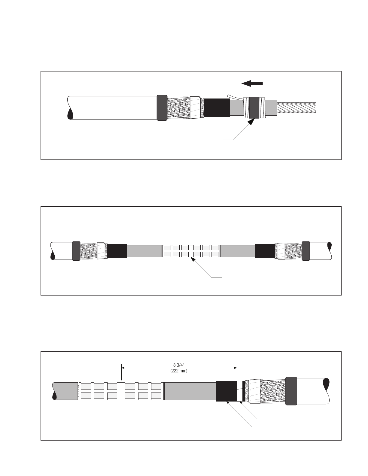
4.5 Position the splice body over connector area, aligning end of the splice body (not the core) at the center
of the tape marker. Slowly start to remove the splice core by pulling and unwinding the loose core end
counterclockwise, allowing only ¼" (6 mm) of the splice to shrink onto the tape marker. Carefully slide the
splice body off the tape marker by pulling and twisting until the entire tape marker is exposed. Continue
removing the core to complete the splice body installation (Figure 15).
Note: The splice body ends must overlap onto the semi-con of each cable by at least 1/2" (13 mm).
Note: Do not push the splice body toward the tape marker as this may cause the end to roll under. If the end
does roll under, DO NOT use sharp-edged tools to pull it out as this could cut and damage the splice.
Unwind Counter-clockwise
Align splice body with tape marker
Figure 15
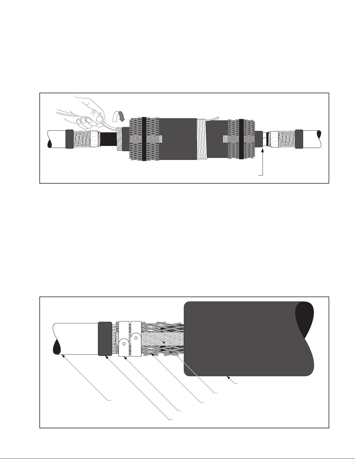
5.0 Connect Shielding
5.1 Remove the vinyl tape holding the shield sleeve on the rejacketing tube, and spread the shield sleeve out toward
the cable jacket.
Note: The 3M™ Cold Shrink Integrated Splice Body includes a pre-installed ground braid for external
grounding on either side of the splice body. If not using the ground braid, it may be tied into the ground
system with the shield sleeve using constant force springs as shown below.
5.2 Hand-tighten the shield sleeve outward and secure it (along with the ground braid if not grounding externally)
to the neutral wires on either side of the splice using two constant force springs on each end between the
vinly tape at the jacket edge and the aluminum foil tape as shown. Trim excess ground braid if needed. Cinch
(tighten) the spring after wrapping the final winding (Figure 16).
Ground Braid
Aluminum Foil Tape beneath Shield Sleeve
Constant Force Springs
Cable Jacket
Rejacketing Tube
Vinyl Tape
Figure 16

10 78-8127-8867-3-B
5.3 Wrap two half-lapped layers of vinyl tape over the constant force springs (Figure 17).
Vinyl Tape
Figure 17
6.0 External Grounding (Optional)
Note: Use these instructions if circuit grounding is required at this location.
6.1 Connect a ground wire to the pre-installed ground braid on the integrated splice using an appropriate connector.
Keep connector profile as low as possible. For C-tap or H-tap connectors, position flat against the cable. Crimp
connector following the connector manufacturer’s recommendations (Figure 18).
Ground Wire
Connector
Ground Braid
Figure 18

78-8127-8867-3-B 11
6.2 Cut one mastic sealing strip into two equal pieces. Place one piece on the cable jacket centered under the
ground wire near the jacket end. Roll two mastic strips into small rolls. Place one roll on either side of the
ground wire. (Figure 19).
Ground Wire
Ground Wire Rolled Mastic
Half Mastic Strip
Cable Jacket
Rolled Mastic
Half Mastic Strip
Figure 19
6.3 Place the other half mastic strip over the previously applied mastic and ground wire. Press the mastic around the
ground wire and to the cable jacket (Figure 20).
Second Half Mastic Strip
Ground Wire
Figure 20
6.4 Wrap two half-lapped layers of vinyl tape over the ground connector (Figure 21).
Vinyl Tape
Ground Wire
Mastic Seal for Ground Wire
Figure 21

12 78-8127-8867-3-B
7.0 Install Jacket
Note: Jacketing is not optional.
7.1 Wrap a roll of slightly stretched Scotch® Rubber Mastic Tape 2228, 2" x 36" around cable jacket ends (tacky
side toward cable) (Figure 22). Stretch and tear off last 1–2" (25–50 mm) of mastic (Figure 23). If grounding
was applied, apply tape over mastic strips.
2" rubber mastic 2" rubber mastic
Figure 22
Stretch and tear off last 1–2"
(25–50 mm) of rubber mastic
Figure 23
7.2 Install the larger rejacketing tube by slowly pulling and unwinding the core counterclockwise. The tube may
need a slight push to keep it from folding back on itself (Figure 24).
Unwind Counter-clockwise
Figure 24

78-8127-8867-3-B 13
7.3 Install the smaller rejacketing tube by slowly pulling and unwinding the core counterclockwise. The tube may
need a slight push to keep it from folding back on itself (Figure 25).
Unwind Counter-clockwise
Figure 25
7.4 Connect optional grounding.
Note: In applications where the splice is regularly exposed to high levels of ultra-violet radiation
(i.e. direct sunlight), wrap two half-lapped layers of Scotch® Super 33+™ Vinyl Electrical Tape or Scotch
Vinyl Electrical Tape Super 88 over the re-jacketing tubes.

14 78-8127-8867-3-B
Crimping Tool - Die Sets (number of crimps/end)
3M™
Connector
No.
Conductor
Size
(AWG or
kcmil)
Burndy Corporation Thomas & Betts Corp.
Square
D Co.
Anderson
Div.
Kearney
MD6 MY29 Y34A Y35, Y39,
Y45*, Y46* Y1000** TBM 5 TBM 8 TBM 15 VC6-3**
VC6-FT** Type O
CI-22 (Al/Cu) 2 sol. BG (3) --- U243 (1) U25ART (1) --- --- Olive(2) 50(1) (1) 5/8-1 (3)
10003 (Cu) 2 str. W162(2) 2 AWG(1) A2CR(1) U2CRT(2) --- Brown(1) Brown(1) 33(1) (1) ---
20003 (Al/Cu) 2 str. W163(3) 2AWG (1) A2CAB(1) UTCABT(1) (1) Pink(2) Pink(2) 42H(2) (1) 1/2 (3)
CI-21 (Al/Cu) 2 str. BG (3) --- U243 (1) U25ART(1) --- --- Olive(2) 50(1) (1) 5/8-1 (3)
10004 (Cu) 1 --- 1 AWG(1) A1CR(1) U1CRT(2) --- Green(1) Green(1) 37(1) (1) ---
20004 (Al/Cu) 1 W163(3) 1 AWG(1) A1CAB(1) U1CART(1) (1) Gold(2) Gold(2) 45(1) (1) 1/2 (3)
CI-21 (Al/Cu) 1 BG (3) --- U243 (1) U25ART(1) --- --- Olive(2) 50(1) (1) 5/8-1 (3)
10005 (Cu) 1/0 W163(2) 1/0(1) A25R(1) U25RT(1) --- Pink(2) Pink(2) 42(2) (1) ---
20005 (Al/Cu) 1/0 W241(2) 1/0(1) A25AR(1) U25ART(1) (1) Tan(2) Tan(2) 50(1) (1) 5/8-1 (3)
CI-1/0 (Al/Cu) 1/0 BG (3) --- U243 (1) U25ART(1) --- --- Olive(2) 50(1) (1) 5/8-1 (3)
10006 (Cu) 2/0 W241(2) 2/0(1) A26R(1) U26RT(2) --- Black(2) Black(2) 45(1) (1) ---
20006 (Al/Cu) 2/0 BG(4) 2/0(1) A26AR(2) U26ART(2) (1) Olive(2) Olive(2) 54H(2) (2) 5/8-1 (3)
11006 (Cu) 2/0 W241(3) 2/0(2) A26R(2) U26RT(2) --- Black(3) Black(3) 45(2) (2) ---
CI-2/0 (Al/Cu) 2/0 W249(3) --- --- U28ART(2) --- --- Blue(4) 76(2) (2) 840 (4)
10007 (Cu) 3/0 W243(2) 3/0(1) A27R(1) U27RT(2) --- Orange(2) Orange(2) 50(1) (1) ---
20007 (Al/Cu) 3/0 W166(4) 3/0(1) --- U27ART(2) (1) Ruby(2) Ruby(2) 60(2) (2) 737 (3)
11007 (Cu) 3/0 W243(3) 3/0(2) A27R(2) U27RT(3) --- Orange(3) Orange(3) 50(2) (2) ---
CI-3/0 (Al/Cu) 3/0 W249(3) --- --- U28ART(2) --- --- Blue(4) 76(2) (2) 840 (4)
10008 (Cu) 4/0 BG(3) 4/0(1) A28R(2) U28RT(2) --- Purple(2) Purple(2) 54H(2) (2) ---
20008 (Al/Cu) 4/0 W660(4) 4/0(2) A26AR(2) U28ART(2) (1) --- White(4) 66(4) (2) 840 (4)
11008 (Cu) 4/0 BG(4) 4/0(2) A28R(3) U28RT(3) --- Purple(3) Purple(3) 54H(3) (3) ---
CI-4/0 (Al/Cu) 4/0 W249(3) --- --- U28ART(2) --- --- Blue(4) 76(2) (2) 840 (4)
*Y45 and Y46 accept all Y35 dies (“U Series”). For Y45, use PT6515 adapter. For Y46, use PUADP adapter.
**Anderson VC6-3, VC6-FT and Burndy Y1000 require no die set.

78-8127-8867-3-B 15

3M and Super 33+ are trademarks of 3M Company. Scotch is a registered trademark of 3M Company.
All other trademarks are property of their respective owners.
Important Notice
All statements, technical information, and recommendations related to 3M's products are based on information
believed to be reliable, but the accuracy or completeness is not guaranteed. Before using this product, you must
evaluate it and determine if it is suitable for your intended application. You assume all risks and liability associated
with such use. Any statements related to the product, which are not contained in 3M's current publications, or any
contrary statements contained on your purchase order shall have no force or effect unless expressly agreed upon, in
writing, by an authorized officer of 3M.
Warranty; Limited Remedy; Limited Liability:
This product will be free from defects in material and manufacture for a period of one (1) year from the time of
purchase. 3M MAKES NO OTHER WARRANTIES INCLUDING, BUT NOT LIMITED TO, ANY IMPLIED
WARRANTY OF MERCHANTABILITY OR FITNESS FOR A PARTICULAR PURPOSE. If this product is defective
within the warranty period stated above, your exclusive remedy shall be, at 3M's option, to replace or repair the 3M
product or refund the purchase price of the 3M product. Except where prohibited by law, 3M will not be liable for
any indirect, special, incidental or consequential loss or damage arising from this 3M product, regardless of
the legal theory asserted.
3
Electrical Markets Division
6801 River Place Blvd.
Austin, TX 78726-9000
800-245-3573 Please recycle. Printed in USA.
Fax 800-245-0329 © 3M 2010. All Rights Reserved.
www.3M.com/electrical 78-8127-8867-3-B
Table of contents
Other 3M Cables And Connectors manuals
Popular Cables And Connectors manuals by other brands

Philips
Philips SWA3303W Specifications

Philips
Philips SWV3372 Specifications

Marshall Excelsior
Marshall Excelsior MEP840H-24/16 Series manual

CommScope
CommScope FIST-RSKG-1 Installation instruction

Keysight Technologies
Keysight Technologies N9355B Operating and service manual

IPEX
IPEX MHF-TI instruction manual