3M 3M-Matic 800r3 Datasheet

3M Packaging Systems Division
3M Center, Building 220-8W-01
St. Paul, MN 55144-1000
800r3 Type 29600
Random
Case Sealer
with
Taping Heads
Instructions and Parts List
"3M-Matic" and "AccuGlide" are Trademarks
of 3M, St. Paul, MN 55144-1
Printed in U.S.A.
© 3M 1999 44- 9-1898-5(B69. )
Serial No.
For Reference, record taping head(s) serial number(s) here.
Important
It is recommended you
immediately order the
spare parts listed on
page 35. These parts
are expected to wear
through normal use
and should be kept on
hand to minimize
production delays.
Important
Safeguards
Read "Sa ety Labels", pages
3-6 and also operating
"Warnings", page 17
BEFORE INSTALLING
OR OPERATING THIS
EQUIPMENT.
3
3M-Matic
TM
AccuGlide 3
TM
"3M-Matic"and "AccuGlide" are Trademarks of,
3M St. Paul, MN 55144-1000
Printed in U.S.A.
© 3M 2009 44-0009-2078-3 (A082809-NA)
"3M-Matic"and "AccuGlide" are Trademarks of,
3M St. Paul, MN 55144-1000
Printed in U.S.A.
© 3M 2009 44-0009-2089-0(A091309-NA)
3M Industrial Adhesives and Tapes
3M Center, Building 220-5E-06
St. Paul, MN 55144-1000
Type 40800

Replacement Parts and Service Information
3M Packaging Systems Division
3M Center, Building 220-8W-01
St. Paul, MN 55144-1000
To Our Customers:
This is the 3M-Matic/AccuGlide/Scotch brand equipment you
ordered. It has been set up and tested in the factory ith "Scotch" brand
tapes. If technical assistance or replacement parts are needed, call or Fax
the appropriate number listed belo .
Included ith each machine is an Instructions and Parts List manual.
Replacement Parts and Additional Manuals
Order parts by part number, part description and quantity required. Also,
when ordering parts and/or additional manuals, include machine name,
number and type. A parts order form is provided at the back of this manual.
3M/Tape Dispenser Parts
241 Venture Drive 1-800/344 9883
Amery, WI 4001-132 FAX# 71 /268 81 3
Technical Assistance:
3M Matic Helpline 1 800/328 1390. Please provide the customer support
coordinator with the machine number, machine type/model and serial number.
If you have a technical question that does not require an immediate response,
you may Fax it to 715/381 0248.
Minimum billing on parts orders will be $25.00. eplacement part prices available on request.
Note : Out ide the U.S., contact the local 3M ub idiary for part ordering information.
$10.00 restocking charge per invoice on returned parts.
"3M-Matic", "AccuGlide" and Scotch are trademarks
of 3M, St. Paul, Minnesota 551 -1000
Printed in U.S.A.
© 3M 1999 -0009-1851- (E79.0)

Replacement Parts And Service Information
To Our Customers:
This is the 3M-Matic/AccuGlide/Scotch brand equipment you
ordered. It has been set up and tested in the factory ith "Scotch" brand
tapes. If any problems occur hen operating this equipment, and you
desire a service call, or phone consultation, call, rite or Fax the
appropriate number listed belo .
Included ith each machine is an Instructions and Parts List manual.
SERVICE, REPLACEMENT PARTS AND ADDITIONAL MANUALS
AVAILABLE DIRECT FROM:
Order parts by part number, part description and quantity required. Also, when
ordering parts and/or additional manuals, include machine name, number and
type.
1-800/328 1390
"3M-Matic", "AccuGlide" and Scotch are trademarks
of 3M, St. Paul, Minnesota 551 -1000
Printed in U.S.A.
© 3M 1999 -0009-1852-2(D79.0)
3M Packaging Systems Division
3M Center, Building 220-8W-01
St. Paul, MN 55144-1000

i
This instruction manual is divided into two sections as follows:
Section IInclude all information related to in tallation, operation and part for the ca e ealer.
Section II Include pecific information regarding the AccuGlide II STD 3 Inch Taping Head .
Table of Contents Page
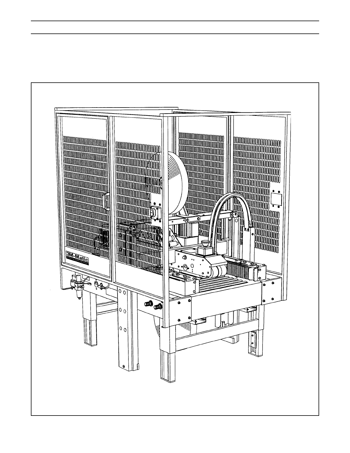
Section I 800r3 Random Case Sealer
Intended U e ................................................................................................................................... 1
Equipment Warranty and Limited Remedy ..................................................................................... 2
800r3 Content ............................................................................................................................... 2
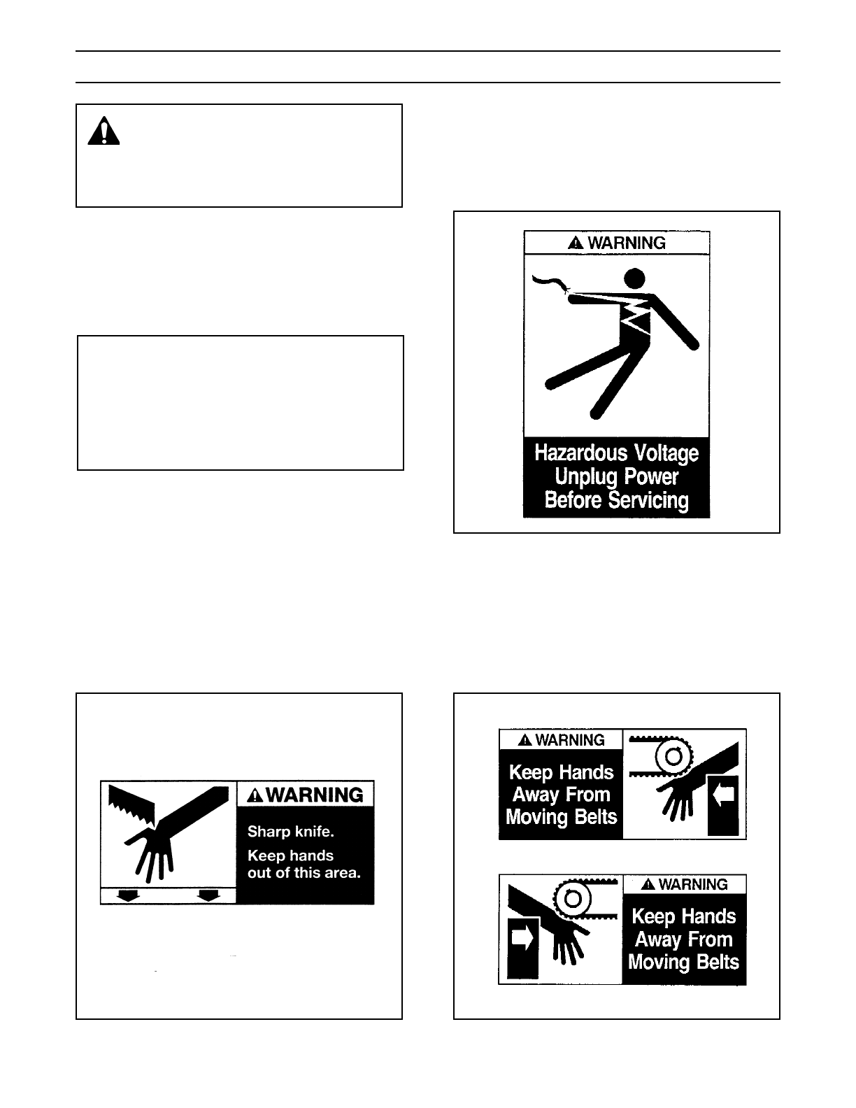
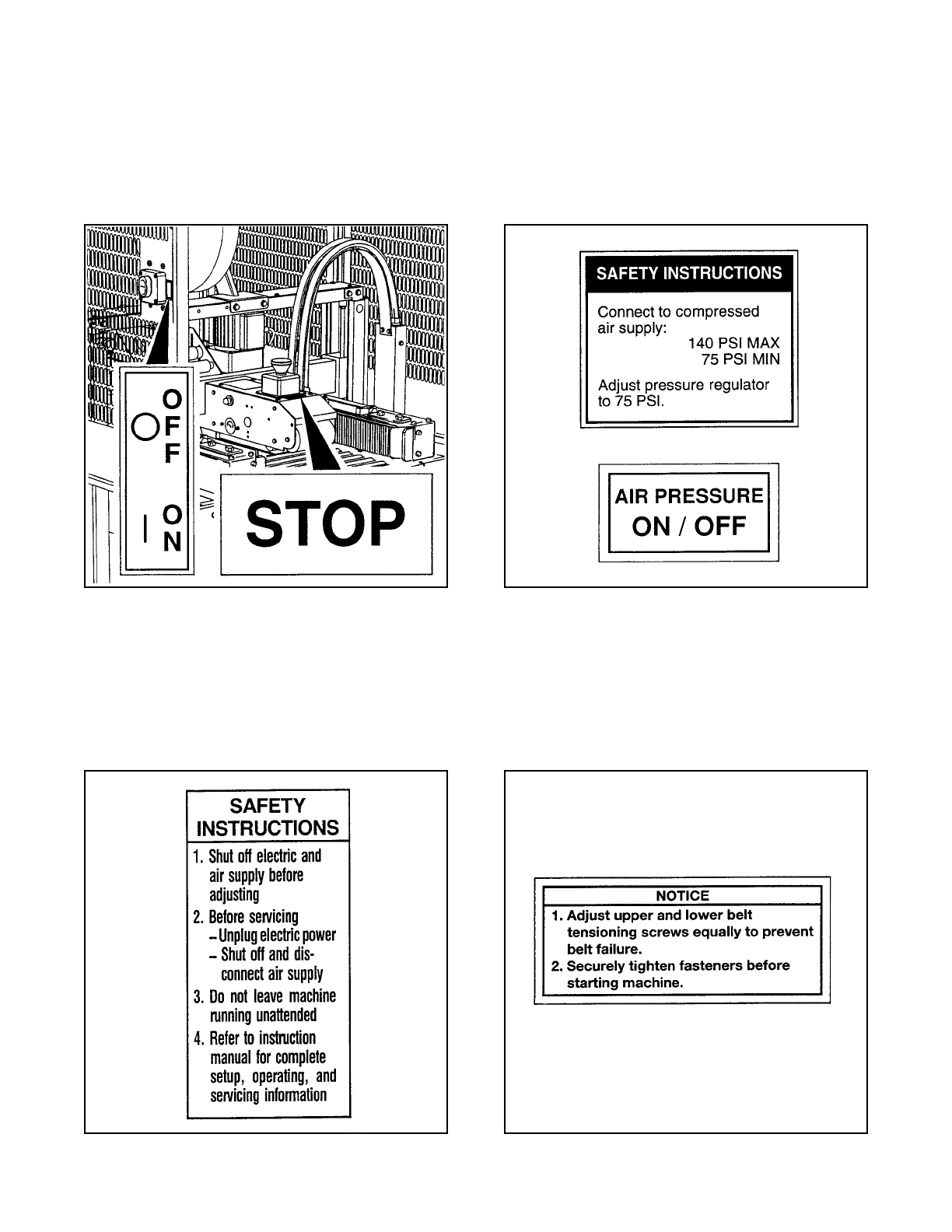
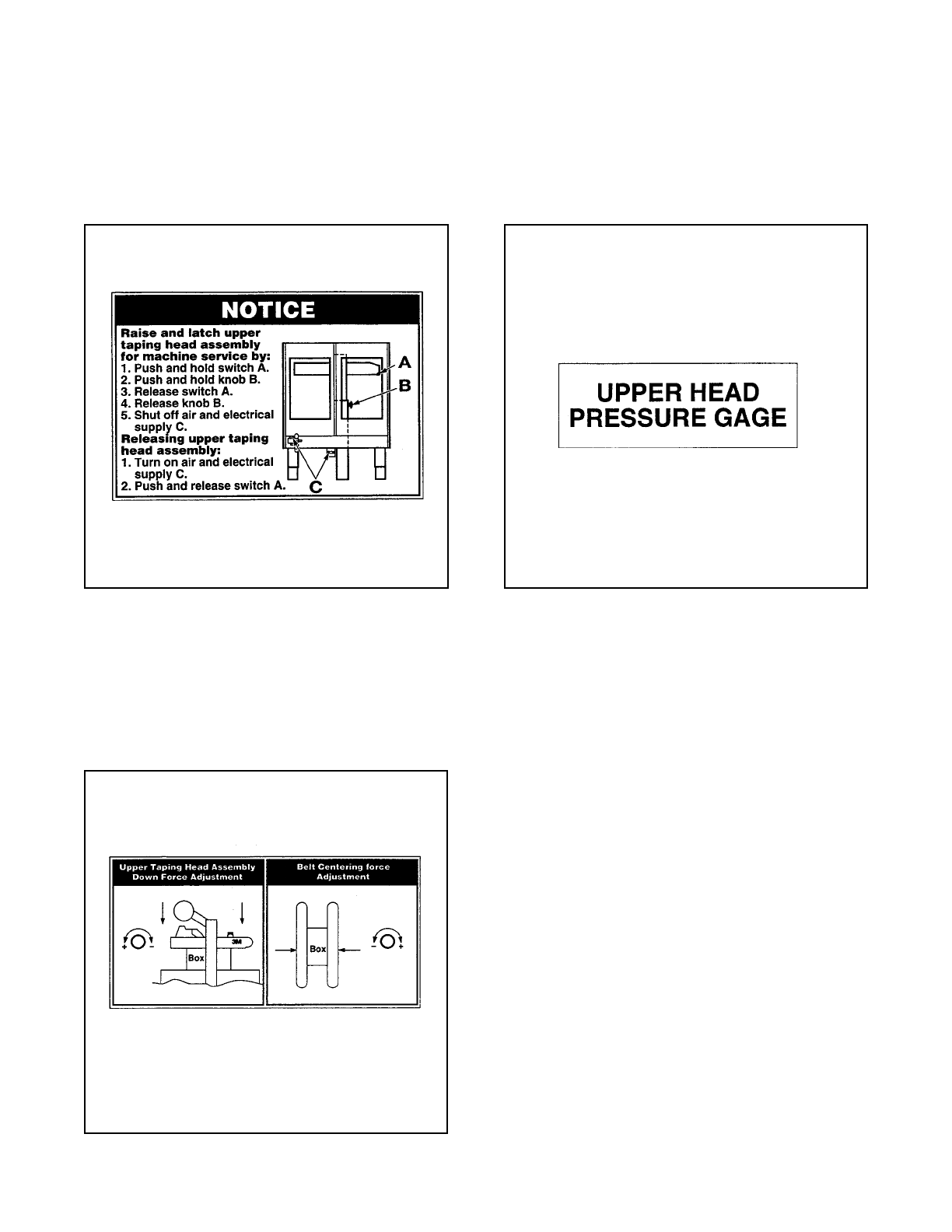
Important Safeguard ..................................................................................................................... 3 - 6
Specification .................................................................................................................................. 7 - 9
In tallation and Set-Up.................................................................................................................... 10 - 12
Receiving and Handling ..................................................................................... 10
Machine Set-Up ................................................................................................. 10 - 12
Packaging and Separate Part ................................................................. 10
Outboard Tape Roll Mounting .................................................................. 11
Tape Leg Length ...................................................................................... 11
Box Size Capacity of Ca e Sealer ........................................................... 11
Pneumatic Connection ............................................................................. 12
Electrical Connection and Control .......................................................... 12
Initial Start-Up of Ca e Sealer .................................................................. 12
Operation ........................................................................................................................................ 13 - 18
Control , Valve and Switche .......................................................................... 14 - 16
Tape Loading/Threading .................................................................................... 17
Box Sealing ........................................................................................................ 18
Box Jam ............................................................................................................. 18
Maintenance.................................................................................................................................... 19 - 22
Cleaning ............................................................................................................. 19
Lubrication.......................................................................................................... 19
Drive Belt .......................................................................................................... 20 - 21
Circuit Breaker ................................................................................................... 22
Knife Replacement, Taping Head ...................................................................... 22
Adju tment ................................................................................................................................... 23
Drive Belt Ten ion .............................................................................................. 23
Taping Head Adju tment .................................................................................. 23
(Table o Content continued on next page)
Instruction Manual
800r3 Random Case Sealer, Type 29600
Manual 1
Manual 2
Manual 2
Type 40800
3
Manual 1

ii
Table of Contents (Continued) Page
Special Set-Up Procedure .............................................................................................................. 24 - 25
Changing Tape Leg Length................................................................................ 24
Box Height Range .............................................................................................. 24 - 25
Trouble hooting................................................................................................................................ 27 - 28
Operating Sequence ........................................................................................................................ 29
Electrical Diagram ........................................................................................................................... 30 - 31
Pneumatic Diagram ......................................................................................................................... 32 - 33
Part and Service Information .......................................................................................................... 35
Option /Acce orie ....................................................................................................................... 36
Replacement Part Illu tration and Part Li t .................................................. Yellow Section 37 - 67
Section II AccuGlide II STD 3-Inch Taping Head
(See Section II for Table of Content )
Manual 1
Manual 2
3

1
The intended use of the 3M-MaticTM 800r3 Random Case Sealer with AccuGlideTM
II
Taping Heads is to apply a
C clip of ScotchTM brand pressure-sensitive film box sealing tape to the top and bottom center seam of regular
slotted containers. The case sealer automatically ad usts to a wide range of box sizes (see "Specifications
Box Weight and Size Capacities", page 8).
Intended Use
3M-MaticTM 800r3 Random Case Sealer, Type 29 00
Type 40800
3

2
(1) 800r3 Random Case Sealer, Type 29600
(1) Tool and Parts List
(1) Instruction and Parts Manual
ScotchTM, AccuGlideTM, and 3M-MaticTM are Trademarks of 3M, St. Paul, Minnesota 55144-1000
800r3 Contents
Equipment Warranty and Limited Remedy: THE FOLLOWING WARRANTY IS MADE IN LIEU OF ALL
OTHER WARRANTIES, EXPRESS OR IMPLIED, INCLUDING, BUT NOT LIMITED TO, THE IMPLIED WAR-
RANTY OF MERCHANTABILITY, THE IMPLIED WARRANTY OF FITNESS FOR A PARTICULAR PURPOSE
AND ANY IMPLIED WARRANTY ARISING OUT OF A COURSE OF DEALING, A CUSTOM OR USAGE OF
TRADE:
3M sells its 3M-Matic 800r3 Random Case Sealer, Type 29 00 with the following warranties:
1. The drive belts and the taping head knives, springs and rollers will be free from all defects for ninety
(90) days after delivery.
2. All other taping head parts will be free from all defects for three (3) years after delivery.
3. All other parts will be free from all defects for two (2) years after delivery.
If any part is proved to be defective within its warranty period, then the exclusive remedy and 3Ms and sellers
sole obligation shall be, at 3Ms option, to repair or replace the part, provided the defective part is returned
immediately to 3Ms factory or an authorized service station designated by 3M. A part will be presumed to have
become defective after its warranty period unless the part is received or 3M is notified of the problem no later
than five (5) calendar days after the warranty period. If 3M is unable to repair or replace the part within a
reasonable time, then 3M at its option, will replace the equipment or refund the purchase price. 3M shall have
no obligation to provide or pay for the labor required to install the repaired or replacement part. 3M shall have
no obligation to repair or replace (1) those parts failing due to operator misuse, carelessness, or due to any
accidental cause other than equipment failure, or (2) parts failing due to non-lubrication, inadequate cleaning,
improper operating environment, improper utilities or operator error.
Limitation of Liability: 3M and seller shall not be liable for direct, indirect, special, incidental or consequential
damages based upon breach of warranty, breach of contract, negligence, strict liability or any other legal
theory.
The foregoing Equipment Warranty and Limited Remedy and Limitation of Liability may be changed only by a
written agreement signed by authorized officers of 3M and seller.
Type 40800
Type 40800

3
Important Safeguards
The "Warning - Hazardous Voltage" label, shown
in Figure 1-2, is attached to the electrical enclosure
on the lower right side of the machine frame. The
label warns service personnel to unplug the power
supply before attempting any service work on the
case sealer.
Important In the event the following safety
labels are damaged or destroyed, they must be
replaced to ensure operator safety. A label
kit, part number 78-8113-6778-4 is available as
a stock item or individual labels can be ordered.
See Parts Illustration/List, Section I, pages 66
and 67.
Figure 1-3 Hands Warning Label
Figure 1-1 Knife Warning Label
Figure 1-2 Electrical Warning Label
The two "Warning Keep Away From Moving
Belts" labels, shown in Figure 1-3, are located on
each side of the top surface of the machine bed at
the infeed end. These labels warn operators and
service personnel to keep hands away from this
area when the drive belts are running.
Two "Warning Sharp Knife" labels, shown in
Figure 1-1, are attached to both sides of the upper
assembly at the location of the cut-off knife on the
upper taping head. The labels warn operators and
service personnel of the very sharp knife used to cut
the tape at the end of the tape application.
This safety alert symbol identifies
important messages in this manual.
READ AND UNDERSTAND THEM BEFORE
INSTALLING OR OPERATING THIS
EQUIPMENT.

4
Important Safeguards (Continued)
The "Stop" label, shown in Figure 1-4, is located in
front of the E-Stop switch and reminds operators
and casual personnel of the function of this switch.
In addition, an "On/Off" label is attached next to the
On/Off switch on the left machine guard at the
infeed end.
Figure 1-4 Stop and On/Off Labels
The "Safety Instructions" label, shown in
Figure 1- , is attached to the frame next to the air
valve/regulator and reminds operator of correct air
pressure to use. The "On/Off" label reminds
operators of the location of the pneumatic On/Off
valve.
Figure 1- Safety Instructions Label
The "Safety Instructions" label, shown in
Figure 1-5, is attached to the front of the upper
assembly. The label provides convenient safeguard
instructions for the operator and service personnel.
Figure 1-5 Safety Instructions Label
Two "Operating Notice" labels, shown in
Figure 1-7, are located on the top, infeed end of
both drive belt assemblies. The labels remind
operators of correct belt ad ustment procedures.
Figure 1-7 Operating Notice Label

5
Important Safeguards (Continued)
The "Raise/Latch" label, shown in Figure 1-8, is
attached to the upper, middle of the left machine
guard. The label provides quick reference
instructions for raising, latching and unlatching the
upper assembly.
Figure 1-8 Raise/Latch Upper Assembly Label
Figure 1-9 Force Adjustment Label
The "Force Adjustment" label, shown in
Figure 1-9, is attached to the left side of the
machine frame at the infeed end, The label
provides force ad ustment information for the upper
taping head assembly and belt centering.
The "Upper Head Pressure Gage" label, shown in
Figure 1-10, is attached to the upper assembly by
the air pressure gage.
Figure 1-10 Air Pressure Gage Label

6
Important Safeguards (Continued)
The following two labels are located on the upper
and lower taping heads. Replacement part
numbers for these labels are listed below each
label.
The "Warning-Sharp Knife" label warns operators
and service personnel of the extremely sharp knife
used to cut the tape at the end of the box sealing
operation. The label, shown in Figure 1-11, is
located on the orange knife guard between the
applying roller assembly and the buffing roller
assembly. Never operate taping heads with knife
guard removed.
Before working with the taping heads or loading/
threading tape, refer to Figures 3-1 and 3-2 in
Section II to identify the knife location. Keep hands
out of these areas except as necessary to
service the upper taping heads or to load/thread
tape.
The "Tape Threading Label", shown in
Figure 1-12, is attached to the left side of both the
upper and lower taping heads. This label provides a
convenient tape threading diagram. More detailed
tape loading and threading information is provided
in this manual in the set-up procedure section.
Figure 1-12 Tape Threading Label
Figure 1-11 Knife Warning Label
Manual 2

7
1. Power Requirements:
Electrical 115 VAC, 60 Hz, 3.8 A (440 watts)
Pneumatic 6.5 bar gauge pressure [95 PSIG]
110 litre/min @ 21° C, 1.01 bar
[3.75 SCFM] at 15 boxes per
minute
The machine is equipped with two 1/6 HP
gearmotors and comes with a 2.4 meter [8 ft]
long standard neoprene covered power cord
and a grounded plug. Contact your 3M
Representative for power requirements not
listed above.
2. Operating Rate:
Up to 15 boxes per minute. Actual production
rate is dependent on box size, box size mix, and
operator dexterity.
Box drive belt speed is 24 m/m [78 FPM]
3. Operating Conditions:
Use in dry, relatively clean environments at 4° to
50° C [40° to 120° F] with clean, dry, boxes.
Note Machine should not be washed down or
subjected to conditions causing moisture
condensation on components.
4. Tape:
ScotchTM brand pressure-sensitive film box
sealing tapes.
5. Tape Width:
48 mm [2.0 in] minimum to
72 mm [3.0 in] maximum
6. Tape Roll Diameter:
Up to 405 mm [16.0 in] maximum on a
76.2 mm [3.0 in] diameter core.
(Accommodates all system roll lengths of
ScotchTM brand film tapes.)
7. Tape Application Leg Length Standard:
70 mm ± 6 mm [2.75 in ±.25 in]
Tape Application Leg Length Optional:
(See "Special Set-Up Procedure", page 24)
50 mm ± 6 mm [2.00 in ±.25 in]
8. Box Board:
Style regular slotted containers RSC
125 to 275 P.S.I. bursting test, single wall or
double wall B or C flute.
(Specifications continued on next page)
4-SPECIFICATIONS
1. Power Requirements
Electrical: 115 Volt,60Hz, 3.8 A (440 watts)
The machine is equipped with a 2.4m [8 foot] standard neoprene covered power cord and a grounded plug.
Contact your 3M Representative for power requirements not listed above.
2. Operating Rate
Box drive belt speed is approximately 0.5 m/s [100 feet per minute].
5. Tape Width
36mm [1 1/2 inch] minimum to 50mm [2 inch] maximum
4. Tape
Scotch®pressure-sensitive film box sealing tapes.
3. Operating Conditions
Use in dry, relatively clean environments at 5oC to 50oC [40oF to 120oF] with clean, dry boxes.
Note: Machine should not be washed or subjected to conditions causing moisture condensation on
components.
0
5
10
15
20
25
30
35
40
45
0 5 10 15 20 25 30 35 40
Pneumatic – 5 bar gauge pressure [70 PSIG] 110 litre/min @ 21 C, 1.01 bar [3.75 SCFM] at 15 boxes per
minute A pressure regulator is included
• To reduce the risk associated with fire
and explosion hazards:
−Do not operate this equipment in poten-
tially flammable or explosive environments.
WARNING

(Specifications continued on next page.)
4-SPECIFICATIONS (continued)
Specifications
6. Tape Roll Diameter
Up to 405mm [16 inch] maximum on a 76.2mm [3 inch] diameter core.
(Accommodates all system roll lengths of Scotch® film tapes.)
7. Tape Application Leg Length – Standard
70mm ± 6mm [2 3/4 inch ±1/4 inch]
Tape Application Leg Length – Optional
50mm ± 6mm [2 inch ±. 1/4 inch]
(See "Removing Taping Heads Procedure – Changing the Tape Leg Length")
8. Box Board
Style – regular slotted containers – RSC
125 to 275 P.S.I. bursting test, single wall or double wall B or C flute.
23-44 lbs. per inch of width Edge Crush Test (ECT)
9. Box Weight and Size Capacities
A. Box Weight, filled: 5 lbs.– 65 lbs. [2.3 kg–29.5 kg]. Contents must support flaps.
B. Box Size: Minimum Maximum
Length – 205mm [8.0 inch] Unlimited
Width – 133mm [5.25 inch]*508mm [20.0 inch]
Height – 127mm [5.0 inch] 620mm [21.0 inch]
Outer Columns in Optional Raised Position
Minimum Maximum
Length – 205mm [8.0 inch] Unlimited
Width – 130mm [5.25 inch] 508mm [20.0 inch]
Height – 232mm [9.12 inch] 644mm [25.4 inch]
Note: The case sealer can accommodate most boxes within the size range listed above. However, if the box
length (in direction of seal) to box height ratio is 0.6 or less, test run several boxes to ensure proper
machine performance.
DETERMINE THE BOX LIMITATIONS BY COMPLETING THIS FORMULA:
BOX LENGTH IN DIRECTION OF SEAL = SHOULD BE GREATER THAN 0.6
BOX HEIGHT
Any box ratio approaching this limitation should be test run to ensure performance.

9
* Exit conveyor is optional
** Casters are optional
*** When columns are ad usted to upper position, "H" maximum dimension is 2062 mm [81.19 inches]. (See
"Special Set-Up Procedure Outer Column Re-Positioning", page 24)
Weight 225 kg [500 pounds] crated (approximate)
208 kg [460 pounds] uncrated (approximate)
11. Set-Up Recommendations:
Machine must be level.
Customer supplied infeed and exit conveyors (if used) should provide straight and level box entry and exit.
Exit conveyors (powered or gravity) must convey sealed boxes away from machine.
Specifications (Continued)
10. Machine Dimensions:
W W1 L H A* B C** F
Minimum
millimeters 970 1010 1180 1675 460 510 108 770
[Inches] [38.25] [39.75] [46.50] [66.00] [18.00] [20.00] [4.25] [30.38]
Maximum
millimeters 1955 690
[Inches] - - - - - - [77.00]*** - - [27.25] - - - -

10
Installation and Set-Up
After the machine has been uncrated, examine the
case sealer for damage that might have occurred
during transit. If damage is evident, file a damage
claim immediately with the transportation company
and also your 3M Representative.
Machine Set-Up
Important Read "Warnings" on page 17
before attempting to set-up the case sealer
for operation.
The following instructions are presented in the order
recommended for setting up and installing the case
sealer. Following them step by step will result in an
installation in your production line that best utilizes
the many features built into the case sealer. Refer
to Figures 3-1 and 3-2 to identify the various
components of the case sealer.
Receiving And Handling
Note A tool kit consisting of metric open end
and hex socket wrenches is provided with the
machine. These tools should be adequate to set-
up the machine however other tools supplied by
the customer will be required for machine mainte-
nance.
PACKAGING AND SEPARATE PARTS
1. Lift off fiberboard cover off pallet after removing
staples at bottom.
2. Remove protective wrapping around machine.
3. Remove hardware that secures case sealer legs
to pallet.
4. Cut cable ties that secure upper assembly to
machine bed on each side of machine. Remove
and discard cable ties and foam blocks.
5. Ensure that the tape drum bracket assembly,
located on the lower taping head, is mounted
straight down, as shown in Figure 2-1A. The
tape drum bracket assembly can be pivoted to
provide tape roll clearance in certain cases.
6. Use appropriate material handling equipment to
remove the machine from the pallet and move it
into position.
CAUTION Machine weighs
approximately 208 kg [4 0 pounds]
uncrated.
Note Minimum machine bed height can be
reduced to 400 mm [15.75 inch] by moving
outer columns up one set of mounting holes.
However this change also reduces minimum
box height of 127 mm [5.00 inch] to 232 mm
[9.12 inch]. (See "Special Set-Up Procedure
Outer Column Re-positioning" page 24.)
Refer to Figure 2-1C and set the machine bed
height as follows:
a. Use appropriate material handling
equipment and blocking techniques to raise
the machine frame to allow adequate leg
ad ustment.
b. Loosen, but do not remove, two M8 x 16
socket head screws in one leg (use M6 hex
wrench). Ad ust the leg length for the
desired machine bed height. Retighten the
two screws to secure the leg. Ad ust all four
legs equally.
7. Ad ust machine bed height. The case sealer is
equipped with four ad ustable legs that are
located at the corners of the machine frame.
The legs can be ad usted to obtain different
machine bed heights from 510 mm [20 in]
minimum to 690 mm [27.25 in] maximum.

11
Installation and Set-Up (Continued)
Figure 2-1 Conveyor Bed Height Adjustment and Lower Tape Drum Bracket Position
BOX SIZE CAPACITY OF CASE SEALER
At its factory setting, the case sealer handles
box sizes up to 533 mm [21.00 in] maximum
height. If larger capacity is needed, the
machine can be ad usted to accommodate
boxes up to 644 mm [25.38 in] high. Refer to
page 24, "Special Set-Up Procedures Outer
Column Re-positioning", for set-up procedure.
Note Adjusting machine to accommodate 644
mm [25.38 in] high boxes also increases
minimum box size to 232 mm [9.12 in].
OUTBOARD TAPE ROLL MOUNTING (Lower
Taping Head Alternate Position)
Remove the tape drum bracket assembly,
spacer and fasteners from the lower taping
head. Install and secure on the infeed end of
the lower frame, as shown in Figure 2-1B.
TAPING HEADS
Tape Width the taping heads have been pre-
set to accommodate 72 mm [3 inch] wide tape
rolls. To apply 48 mm [2 inch] or 42 mm
[1.75 inch] wide tapes, refer to Section II,
"Ad ustments Tape Web Alignment", page 11.
Tape Leg Length taping heads are pre-set to
apply 70 mm [2.75 in] long tape legs. To
change tape legs to 50 mm [2.0 inch], refer to
Section I, "Special Set-Up Procedure
Changing Tape Leg Length", page 24.
Manual 2

12
Installation and Set-Up (Continued)
ELECTRICAL CONNECTION AND CONTROLS
The electrical control box, located on the lower
right side of the machine frame, contains the
pre-set circuit breaker. The control box can be
located on the opposite side of the machine
frame if desired. A standard three conductor
power cord with plug is provided at the back of
the electrical control box for 115 Volt, 60 Hz, 6.4
Amp electrical service. The receptacle
providing this service shall be properly
grounded. Before the power cord is plugged
into 115 Volt, 60 Hz outlet make sure the red
"Off" button is depressed and that all packaging
materials and tools are removed from the
machine. Do not plug electrical cord into
outlet until ready to run machine.
Note Machines outside the U.S. may be
equipped with 220/240 Volt 50 Hz systems
or other electrical requirements compatible
with local practice.
INITIAL START-UP OF CASE SEALER
After completing the "Installation and Set-Up"
procedure, continue through "Operation" for
tape loading and start-up to be sure case sealer
is properly ad usted to run boxes.
PNEUMATIC CONNECTION
The case sealer requires a 6.5 bar gauge
pressure [95 PSIG], 110 litre/min @ 21° C,
1.01 bar [3.75 SCFM] compressed air supply.
Using customer supplied air hose (8 mm [.31 in]
I.D.) and clamp provided with machine, connect
plant air to barbed fitting on inlet side of
"On/Off" valve. See Figure 2-2. Note: If
another type of connector is desired the barbed
fitting can be replaced with the desired 1/4-18
NPT connector.
WARNING Use care when working
with compressed air.
Note The air valve has provisions for lock
out/tag out according to plant regulations.
Figure 2-2 Pneumatic Connection

13
Operation
IMPORTANT Before operating the case sealer, read the "Important Safeguards", pages 3- and
"Warnings" on page 17 as well as all of the "Operation" instructions.
Refer to Figure 3-1 and 3-2 to acquaint yourself with the various components and controls of the case sealer.
Also see Figures 3-1 and 3-2 in Section II for taping head components.
Figure 3-1 Case Sealer Components
Manual 2

27
Trou leshooting
The Troubleshooting Guide lists some possible machine problems, causes and corrections. Also see Section II
"Troubleshooting", pages 15 and 16 for taping head problems.
Troubleshooting Guide
Cause
Narrow boxes
Worn drive belts
Top taping head does not apply
enough pressure
Taping head applying spring
holder missing
Taping head applying spring set
too high
Worn or missing friction rings
Drive belt tension too low
Electrical disconnect
Circuit breaker not at correct
setting
Motor not turning
Worn belt
Dry compression rollers
Dry column bearings
Defective column bearings
Tape drum not centered
Drive belts not centered
Box flaps not of equal length
Correction
Check machine specifications.
Boxes are narrower than
recommended, causing slippage
and premature belt wear.
Replace drive belts
Ad ust the upper drive assembly
force ad ust regulator to increase
the force against the top of the
box. Turn air regulator
counterclockwise.
Replace spring holder
Reduce spring pressure
Replace friction rings
Ad ust belt tension
Check power and electrical plug
Set to correct current value
Evaluate problem and correct
Replace belt
Lubricate compression rollers
Lubricate column bearings
Replace column bearings
Reposition tape drum
Ad ust centering guides
Check box specifications
Problem
Drive belts do not convey boxes
Drive belts do not turn
Drive belts break
Squeaking noise as boxes pass
through machine
Tape not centered on box seam
(Continued)
Manual 2

15
Operation (Continued)
Figure 3-4 Air Regulator, Drive Belts
Figure 3-3 "On/Off" Valve/Regulator/Filter
3 E-Stop Switch
The E-Stop switch kills electrical power and
exhaust air pressure from the drive belt
assemblies. The upper head assembly will
raise to its upper most position. To restart
machine, rotate E-stop switch (releases switch
latch) and then restart machine by pressing
electrical switch "I" (On) button on side guard
of machine.
4Door
The door is equipped with a safety interlock
which kills electrical power and exhaust air
pressure from the drive belt assemblies. The
upper head assembly will raise to its upper
most position when the door is opened.
5 Raising Switch, Upper Taping Head Frame
This switch, when touched by the leading
edge of a box, pneumatically raises the upper
frame to allow insertion of a box under the
upper frame, as the box moves under the
switch, releasing it, the upper frame descends
on the box and the drive belts convey the box
through the machine. When switch is
actuated by hand, the upper frame rises to its
maximum height. Released, the upper frame
descends to its rest position.
WARNING The E-Stop switch or
door must not be used for raising
the upper head assembly for maintenance
work. If these are used the upper head
assembly could lower during maintenance
work causing injury to personnel.
Centering Switch, Box Drive Belts
This pneumatic switch controls the closing
(centering) of the drive belts. When switch is
activated by a box passing under it, the drive
belts close and center the box.
7Air Pressure Regulator, Box Drive Belt
Centering Figure 3-4.
This regulator is used to ad ust drive belt
centering pressure. The factory set point is 5
turns clockwise. If more pressure is needed to
center box, turn knob clockwise to desired
pressure. If box is being crushed, turn knob
counterclockwise to relieve pressure.
Regulator is locked by tightening screw.
8Air Pressure Gauge, Upper Taping Head
Frame
This gauge, used in con unction with the upper
frame air regulator, provides operator with a
reference pressure setting for various size/
weight boxes.
This manual suits for next models
1
Table of contents
Other 3M Power Tools Accessories manuals
Popular Power Tools Accessories manuals by other brands

Kreg
Kreg KMS7215 instructions

Triton
Triton AJA150 Operating and safety instructions

Matatakitoyo Torque Tools
Matatakitoyo Torque Tools MT2-4500N Operation manual

Kersten
Kersten WKB-H-K 35 Original operating instructions

HammerSmith
HammerSmith MultiTool Jigsaw Attachment Instructions for use

Festool
Festool CS 70 LA Assembly instruction