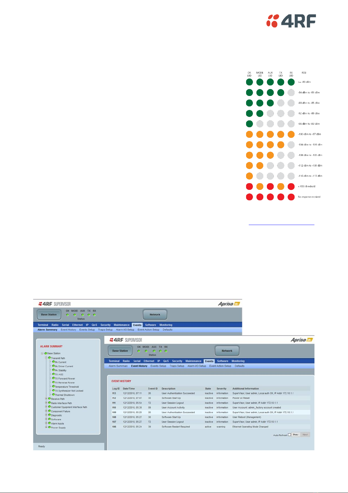
Connect to the Aprisa SRi Radio (via SuperVisor or CLI)
The Aprisa SRi has a factory default IP address of 169.254.50.10 with a subnet mask of 255.255.0.0.
Each radio in the Aprisa SRi network must be setup with a unique IP address on the same subnet.
If the IP address of the radio is known or is the default IP address, it can be changed via the Ethernet port:
•Setup your PC for a compatible IP address e.g. 169.254.50.1 with a subnet mask of 255.255.0.0.
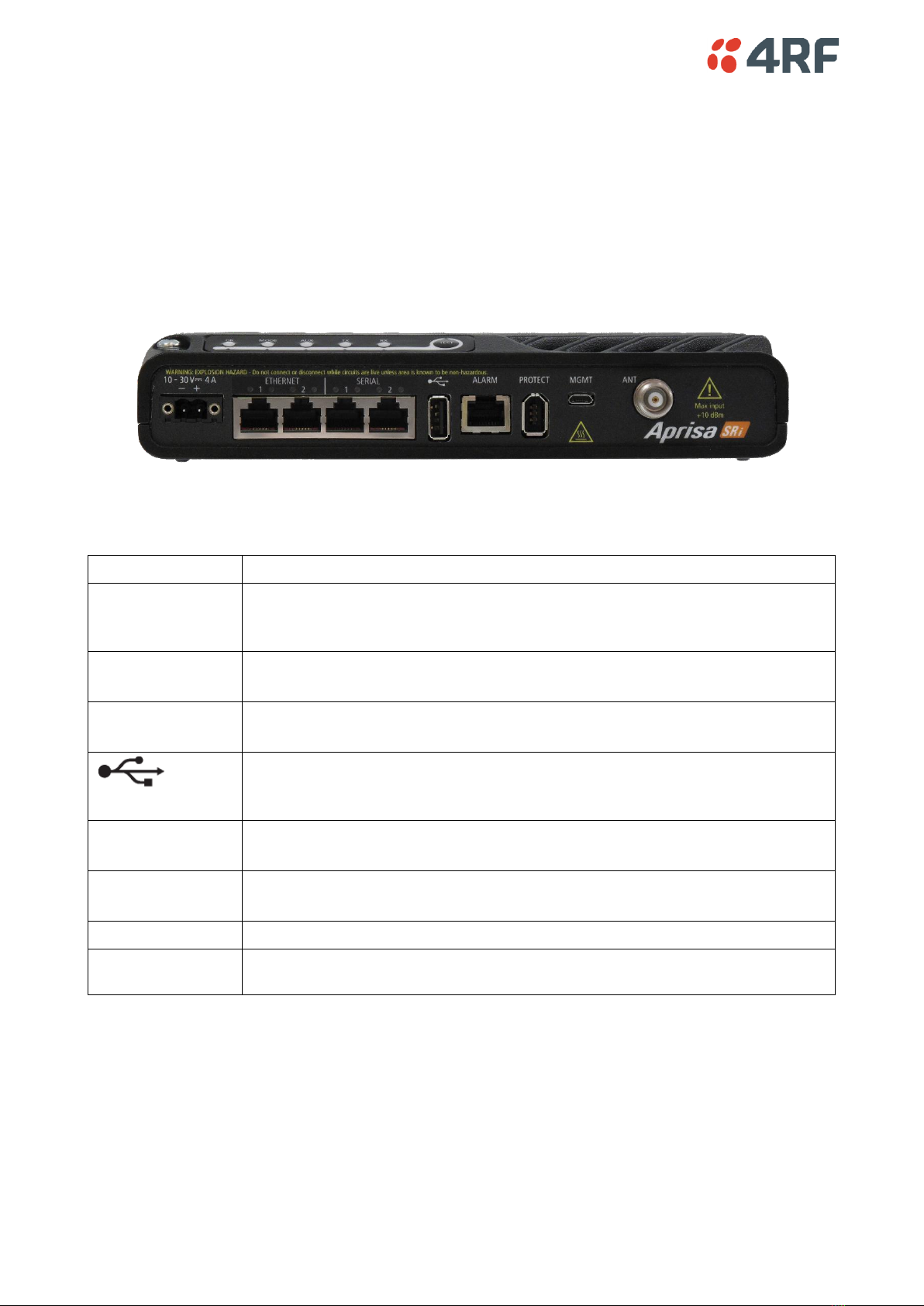
•Connect your PC network port to one of the Aprisa SRi Ethernet ports.
•Open a browser and enter https://169.254.50.10.
Note: The Aprisa SRi has a Self Signed security certificate which may cause the browser to prompt a certificate
warning. It is safe to ignore the warning and continue. The valid certificate is ‘Issued By: 4RF-APRISA’ which can be
viewed in the browser.
•Login to the radio with the default login ‘admin’ and password ‘admin’.
•Change the IP address, Subnet mask and Gateway to network compatible IP addresses.
If the IP address of the radio is unknown, it can be changed via the Command Line Interface on the radio MGMT USB port:
•Connect your PC USB port to the Aprisa SRi MGMT USB port. USB to UART Bridge VCP Drivers are required to connect
the radio USB port to your PC. You can download and install the relevant driver from
https://www.silabs.com/products/development-tools/software/usb-to-uart-bridge-vcp-drivers. Set the PC serial
port to 38,400 baud, 8 data bits, no parity and 1 stop bit, with no hardware flow control.
•Login to the radio with the default login ‘admin’ and password ‘admin’.
•At the command prompt >> type ‘cd APRISASR-MIB-4RF’ and enter.
- type ‘set termEthController1IpAddress xxx.xxx.xxx.xxx’ and enter.
- type ‘set termEthController1SubnetMask 255.255.0.0’ and enter.
- type ‘set termEthController1Gateway xxx.xxx.xxx.xxx’ and enter.