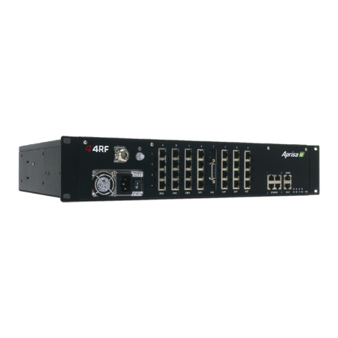
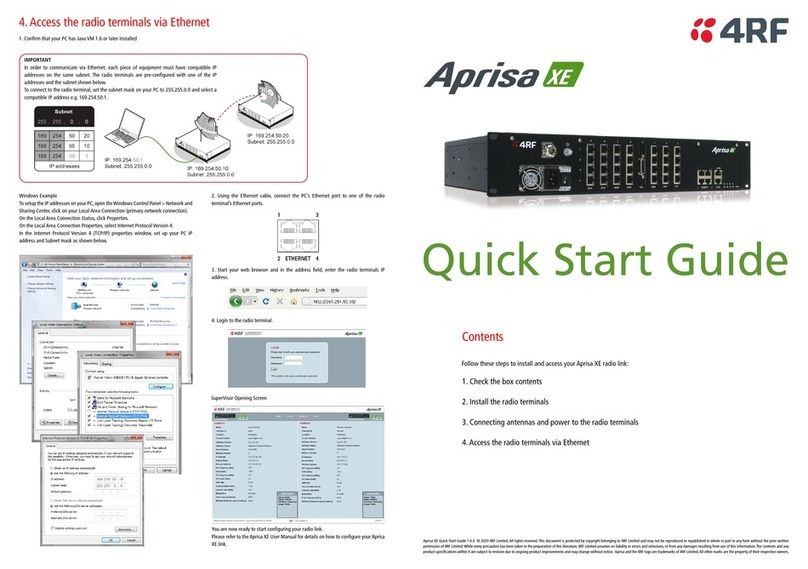
4RF Aprisa XE Quick reference guide

February 2009 Version 1.2
Radio Clocking Configuration
Aprisa XE Technical Paper

Aprisa XE Clocking Technical Paper 2 | 15 Issued by: 4RF Customer Services 13 February 2009
Table of contents
1. Radio Clocking.....................................................................................................................................................3
1.1. Introduction....................................................................................................................................................3
2. Clocking Setup.....................................................................................................................................................4
2.1. Internal...........................................................................................................................................................4
2.2. Link................................................................................................................................................................5
2.3. Network .........................................................................................................................................................6
2.3.1. QJET clocking setup...............................................................................................................................8
2.3.2. HSS clocking setup.................................................................................................................................8
3. External Clock Failure .........................................................................................................................................9
4. Network Clocking Examples.............................................................................................................................10
4.1. Single Link...................................................................................................................................................10
4.2. Back to back links –Unframed E1...............................................................................................................10
4.3. Back to back links –Framed E1..................................................................................................................11
4.4. 4 wire drop and insert..................................................................................................................................11
4.5. Branched Network - Mixed ..........................................................................................................................12
4.6. Central Master Clock...................................................................................................................................13
4.7. External E1 master clock.............................................................................................................................14
4.8. External HSS master clock..........................................................................................................................15
Aprisa XE Clocking Technical Paper 3 | 15 Issued by: 4RF Customer Services 13 February 2009
1. Radio Clocking
1.1. Introduction
This Technical Paper gives information on how to setup the clocking for the Aprisa XE radio in various
network configurations.
Setting the Aprisa XE clocking correctly is one of the most important aspects of network configuration.
Due to the versatility of the Aprisa XE it can be used in a number of different applications. This Technical
Paper has been created so that these situations can be better understood and the Aprisa XE set up
accordingly in your network.
All clocking configuration is done via the Aprisa XE SuperVisor software. See the Aprisa XE manual for
more detailed information on how to connect to an Aprisa XE radio via Ethernet.
This Technical Paper covers software version 8.2.10 and earlier.
Once SuperVisor is open radio clocking options can be accessed from the Clocking menu, as shown in
figure 1 below.
Figure 1 : Clocking Menu

Aprisa XE Clocking Technical Paper 4 | 15 Issued by: 4RF Customer Services 13 February 2009
2. Clocking Setup
2.1. Internal
To select internal as the radios clocking mode, select “Internal” from the Clock Source drop down box.
Once selected, click on the “Apply” button. This will apply the clocking changes to the radio.
Figure 2 : Internal Clocking Option

Aprisa XE Clocking Technical Paper 5 | 15 Issued by: 4RF Customer Services 9 December 2008
2.2. Link
To select link as the radios clocking mode, select “Link” from the Clock Source drop down box. Once
selected, click on the “Apply” button. This will apply the clocking changes to the radio.
Figure 3 : Link Clocking Option

Aprisa XE Clocking Technical Paper 6 | 15 Issued by: 4RF Customer Services 15 January 2009
2.3. Network
Selecting a Network clocking source is a two step process. First the radio must be set to Network clocking.
Then an interface must be configured as the network clock input.
Select “Network” from the Clock Source drop down box. Once selected, click on the “Apply” button.
Figure 4 : External Clocking Option
The next step involves selecting the external interface that the radio is to clock from, be it an E1/T1 or
HSS port.
Before setting up network clocks the cross-connect application must be started and a cross-connect
between the ports you wish to use as external clocks established.
Once cross-connections are made navigate to the interface page and select the card and then port which
you want to clock from, as shown in the figures below.
Figure 5 : Interface Summary menu
Select the slot of the card which you want to make the network clock source. Click on “Configure
Interfaces” button once selected.

Aprisa XE Clocking Technical Paper 7 | 15 Issued by: 4RF Customer Services 15 January 2009
Figure 6 : Card select
Select the port of the card which you want to make the network clock source. Click on “Edit” button once
selected. For HSS cards this step is not required as the HSS card only has a single port.
Figure 7 : Interface port select

Aprisa XE Clocking Technical Paper 8 | 15 Issued by: 4RF Customer Services 15 January 2009
Using the “Clock Source” drop down box, select the clock source type, primary or secondary. Then click
on the “Apply” button to make changes.
2.3.1. QJET clocking setup
Figure 8 : QJET port clock setting
2.3.2. HSS clocking setup
Figure 9 : HSS clock setting
Repeat the above process to set up a secondary external clock source if needed.

Aprisa XE Clocking Technical Paper 9 | 15 Issued by: 4RF Customer Services 15 January 2009
3. External Clock Failure
If the terminal Clock Source is set to Network, the terminal will automatically clock from the nominated
primary clock source if that clock source is available.
If the nominated primary clock source is not available, the terminal will clock from the nominated
secondary clock source if that clock source is available.
If the nominated secondary clock source is not available, the terminal will clock from the internal clock
source.
When a nominated clock source becomes available (primary or secondary), the terminal will then clock
from that clock source.

Aprisa XE Clocking Technical Paper 10 | 15 Issued by: 4RF Customer Services 15 January 2009
4. Network Clocking Examples
4.1. Single Link
Figure 10 : Single link network diagram
The above network is the simplest network possible. One radio is set to “Internal”clocking and the other
“Link”. The radio set to internal will generate an internal clock for timing. The radio set to “Link” will use the
clock extracted from data stream passed over the RF link.
4.2. Back to back links –Unframed E1
Figure 11 : Back to back unframed E1 network diagram
The above network uses a repeater site to pass the radio traffic between three sites. At the repeater site
the radios are interlinked via Unframed E1. As clocking information is carried across this E1 circuit the
next radio pair can be set to Internal and its partner Link.

Aprisa XE Clocking Technical Paper 11 | 15 Issued by: 4RF Customer Services 15 January 2009
4.3. Back to back links –Framed E1
Figure 12 : Back to back framed E1 network diagram
The above network uses a repeater site to pass the radio traffic between two sites. The radio at the local
site is set to internal and will generate the clocking for the entire network. The radios set to “Link” will
derive their clocking from the corresponding radio. At the repeater site the radios are interlinked via
framed E1. Because clocking information is not passed over a framed E1 the second radio link needs to
clock from the first radio link, in order to maintain synchronisation across the network. The radio at the
repeater site is set to External and is clocked of the incoming Framed E1 circuit.
4.4. 4 wire drop and insert
Figure 13 : Drop and insert 4 wire network diagram
The above network uses a repeater site to pass a 4 wire circuit between sites. This would be a typical
setup for 2 way radio site interlink, where keying of all sites at once is required. To facilitate the drop and
insert of the 4 wire circuits an external audio bridge is used.
As the traffic being transported is not digital, paired radios can be set to internal and link.

Aprisa XE Clocking Technical Paper 12 | 15 Issued by: 4RF Customer Services 15 January 2009
4.5. Branched Network - Mixed
Figure 14 : Branched network diagram
The above network uses a repeater site to pass E1 to two sites. In this case a mix of Framed E1 and
Unframed E1 is used. As in previous examples Framed E1 needs to have external clocking used.
Unframed E1 can have Internal clocking used.
The radios linking between the Repeater site and Remote 1 have clocking set to External / Link as
Framed E1 is being carried.
The radios linking between the Repeater site and Remote 2 have clocking set to Internal / Link as Framed
E1 is being carried.

Aprisa XE Clocking Technical Paper 13 | 15 Issued by: 4RF Customer Services 15 January 2009
4.6. Central Master Clock
Figure 15 : Central Master Clock
The above network uses a repeater site to pass Framed E1 to two sites. One radio at the repeater site is
set to “Internal” and is the clock source for the entire network.
As in previous examples Framed E1 needs to have external clocking used. So each radio pair going to
Remote 1 and Remote 2 have the clocking set to External and Link.

Aprisa XE Clocking Technical Paper 14 | 15 Issued by: 4RF Customer Services 15 January 2009
4.7. External E1 master clock
Figure 16 : External E1 master clock network diagram
The above network has external multiplexers which require the transport of Unframed E1. The Master
multiplexer at the “Local” site will provide the clocking for the entire network. The first radio clocks off the
Unframed E1 coming from the “Master Mux”with its clocking source set to External. The radio at the far
end of the link is set to “Link”. The multiplexer at the “Remote” site has to be set to “External” or “Receive”
clocking (naming dependant on manufacturer)
As clocking information is carried in the Unframed E1 the radios could also be set to Internal at the Local
site and Link at the Remote site.

Aprisa XE Clocking Technical Paper 15 | 15 Issued by: 4RF Customer Services 15 January 2009
4.8. External HSS master clock
Figure 17 : External HSS master clock
The above network has external devices which require the transport of High Speed Synchronise (HSS)
Data (X.21, V.35 etc). The Master device at the local site will provide the clocking for the entire network.
The first radio clocks off the HSS coming from the Master HSS device with its clocking source set to
External. At the repeater site the two radios are interconnected with Framed E1. Because of this, external
clocking needs to be used on the second repeater radio. The HSS device at the remote site needs to be
set to receive or external clocking (naming dependant on manufacturer).
Other manuals for Aprisa XE
6
Table of contents
Other 4RF Radio manuals

4RF
4RF Aprisa SR Plus User manual

4RF
4RF Aprisa SR+ User manual

4RF
4RF Aprisa SR Plus Technical specifications

4RF
4RF Aprisa XE User manual

4RF
4RF Aprisa SR User manual

4RF
4RF Aprisa SR+ User manual

4RF
4RF Aprisa SR+ User manual

4RF
4RF Aprisa SR+ Technical specifications

4RF
4RF Aprisa SR User manual

4RF
4RF Aprisa SR+ User manual