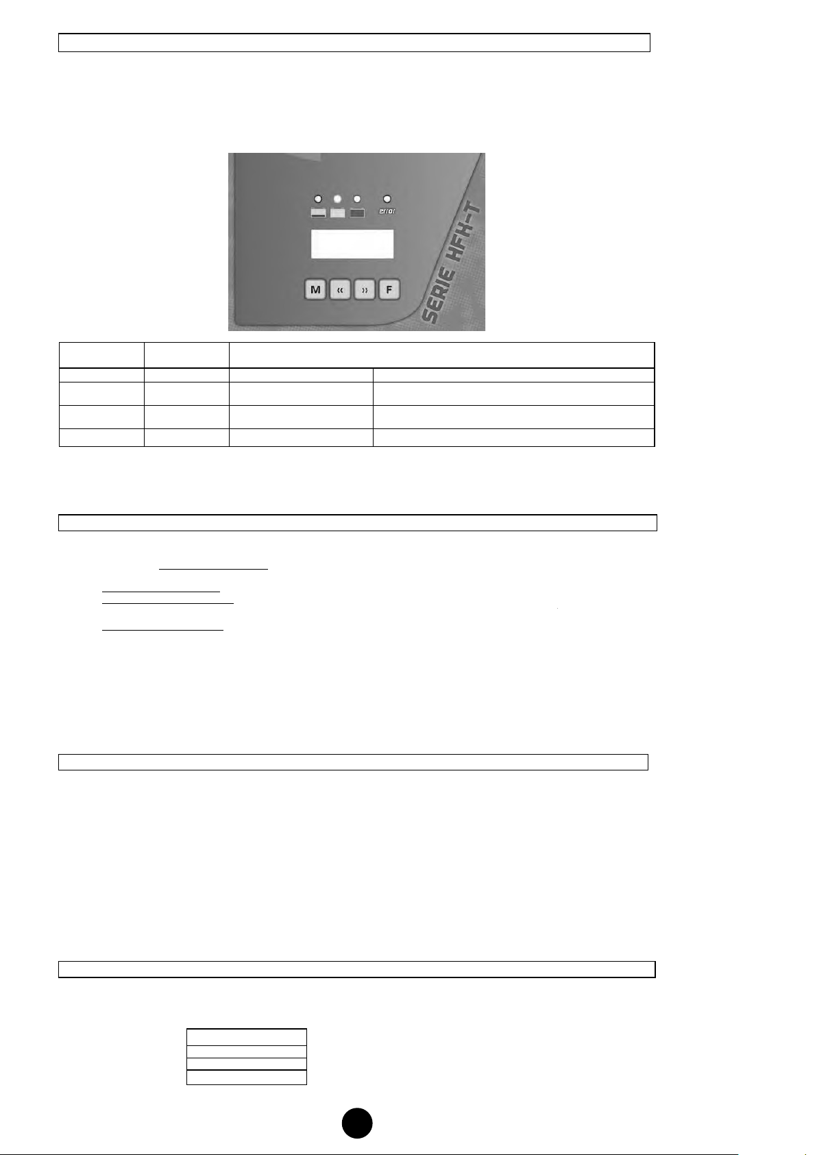
Charging phases visualisation
Charge phases display
Ac Mains Voltage on the battery charger missing
Initial phase of the charge with connected battery
having a voltage < 2,4 V/el*
Final Charge with battery voltage constant at 2,4
V/el* (phase V1)
Final Charge with constant current (phase I2)
Only for curve type LX –final charge with battery
voltage constant at 2,65V/el
*2,35 V/el for GEL batteries
Display functions
Forward scrolling of the parameters
Backwards scrolling of the parameters
Through keys <& >it is possible to scroll the following parameters:
Showing the voltage of the battery (Volt)
Showing the charging current (Ampere)
Elapsed time from the start of the charge(h)
Showing the total number of completed
charges
Showing the number of charges that lasted
more than 30’
Showing the code of an eventual alarm. E=0
indicates, no alarms
Showing nom capacity in Ah of battery to
charge
Showing the charging curve selected in the
charger
3. INSTALLATION
Please, read carefully the chapter “Warnings and safety”
The installation must be made in accordance with the following instructions. The operation must be made with the
electrical power disconnected.
3.1 Mounting Phase
1. Put the Battery Charger in a suitable place, allowing an adequate air change. Make sure the Battery Charger AC main
plug is accessible and well visible.
2. Connect the plugs, being very careful in earthling the AC side. Do not invert the battery polarity in comparison with
the Battery Charger. Models HFK with a power exceeding 3KW need a 32A singlephase plug 2P+earth.
3.2 Control Phase
1. Check the data on the charger identification plate, they must correspond with the mains and battery data.
2. Check that the power cables and the battery are well earthen.
3. Check there are no short circuits on plugs and cables.
3.3 Operating phase
1. Connect the battery plug
2. Connect the AC main plug
3.4 AIR Parameters (only for models equipped with this option)
AIR battery chargers control the pump function by a relay.
The pump is activated cyclically for period of 25s + 5s of pause.
It is possible to get more information at our offices (technical dept.) about how to modify the intervals of functioning of the
pump
Charging phases visualisation
L1 L2 L3 L4 Display
Ac Mains Voltage on the battery charger missing
Initial phase of the charge with connected battery
having a voltage < 2,4 V/el* ●-. --
Final Charge with battery voltage constant at 2,4
V/el* (phase V1) ●-. --
Final Charge with constant current (phase I2) -. --
Only for curve type LX –final charge with battery
voltage constant at 2,65V/el -. --
End of charge ●-. --
Preservation phase -. --
*2,35 V/el for GEL batteries
Display functions
Key Function
m Not in use
> Forward scrolling of the parameters
< Backwards scrolling of the parameters
F Not in use
Through keys <& >it is possible to scroll the following parameters:
Parameter Function Description
U --- Battery Voltage Showing the voltage of the battery (Volt)
A --- Battery current Showing the charging current (Ampere)
C --- Total Capacity Stored capacity (Ah)
t --- Total time Elapsed time from the start of the charge(h)
n --- Executed charges Showing the total number of completed
charges
N --- Partial charges Showing the number of charges that lasted
more than 30’
E. 0 Alarm Showing the code of an eventual alarm. E=0
indicates, no alarms
0--- Battery Capacity Showing nom capacity in Ah of battery to
charge
3.c -- Curve type Showing the charging curve selected in the
charger
3. INSTALLATION
Please, read carefully the chapter “Warnings and safety”
The installation must be made in accordance with the following instructions. The operation must be made with the
electrical power disconnected.
3.1 Mounting Phase
1. Put the Battery Charger in a suitable place, allowing an adequate air change. Make sure the Battery Charger AC main
plug is accessible and well visible.
2. Connect the plugs, being very careful in earthling the AC side. Do not invert the battery polarity in comparison with
the Battery Charger. Models HFK with a power exceeding 3KW need a 32A singlephase plug 2P+earth.
3.2 Control Phase
1. Check the data on the charger identification plate, they must correspond with the mains and battery data.
2. Check that the power cables and the battery are well earthen.
3. Check there are no short circuits on plugs and cables.
3.3 Operating phase
1. Connect the battery plug
2. Connect the AC main plug
3.4 AIR Parameters (only for models equipped with this option)
AIR battery chargers control the pump function by a relay.
The pump is activated cyclically for period of 25s + 5s of pause.
It is possible to get more information at our offices (technical dept.) about how to modify the intervals of functioning of the
pump
UK