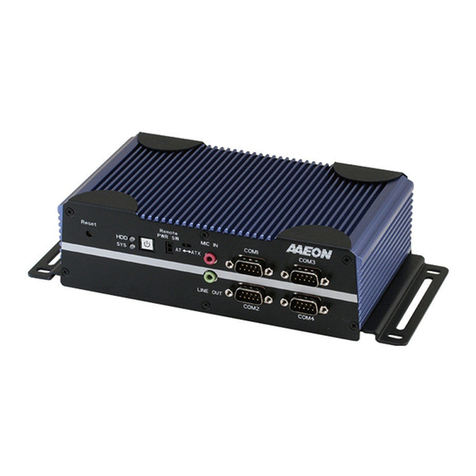
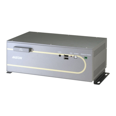
Aaeon GES-5500F User manual

Green Embedded System GES-5500F
GES-5500F
Green Embedded System
2.5” SATA Hard Disk Drive Bay
2 Gigabit Ethernet Ports/
4 COM / 8 USB2.0
GES-5500F Manual 1st Ed.
December 2010

Green Embedded System GES-5500F
i
Copyright Notice
This document is copyrighted, 2010. All rights are reserved. The
original manufacturer reserves the right to make improvements to the
products described in this manual at any time without notice.
No part of this manual may be reproduced, copied, translated, or
transmitted in any form or by any means without the prior written
permission of the original manufacturer. Information provided in this
manual is intended to be accurate and reliable. However, the original
manufacturer assumes no responsibility for its use, or for any in-
fringements upon the rights of third parties that may result from its
use.
The material in this document is for product information only and is
subject to change without notice. While reasonable efforts have been
made in the preparation of this document to assure its accuracy, WKH
PDQXIDFWXUHUassumes no liabilities resulting from errors or omissions in
this document, or from the use of the information contained herein.
The Manufacturer reserves the right to make changes in the product design
without notice to its users.

Green Embedded System GES-5500F
ii
Acknowledgments
All other products’ name or trademarks are properties of their
respective owners.
z Award is a trademark of Award Software International, Inc.
z Intel®, Core™ i7/i5/i3 are trademarks of Intel® Corporation.
z Microsoft Windows® is a registered trademark of Microsoft Corp.
z ITE is a trademark of Integrated Technology Express, Inc.
z IBM, PC/AT, PS/2, and VGA are trademarks of International
Business Machines Corporation.
z SoundBlaster is a trademark of Creative Labs, Inc.
All other product names or trademarks are properties of their
respective owners.

Green Embedded System GES-5500F
iii
Packing List
Before you begin installing your card, please make sure that the
following materials have been shipped:
• 1 GES-5500F Bare Bone
• 1 Product CD for manual (in PDF format) and drivers
• 1 CPU Heatsink
• 1 CPU Heatpipe Bracket
• 4 Memory thermal Pad
• 1 Memory Bracket
• 8 Screws for CPU heatsink and Memory Bracket
• 1 Southbridge (QM57) chip thermal Pad
• 1 Clock Generator thermal Pad
• 1 DIO male connector
• 1 3-pin DC-in male connector
If any of these items should be missing or damaged, please
contact your distributor or sales representative immediately.

Green Embedded System GES-5500F
iv
Contents
Chapter 1 General Information
1.1 Introduction................................................................ 1-2
1.2 Features .................................................................... 1-3
1.3 Specifications ............................................................ 1-4
1.4 General System Information ..................................... 1-6
Chapter 2 Quick Installation Guide
2.1 Location of Connectors and Jumpers ....................... 2-2
2.2 Mechanical Drawing.................................................. 2-4
2.3 List of Jumpers .......................................................... 2-5
2.4 List of Connectors ..................................................... 2-5
2.5 Setting Jumpers ........................................................ 2-7
2.6 CMOS Setting (CMOS1) ........................................... 2-8
2.7 Auto PWRBTN Selection (JP1)................................. 2-8
2.8 TPM Setting (JP3)..................................................... 2-8
2.9 COM1 +12V/+5V/RING Selection (JP5) ................... 2-8
2.10 COM2 +12V/+5V/RING Selection (JP6) ................. 2-8
2.11 Front Panel Connector (CN2) ................................. 2-9
2.12 SPI Programming Connector (CN3)........................ 2-9
2.13 CD-IN Pin Header (CN6)......................................... 2-9
2.14 RS-232/422/485 Pin Header (COM2) ..................... 2-9
2.15 RS-232 Pin Header (COM3~4) ............................. 2-10
2.16 Pin Header (USB3, USB4) .................................... 2-10
2.17 FAN Connector (FAN1, FAN2).............................. 2-10
Green Embedded System GES-5500F
v
2.18 4-pin ATX Power Connector (ATX1) ..................... 2-10
2.19 24-pin ATX Power Connector (ATX2)................... 2-10
2.20 SATA Connector (SATA 1~2) ............................... 2-11
2.21 Digital I/O Pin Header (DIO1)................................ 2-11
2.22 SATA Power Connector (PWR1) .......................... 2-12
2.23 Installing the Hard Disk Drive................................ 2-13
2.24 Installing the Memory ............................................ 2-17
Chapter 3 AMI BIOS Setup
3.1 System Test and Initialization. .................................. 3-2
3.2 AMI BIOS Setup ........................................................ 3-3
Chapter 4 Driver Installation
4.1 Installation ................................................................. 4-3
Appendix A Programming The Watchdog Timer
A.1 Programming .........................................................A-2
A.2 ITE8781 Watchdog Timer Initial Program..............A-7
Appendix B I/O Information
B.1 I/O Address Map ....................................................B-2
B.2 Memory Address Map............................................B-4
B.3 IRQ Mapping Chart................................................B-5
B.4 DMA Channel Assignments .................................B-5
Appendix C RAID & AHCI Settings
C.1 Setting RAID ......................................................... C-2
C.2 Setting AHCI ....................................................... C-12

Green Embedded System GES-5500F
Chapter 1 General Information 1- 1
General
Chapter
1
Information

Green Embedded System GES-5500F
1.1 Introduction
GES-5500F adopts the Intel® Core™ i7/i5/i3 Processor. The
chipset is equipped with Intel® QM57. Moreover, the system
memory features two DDR3 800/1066 SODIMM sockets up to 8 GB.
It deploys two LAN ports that consist of 10/100/1000Base-TX
Ethernet LAN RJ-45 ports. GES-5500F condensed appearance
features desktop and wallmount form factor that fits nicely into a
space-limited environment.
This compact GES-5500F equipped with one internal 2.5” Hard
Disk Drive with SATA 3.0 Gb/s interface. In addition, it features
four COM p orts and eight USB2.0 ports. F urthermore, the
GES-5500F deploys Intel® Gen 6.0 int egrated Graphics Engine
supports dual view by VGA, DVI, and HDMI.
Chapter 1 General Information 1- 2

Green Embedded System GES-5500F
1.2 Features
z Intel® 32/45nm Core™ i7/i5/i3 rPGA988 Processor With
Graphic And Memory Controller
z Fanless Design CPU TDP <35W, Intel® Core™ i7-620M And
i5-520M
z 204-Pin dual-Channel DDR3 800/1066 MHz SODIMM x 2, Up
To 8 GB
z Intel® Gen 6.0 Integrated Graphics Engine Supports Dual
View By VGA, DVI, HDMI
z Intel® PCI-Express 10/100/1000Base-TX x 2 (Support Intel®
AMT 6.0)
z USB 2.0 x 8, COM x 4
z Internal 2.5” Disk Drive Bay x 1
z Industrial Grade Robust Chassis, Fanless Design
z Wide DC Power Input: 10V DC~30V DC
Chapter 1 General Information 1- 3

Green Embedded System GES-5500F
1.3 Specifications
CPU Intel® Core™ i7/i5/i3
Chipset Intel® Core™ i7/i5/i3 + QM57
VGA D-Sub 15 x 1
DVI DVI-D x 1
Display
Interface Others HDMI x 1
SSD —
Storage
Device HDD 2.5” SATA HDD x 1
LAN 10/100/1000Base-TX x 2
Network Wireless Optional Mini-PCIe module x 1
USB Host USB 2.0 x 2
LAN —
Serial Port —
DIO 8-bit Programmable
Audio —
KB/MS —
Front I/O
Others —
USB Host USB 2.0 x 6
LAN RJ-45 x 2
Serial Port RS-232 x 3, RS-232/422/485 x 1
DIO —
Audio Line-in, Line-out, Mic-in
Rear I/O
KB/MS Keybarod x 1, Mouse x 1
Chapter 1 General Information 1- 4

Green Embedded System GES-5500F
Others Power-in
PCIe —
PCI —
Mini Card 1
Mini PCI —
Expansion
Others —
Front Power LED x 1, HDD LED x 1
Indicator Rear —
Power Requirement AC/DC power adapter
Power Consumption 70W
System Cooling Fanless
Mounting Desktop/ Wallmount
Operating Temperature 32oF ~133oF (0oC~45oC) (Automotive
HDD)
Storage Temperature -4oF ~140oF (-20oC~60oC)
Anti-Vibration HD: 0.5 g rms/5 ~500 Hz/ rando m
operation
Anti-Shock 15 G with 11 m/sec, operating
MTBF —
EMC CE/FCC Class A
Certification Safety —
Dimension 11.22” x 8.2 7” x 2.95” (285mm x
210mm x 75mm)
Gross Weight 11.16 lb (5.1 kg)
Note Windows® XP, Windows® 7, Linux
support
Chapter 1 General Information 1- 5

Green Embedded System GES-5500F
1.4 General System Information
Front Panel
Rear Panel
Chapter 1 General Information 1- 6

Green Embedded System GES-5500F
Chapter2HardwareInstallation2-1
Hardware
Installation
Chapter
2

Green Embedded System GES-5500F
2.1 Location of Jumpers and Connectors
Main board
Chapter 2 Hardware Installation 2-2

Green Embedded System GES-5500F
Chapter 2 Hardware Installation 2-3

Green Embedded System GES-5500F
2.2 Mechanical Drawing
DIO Pin Definition
Chapter 2 Hardware Installation 2-4

Green Embedded System GES-5500F
2.3 List of Jumpers
The board has a number of jumpers that allow you to configure your
system to suit your application.
The table below shows the function of each of the board's jumpers:
Label Function
CMOS1 CMOS Setting Selection
JP1 Auto PWRBTN Selection
JP3 TPM Setting Selection
JP5 COM1 +12V/+5V/RING Selection
JP6 COM2 +12V/+5V/RING Selection
2.4 List of Connectors
The board has a number of connectors that allow you to configure
your system to suit your application. The table b elow shows the
function of each board's connectors:
Label Function
CN1 DVI-I & COM Port Connector
CN2 Front Panel Connector
CN3 SPI Programming Connector
CN6 CD-IN
COM2 RS-232/422/485 Pin header
COM3~4 RS-232 Pin header
KM1 PS2 Keyboard/Mouse Connector
USB_LAN1 100/1000Base-TX Ethernet & Dual USB
Connector
USB_LAN2 100/1000Base-TX Ethernet & Dual USB
Connector
AUDIO1 Audio Lin-in/Lin-out/MIC
Chapter 2 Hardware Installation 2-5

Green Embedded System GES-5500F
DIMM1,DIMM2 DDR3 DIMM Slot
USB3,USB4 USB Pin header
FAN1, FAN2 4-pin System Fan Connector
ATX1 4-pin ATX Power +12V Connector
ATX2 24-pin ATX Power
SATA1~SATA2 SATA Connector
DIO1 Digital I/O
PIC1 PCI Slot
PCIE1 PCIE Slot
CN11 Mini-PCIE Slot
PWR1 SATA Power Connector
Chapter 2 Hardware Installation 2-6

Green Embedded System GES-5500F
2.5 Setting Jumpers
You configure your card to match th e needs of your application by
setting jumpers. A jumpe r is the simplest kind of el ectric switch. It
consists of two metal pins and a small metal clip (often protected by
a plastic cover) that slides over the pins to connect them. To “close”
a jumper you connect the pins with the clip.
To “open” a j umper you remove the clip. Sometimes a jumpe r will
have three pins, labeled 1, 2 and 3. In this case you would connect
either pins 1 and 2 or 2 and 3.
123
Open Closed Closed 2-3
A pair of needle-no se pliers may be helpful wh en working with
jumpers.
If you have any doubts about the b est hardware configuration for
your application, contact your local distributor or sales
representative before you make any change.
Generally, you simply n eed a sta ndard cable to make m ost
connections.
Chapter 2 Hardware Installation 2-7

Green Embedded System GES-5500F
2.6 CMOS Setting (CMOS1)
JP1 Function
1-2 Normal (Default)
2-3 Clear CMOS
2.7 Auto PWRBTN Selection (JP1)
JP1 Function
1-2 Don’t use Auto PWRBTN (Default)
2-3 Use Auto PWRBTN
2.8 TPM Setting (JP3)
JP3 Function
1-2 Save ME RTC Register (Default)
2-3 Clear ME RTC Register
2.9 COM1 +12V/+5V/RING Selection (JP5)
JP5 Function
1-2 +12V
3-4 Ring (Default)
5-6 +5V
2.10 COM2 +12V/+5V/RING Selection (JP6)
JP6 Function
1-2 +12V
3-4 Ring (Default)
5-6 +5V
Chapter 2 Hardware Installation 2-8
Table of contents
Other Aaeon Desktop manuals

Aaeon
Aaeon BOXER-6842M User manual

Aaeon
Aaeon BOXER-8233AI User manual

Aaeon
Aaeon AEC-6613 User manual

Aaeon
Aaeon BOXER-8220AI User manual

Aaeon
Aaeon AEC-6860 User manual

Aaeon
Aaeon BOXER-8110AI User manual

Aaeon
Aaeon BOXER-6839 User manual

Aaeon
Aaeon SIB-A8120 User manual

Aaeon
Aaeon EPIC-KBS9-PUC User manual

Aaeon
Aaeon AEC-6523 User manual

Aaeon
Aaeon BOXER-8521AI User manual

Aaeon
Aaeon BOXER-8410AI User manual

Aaeon
Aaeon FOX-120 User manual

Aaeon
Aaeon ACP-5185 User manual

Aaeon
Aaeon FES-6110 User manual

Aaeon
Aaeon AEV-6356 User manual

Aaeon
Aaeon AHP-1154 User manual

Aaeon
Aaeon AES-6000B User manual

Aaeon
Aaeon AEC-6637 User manual

Aaeon
Aaeon BOXER-6638U User manual