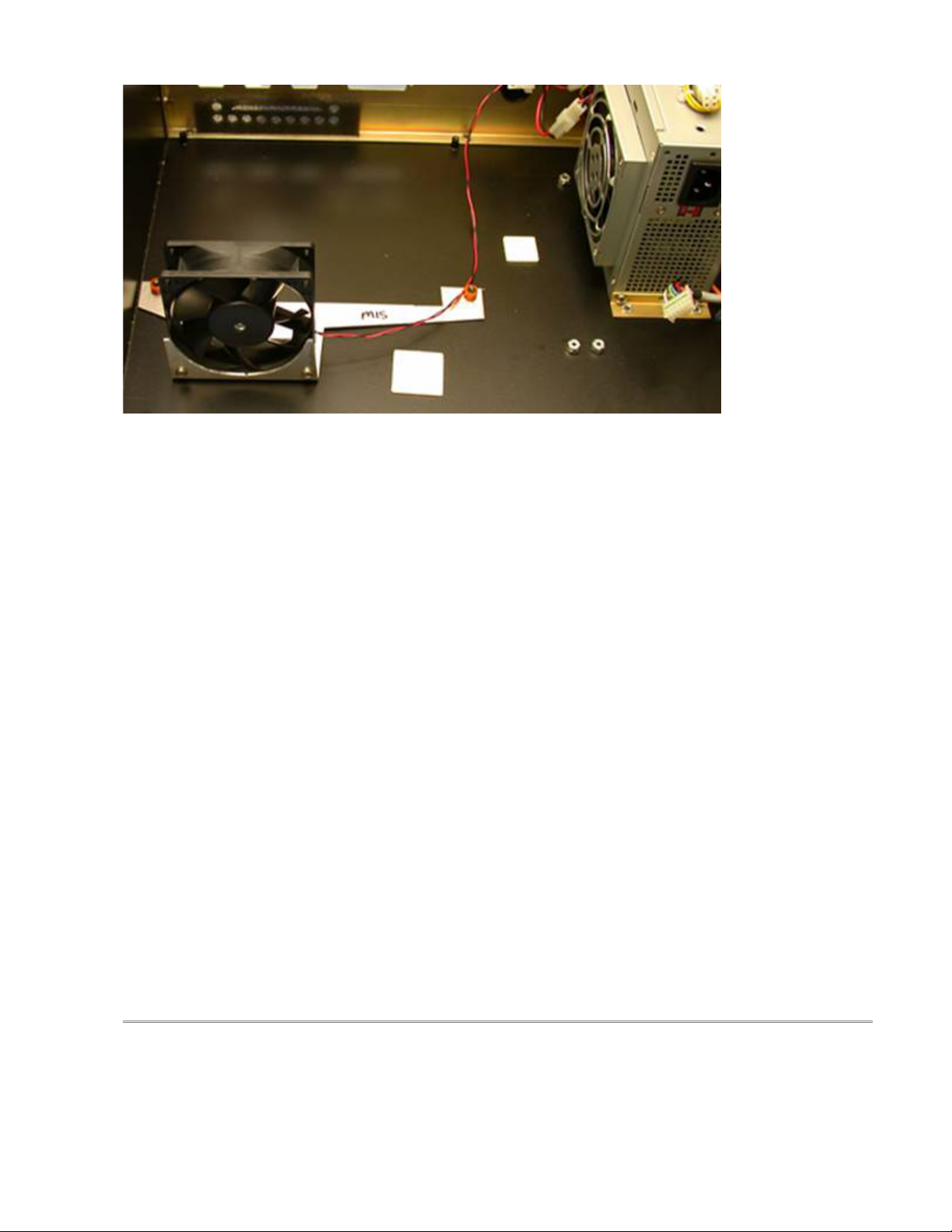
Picture 1: Cooling fan and bracket mounted in M15 console
2. Install the Aaeon motherboard on the existing motherboard standoffs at the bottom of the case. Refer to Picture 2 for
orientation.
3. Attach the new LCD Cable to CN3 on the motherboard and the other end to the LCD screen using the existing screws,
standoffs, and LCD Cable Mounting Bracket. The cable is keyed so, it can only be plugged in one way. The mounting
bracket goes over the LCD Connector to hold in place on the LCD.
4. Attach the Hard Drive cable to IDE1 on the motherboard. The red stripe goes to Pin 1, which is towards the CPU
Socket.
5. Attach the floppy drive cable to FDC1 on the motherboard (pin one closest to the standoff).
6. Attach the serial cable to CN6 on the motherboard. This socket is keyed and can only go on one way.
7. Attach the LPT1 cable to LPT1 on the motherboard. This socket is keyed and can only go one way.
8. Attach the USB cable to USB2 on the motherboard. Pin 1 is labeled with an Arrow and is the Red wire on the USB
Cable.
9. Connect new Ethernet cable to LAN1 on the motherboard.
10. Plug ATX power connector into PWR1. It will only plug in one way.
11. Connect the new keyboard/mouse cable to CN7. It will only connect one way.
12. After all cables are installed you will carefully need to route all the cables so that they do not obstruct the CPU7. The
LCD cable can be routed around the RAM as shown in Picture 2. Extra care must be taken with the ATX power
connector so that is does not interfere with the bottom of the CPU7 card.
13. If the M15 was not fitted with an ATX style power supply, then you will have to drill new mounting holes for the new
ATX power supply. Mount the ATX power supply as shown in Picture 1 above. Use the angled bracket and the pre-
existing bracket on the power supply to secure it to the console.
14. Power up console to verify MB will boot. You may need to go into the CMOS setup to change some settings. To do
this, hit the DEL key on the keyboard when the control does the Memory check. Go into STANDARD CMOS SETUP.
Change the Screen Resolution to 640x480 TT1. You must change the HALT option to ALL, BUT KEYBOARD. Go in to
the Power Management Setup and change PWRON after PWR-Fail to ON.
Note: If the motherboard was not setup at Centroid you may need to momentarily jumper pins 1 & 2 on CN9 while power
is applied to the motherboard. The motherboard will turn on and allow you to enter the BIOS. You must change the
power management as described above. Remove power before continuing with next step.


