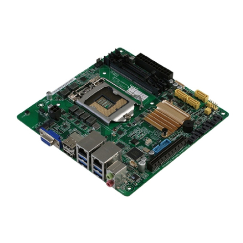
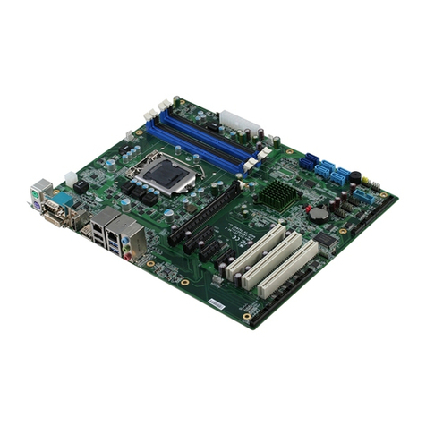
Aaeon EMB-900M User manual

Micro ATX Board EMB-900M
EMB-900M
Intel®Pentium®4 Processor,
Up to 3.2GHz
Micro ATX Board
With LCD and Ethernet,
7.1 Channel Audio & Mini PCI
EMB-900M Rev. A Manual 1st Ed.
June 2005

Micro ATX Board EMB-900M
i
Copyright Notice
This document is copyrighted, 2005. All rights are reserved. The original
manufacturer reserves the right to make improvements to the products
described in this manual at any time without notice.
No part of this manual may be reproduced, copied, translated, or
transmitted in any form or by any means without the prior written
permission of the original manufacturer. Information provided in this
manual is intended to be accurate and reliable. However, the original
manufacturer assumes no responsibility for its use, or for any in-
fringements upon the rights of third parties that may result from its use.
The material inthis document is for product information only and is
subject to change without notice. While reasonable efforts have been
made in the preparation of this document to assure its accuracy, AAEON
assumes no liabilities resulting from errors or omissions in this document,
or from the use of the information contained herein.
AAEON reserves the right to make changes in the product design without
notice to its users.

Micro ATX Board EMB-900M
ii
Acknowledgments
All other products’name or trademarks are properties of their respective
owners.
lAward is a trademark of Award Software International, Inc.
lCompactFlash™is a trademark of the Compact Flash Association.
lIntel®Pentium®4/ Celeron®Dis trademark of Intel®Corporation.
lMicrosoft Windows®is a registered trademark of Microsoft Corp.
lITE is a trademark of Integrated Technology Express, Inc.
lIBM, PC/AT, PS/2, and VGA are trademarks of International
Business Machines Corporation.
lSoundBlaster is a trademark of Creative Labs, Inc.

Micro ATX Board EMB-900M
iii
Packing List
Before you begin installing your card, please make sure that the
following materials have been shipped:
•1 EMB-900M CPU Card
•1 Quick Installation Guide
•1 CD-ROM for manual (in PDF format) and drivers
•1 40 pin IDE Cable
•1 34 pin FDD Cable
•1 Serial Port Cable
•3 SATA Cable
•3 SATA Power Cable
•2 USB Cable
•1 DVI to CRT Converter (Only for Model with DVI)
If any of these items should be missing or damaged, please contact
your distributor or sales representative immediately.

Micro ATX Board EMB-900M
iv
Contents
Chapter 1 General Information
1.1Introduction....................................................................................1-2
1.2Features............................................................................................1-4
1.3Specifications ..................................................................................1-5
Chapter 2 Quick Installation Guide
2.1 Safety Precautions..........................................................................2-2
2.2 Location of Connectors and Jumpers........................................2-3
2.3 Mechanical Drawing......................................................................2-6
2.4 List of Jumpers...............................................................................2-9
2.5 List of Connectors.......................................................................2-10
2.6 Setting Jumpers.............................................................................2-12
2.7 Audio Out Selection (JP1)..........................................................2-13
2.8 LCD Voltage Selection (JP4)......................................................2-13
2.9 Clear CMOS (JP5)........................................................................2-13
2.10 COM3Ring / +5V / +12V Selection (JP6).........................2-13
2.11 COM4 Ring / +5V / +12V Selection (JP8).........................2-14
2.12 CD-IN Connector (CN1).........................................................2-14
2.13 ATX Power_12V Connector (CN2)......................................2-14
2.14 LVDS Connector (CN3)...........................................................2-14
2.15 CPU Fan Connector (CN4).....................................................2-15
2.16 USB Connector (CN5, CN16).................................................2-15
2.17 Second Digital I/O Connector (CN6)...................................2-16

Micro ATX Board EMB-900M
v
2.18 First Digital I/O Connector (CN7)........................................2-16
2.19 Fan Connector (CN10, CN13)................................................2-16
2.20 Front Panel Connector (CN11)...............................................2-17
2.21 ATX-24 Power Connector (CN12)........................................2-17
2.22 RS-232/422/485 Serial Port Connector (CN14).................2-18
2.23 IrDA Connector (CN15)..........................................................2-19
2.24 Audio 7.1 Channel Connector.................................................2-19
Chapter 3 Award BIOS Setup
3.1 System Test and Initialization......................................................3-2
3.2 Award BIOS Setup........................................................................3-3
Chapter 4 Driver Installation
4.1 Step 1 –Install INF Driver.......................................................... 4-3
4.2 Step 2 –Install VGA Driver........................................................ 4-3
4.3 Step 3 –Install LAN Driver......................................................... 4-3
4.4 Step 4 –Install Audio Driver....................................................... 4-3
Appendix A Programming The Watchdog Timer
A.1 Programming...................................................................................A-2
A.2 IT8712 Watchdog Timer Initial Program.................................A-7
Appendix B I/O Information
B.1 I/O Address Map...........................................................................B-2
B.2 1st MB Memory Address Map..................................................... B-3
B.3 IRQ Mapping Chart...................................................................... B-4
B.4 DMA Channel Assignments........................................................ B-4
Micro ATX Board EMB-900M
Chapter 1 General Information 1 -1
General
Information
Chapter
1

Micro ATX Board EMB-900M
Chapter 1 General Information 1 -2
1.1 Introduction
The EMB-900M is AAEON’sfirst board that supports Intel®915GV
Express chipset. This is important breakthroughs for AAEON®in the
industrial environment domain.
High-Quality and Extreme Performance
With the flexibility to support the Intel®Pentium®4 processor 550 with HT
Technology and Intel®Celeron®D processor 340, the EMB-900M can offer
a scalable solution across different processing speeds. The EMB-900M also
provides an improved performance over previous solutions by incorporating
the Intel®915GV Express chipset. The DDR2 and PCI Express interface
are the newest technologies that allow the EMB-900M to providevery
high-speed bus bandwidth. By using PCI Express interface and adding
192KHz/7.1Channel HD Audio, the EMB-900M can bring a significant
increase in audio and visual performance in various applications. The
extended life motherboards that AAEON supplies to the industrial markets
offer functionality not available in off-the-shelf consumer motherboards,
such as High-Bandwidth Gigabit Ethernet Connectivity, 4 COM Ports and
optional ISA expansion slot.
Multimedia Function
The EMB-900M can be broadly implemented in various applications. It is
suitable for High-end POS/ KIOSK by taking advantage of the Intel®
GraphicsMedia Accelerator 900 (IntelGMA 900). It is also suitable for
Gigabit firewall and security applications thanks to its Gigabit-Ethernet

Micro ATX Board EMB-900M
Chapter 1 General Information 1 -3
Controller that utilizes a PCI-Express interface. The applicability extends to
Gaming and Entertainment Markets as well because of the 192K/24bit 7.1
Channel HD Audio via Intel®I/O Controller Hub 6.

Micro ATX Board EMB-900M
Chapter 1 General Information 1 -4
1.2Features
•Supports Intel®Pentium®4/Celeron D(LGA775) Processor
Up to 3.2GHz
•Supports CRT, LVDS and DVI Display
•Two Gigabit Ethernet Ports Support Based Upon PCI
Express Bus
•Supports 7.1 Channel High Definition Audio
•Supports Type II CompactFlash™ Memory
•2 PCI-E / 2 PCI / 1 Mini PCI / 1 Legacy ISA (Optional)
•4 COM / 8 USB 2.0 / Digital I/O Ports

Micro ATX Board EMB-900M
Chapter 1 General Information 1 -5
1.3 Specifications
System
lCPU: Supports Pentium®4 LGA775
Processor, up to 3.2GHz
lMemory:Dual Channel DDR-II 400/533,
Max. 4GB
lChipset: Intel®915GV + ICH6
lEthernet:Dual Marvell 88E8053,
10/100/1000 Base-TX RJ-45
lBIOS:AWARD 512KB FLASH ROM
lWatchdog Timer:Generate a time-out system reset
lH/W Status Monitoring: Supports power supply voltages,
fan speed and temperatures
monitoring
lSSD:Type II CompactFlash™slot x 1
lExpansion Interface:PCI slot x 2, PCI Express x 2,
Mini PCI x 1, ISA(Optional) x 1
lBattery:Lithium battery
lPower Supply Voltage: +3.3V, ±5V, +5VSB, ±12V,
ATX12V/ATX24P
lBoard Size:9.6”(L) x 9.6”(W) (244mm x
244mm)
lGross Weight: 1.32 lb (0.6kg)
lOperating Temperature: 32°F~140°F(0°C~60°C)

Micro ATX Board EMB-900M
Chapter 1 General Information 1 -6
Display
lChipset:Intel®915GV
lMemory: Shared memory up to 224MB with
DVMT 3.0
lResolutions:Up to 1600 x 1200
lDisplay Mode:Supports CRT/LCD, CRT/DVI,
LCD/DVI simultaneous display
lLCD Interface: Up to 48-bit dual channel LVDS,
DVI
I/O
lMIO: UDMA100 x 1, SATA x 3, Floppy
Disk Drive x 1, PS/2 Keyboard x 1,
PS/2 Mouse x 1, RS-232 x 3,
RS-232/422/485 x 1, Parallel x 1
lIrDA:One IrDA Tx/Rx header
lAudio:MIC-in, Line-in, Line-out, CD-in,
S/PDIF in/out, or 7.1 output
lUSB: Two Type-A(dual) connectors
support 4 USB 2.0 ports(External)
Two 5 x 2 pin header support 4
USB 2.0 ports(Internal)
lDigital I/O Supports up to 16 in and 16 out

Micro ATX Board EMB-900M
Chapter 2 Quick Installation Guide 2 -1
Quick
Installation
Guide
Chapter
2
Part No. 2007900M10Printed in Taiwan June 2005
Notice:
The Quick Installation Guide is derived
from
Chapter 2 of user manual. For other
chapters and
further installation
instructions
, please refer to the user
manual CD-ROM that ca
me with the
product.

Micro ATX Board EMB-900M
Chapter 2 Quick Installation Guide 2 -2
2.1 Safety Precautions
Always completely disconnect the power cord from
your board whenever you are working on it. Do not
make connections while the power is on, because a
sudden rush of power can damage sensitive
electronic components.
Always ground yourself to remove any static charge
before touching the board. Modern electronic
devices are very sensitive to static electric charges.
Use a grounding wrist strap at all times. Place all
electronic components on a static-dissipative
surface or in a static-shielded bag when they are not
in the chassis

Micro ATX Board EMB-900M
Chapter 2 Quick Installation Guide 2 -3
2.2Location of Connectors and Jumpers
Component Side –For DVI Interface
BATTERY
B3
A3
B2
A2
C1 C2
B1
A1
C0
E4
D4
F3
F2 F0
E1 E2 E3
D1 D3
D2
F4
C3 C4
B4
A4
F1
A25
A13
A14
A1
H1
123
H2 H1
123
H2
CN13
CN14
CN11
SATA1
CN16
SATA3
SATA2
JP6
JP8
CN15
MPCI1
IDE1
FDD1
CN12
DDRII 4
DDRII 3
DDRII 2
DDRII 1
CN10
CN4
CN2
KBMS1
SPDIF2
SPDIF1
DVI1
LPT1
USBRJ2
USBRJ1
AUDIO1
JP4 CN3
CN5
PCI-E1
PCI-E2
JP1
CN1
PCI1
PCI2
ISA1
JP5
JP7
CN8
CN9
CN6
CN7
24
8
16
17
1
9

Micro ATX Board EMB-900M
Chapter 2 Quick Installation Guide 2 -4
Component Side –For VGA Interface
BATTERY
B3
A3
B2
A2
C1 C2
B1
A1
C0
E4
D4
F3
F2 F0
E1 E2 E3
D1 D3
D2
F4
C3 C4
B4
A4
F1
A25
A13
A14
A1
H1
123
H2 H1
123
H2
CN13
CN14
CN11
SATA1
CN16
SATA3
SATA2
JP6
JP8
CN15
MPCI1
IDE1
FDD1
CN12
DDRII 4
DDRII 3
DDRII 2
DDRII 1
CN10
CN4
CN2
KBMS1
SPDIF2
SPDIF1
VGA1
LPT1
USBRJ2
USBRJ1
AUDIO1
JP4 CN3
CN5
PCI-E1
PCI-E2
JP1
CN1
PCI1
PCI2
ISA1
JP5
JP7
CN8
CN9
CN6
CN7

Micro ATX Board EMB-900M
Chapter 2 Quick Installation Guide 2 -5
Solder Side
1
CFD1

Micro ATX Board EMB-900M
Chapter 2 Quick Installation Guide 2 -6
2.3 Mechanical Drawing
Component Side –For DVI Interface
210.38
6.79
24
8
16
17
1
9
(174.73)
(10.00)
63.00
O3.51 - 9
BATTERY
B3
A3
B2
A2
C1 C2
B1
A1
C0
E4
D4
F3
F2 F0
E1 E2 E3
D1 D3
D2
F4
C3 C4
B4
A4
F1
A25
A13
A14
A1
H1
123
H2 H1
123
H2
0.00
0.00
6.37
6.36
11.19
4.02
121.29
2.54
7.62
149.86
141.08
150.23
2.64
4.45
157.48
0.00
223.52
214.63
231.14
3.18
168.68
160.43
29.21
47.63
72.39
223.52
157.48
72.39
212.09
228.60
213.06
192.74
196.22
203.20
227.33
237.48
237.47
187.69
127.83
145.61
163.39
181.17
174.98
191.90
154.66
171.45
167.01
157.48
229.87
215.27
210.19
147.69
190.06
136.54
196.71
172.72
134.62
215.36
148.81
220.27
120.40
98.30
218.00
35.69
24.00
227.71
57.90
220.58
6.99
230.00
189.87
3.18
204.47
0.00
72.39
0.00
80.65
4.45
98.19
145.33
95.33
148.19
77.88
168.42
5.87
96.41
216.54
68.58
28.58
10.80
(1.60)
(9.00)
(6.37)
(15.49)
(11.00)
(37.70)
(28.50)
(31.60)
(11.50)
(31.00)
(6.33)
(20.61)
(40.93)
(50.78)
(98.41)
(122.92)
(145.02)
(196.20)
(231.78)
(204.32)
(216.01)
198.84
79.57
161.84
103.32
(8.60)

Micro ATX Board EMB-900M
Chapter 2 Quick Installation Guide 2 -7
Component Side –For VGA Interface
210.38
6.79
O3.51 - 9
BATTERY
B3
A3
B2
A2
C1 C2
B1
A1
C0
E4
D4
F3
F2 F0
E1 E2 E3
D1 D3
D2
F4
C3 C4
B4
A4
F1
A25
A13
A14
A1
H1
123
H2 H1
123
H2
0.00
0.00
6.37
6.36
11.19
4.02
121.29
2.54
7.62
149.86
141.08
150.23
2.64
4.45
157.48
0.00
223.52
214.63
231.14
3.18
168.68
160.43
29.21
47.63
72.39
223.52
157.48
72.39
212.09
228.60
213.06
192.74
196.22
203.20
227.33
237.48
237.47
187.69
127.83
145.61
163.39
181.17
174.98
191.90
154.66
171.45
167.01
157.48
229.87
215.27
210.19
147.69
190.06
136.54
196.71
172.72
134.62
215.36
148.81
220.27
120.40
98.30
218.00
63.00
35.69
24.00
227.71
57.90
220.58
6.99
230.00
189.87
3.18
204.47
0.00
72.39
0.00
80.65
4.45
98.19
145.33
95.33
148.19
77.88
168.42
5.87
96.41
216.54
68.58
28.58
10.80
(1.60)
(9.00)
(6.37)
(15.49)
(11.00)
(37.70)
(28.50)
(31.60)
(12.55)
(11.50)
(31.00)
(6.33)
(20.61)
(40.93)
(50.78)
(98.41)
(122.92)
(145.02)
(196.20)
(231.78)
(174.47)
(204.32)
(216.01)
198.84
79.57
161.84
103.32
(8.60)

Micro ATX Board EMB-900M
Chapter 2 Quick Installation Guide 2 -8
Solder Side
1
0.00
0.00
6.37
6.36
223.52
157.48
0.00
72.39
223.52
157.48
227.33
203.20
157.48
168.42
77.88
5.87
96.41
0.00
72.39
204.47
0.00
145.33
98.19
148.19
95.33
79.57
198.84
103.32
161.84
21.91
199.36
Other manuals for EMB-900M
1
Table of contents
Other Aaeon Motherboard manuals

Aaeon
Aaeon EMB-A70M User manual

Aaeon
Aaeon EMB-LN9T Rev.B User manual

Aaeon
Aaeon PCM-4335 User manual

Aaeon
Aaeon UPC-Plus User manual

Aaeon
Aaeon HSB-LN2I User manual

Aaeon
Aaeon IMBM-H110A User manual

Aaeon
Aaeon EMB-852T User manual

Aaeon
Aaeon EMB-BT1 User manual

Aaeon
Aaeon EPC-CV1 Series User manual

Aaeon
Aaeon VIA Eden Series User manual

Aaeon
Aaeon GENE-QM77 User manual

Aaeon
Aaeon PCM-6893 User manual

Aaeon
Aaeon MIX-Q370D1 User manual

Aaeon
Aaeon MIX-Q370D2 User manual

Aaeon
Aaeon EMB-APL1 User manual

Aaeon
Aaeon PCM-8152 3rd Generation User manual

Aaeon
Aaeon EPIC-9457 User manual

Aaeon
Aaeon IMBI-Q57 User manual

Aaeon
Aaeon EMB-945T User manual

Aaeon
Aaeon UP 400 EDGE User manual