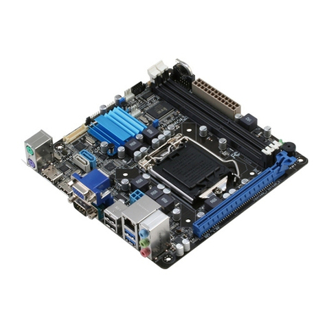
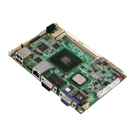
Aaeon XTX-915 User manual

XTX CPU Module XTX-915
XTX-915
Intel
®Pentium®M/
Celeron®M Processor
DDRII SODIMM
With LCD, Ethernet, PCI-E,
Audio, SATA, SDVO
XTX-915 Manual Rev. A 2nd Ed.
June 2008

XTX CPU Module XTX-915
i
Copyright Notice
This document is copyrighted, 2008. All rights are reserved. The
original manufacturer reserves the right to make improvements to
the products described in this manual at any time without notice.
No part of this manual may be reproduced, copied, translated, or
transmitted in any form or by any means without the prior written
permission of the original manufacturer. Information provided in this
manual is intended to be accurate and reliable. However, the
original manufacturer assumes no responsibility for its use, or for
any infringements upon the rights of third parties that may result
from its use.
The material in this document is for product information only and is
subject to change without notice. While reasonable efforts have
been made in the preparation of this document to assure its
accuracy, AAEON assumes no liabilities resulting from errors or
omissions in this document, or from the use of the information
contained herein.
AAEON reserves the right to make changes in the product design
without notice to its users.

XTX CPU Module XTX-915
ii
Acknowledgments
All other products’ name or trademarks are properties of their
respective owners.
Award is a trademark of Award Software International, Inc.
Intel®, Pentium®M and Celeron®M are trademarks of Intel®
Corporation.
Microsoft Windows®is a registered trademark of Microsoft
Corp.
ITE is a trademark of Integrated Technology Express, Inc.
IBM, PC/AT, PS/2, and VGA are trademarks of International
Business Machines Corporation.
Please be notified that all other products’ name or trademarks not
be mentioned above are properties of their respective owners.

XTX CPU Module XTX-915
iii
Packing List
Before you begin installing your card, please make sure that the
following materials have been shipped:
• 1 XTX-915 CPU Module
• 1 CD-ROM for manual (in PDF format) and drivers
• 4 M2.5 Screws
If any of these items should be missing or damaged, please contact
your distributor or sales representative immediately.

XTX CPU Module XTX-915
iv
Application Note
1. Intel Banias-core CPUs on XTX-915
TF-XTX-915-A10 supports Intel Dothan-core CPUs only. Please do
not use Intel Banias-core CPUs on TF-XTX-915-A10. It may cause
the damage of CPUs. If you want to use Intel Banias-core CPUs,
some components on XTX-915 have to be changed. Please contact
with your AAEON responsible sales for this specific requirement.
2. Display issue of 640x480 LVDS LCD panel
If you use 640x480 LVDS LCD panel and Intel Graphics Utility to set
the Extended Desktop mode, the panel will show nothing.
For more detailed information, please contact with AAEON
Application Engineer Department.
FAQ
Question: How do I install the OS into SATA HDD when I choose
the “Enhanced Mode” in the BIOS for HDD setting?
Answer: If you are going to use SATA and IDE HDD
simultaneously, please follow the steps below to install OS properly.
Step 1: Choose the “Enhanced Mode” in the BIOS
Step 2: Connect SATA HDD only
Step 3: Install OS
Step 4: Connect IDE HDD
Please be noted that you cannot connect SATA and IDE HDD to
install OS at the same time since the OS installation may fail.

XTX CPU Module XTX-915
v
Contents
Chapter 1 General Information
1.1 Introduction................................................................1-2
1.2 Features....................................................................1-3
1.3 Specifications............................................................1-4
Chapter 2 Quick Installation Guide
2.1 Safety Precautions....................................................2-2
2.2 Mechanical Drawing..................................................2-3
2.3 List of Jumpers..........................................................2-5
2.4 List of Connectors .....................................................2-6
2.5 Setting Jumpers ........................................................2-7
2.6 BIOS Write Protect (JP1) (Non-populated)...............2-8
2.7 SDVO Port Connector (CN2)....................................2-8
2.8 XTX Connector (XTX-1)............................................2-9
2.9 XTX Connector (XTX-2)..........................................2-10
2.10 XTX Connector (XTX-3)........................................2-11
2.11 XTX Connector (XTX-4)........................................2-12
Chapter 3 Award BIOS Setup
3.1 System Test and Initialization. ..................................3-2
3.2 Award BIOS Setup....................................................3-3
Chapter 4 Driver Installation
4.1 Installation.................................................................4-3

XTX CPU Module XTX-915
vi
Appendix A Programming The Watchdog Timer
A.1 Programming .........................................................A-2
A.2 IT8712 Watchdog Timer Initial Program................A-6
Appendix B I/O Information
B.1 I/O Address Map....................................................B-2
B.2 1st MB Memory Address Map ................................B-3
B.3 IRQ Mapping Chart................................................B-4
B.4 DMA Channel Assignments...................................B-4

XTX CPU Module XTX-915
Chapter 1 General Information 1 - 1
General
Chapter
1
Information

XTX CPU Module XTX-915
Chapter 1 General Information 1 - 2
1.1 Introduction
XTX-915 equips with Intel®Pentium®M / Celeron®M processors
and has one 200-pin DDR II 400/533 SODIMM to support system
memory up to 2GB. XTX-915 adopts Intel®915GME+ ICH6-M
chipset that implements serial technologies with high performance.
In addition, XTX-915 accommodates user-friendly expansion
interfaces, such as four PCI-Express[x1], four 32-bit PCI, one LPC
bus, one SMBus and one I2C interface.
For the display specifications, XTX-915 integrates Intel®915GME
and shared system memory is up to 128MB. The display of
XTX-915 supports CRT and 18-bit dual-channel LVDS LCD.
Moreover, one SDVO port can be used through the SDVO
connector to provide more flexibility for display function.
If you are looking for an economic, time-saving and high
performance solution, XTX-915 definitely is your best choice.

XTX CPU Module XTX-915
Chapter 1 General Information 1 - 3
1.2 Features
Intel®Pentium®M/ Celeron®M Processors
DDR II 400/533 Memory
CRT/ 18-bit Dual-channel LVDS LCD
10/100Base-TX Ethernet
AC97 Audio Codec
PCI-Express[x1]x 4
SATA x 2
SDVO Connector x 1
+5V Operating Voltage
XTX Form Factor

XTX CPU Module XTX-915
Chapter 1 General Information 1 - 4
1.3 Specifications
System
CPU Intel®(Socket 478-based) Pentium®M
Celeron®M Processors
Memory One 200-pin DDR II SODIMM, supports
DDR II 400/533 up to 2GB
Chipset Intel®915GME+ICH6-M
Ethernet Intel 82562ET, 10/100Base-TX
BIOS Award, PLCC type, 1MB ROM
Watchdog Timer Generates a Time-out System Reset
H/W Status Monitoring Supports Power Supply Voltages, Fan
Speed and Temperature Monitoring
Wake on LAN Yes
Expansion Interface PCI-E[x1]x4
32-bit PCI x 4
LPC Bus x 1
SMBus x 1
I2C x 1
Power Supply Voltage +5V DC
Board Size 4.5”(L) x 3.74”(W) (114mm x 95mm)
Gross Weight 0.66lb (0.3kg)
Operating Temperature 32°F~140°F (0°C~60°C)
Storage Temperature -40°F~176°F (-40°C~80°C)

XTX CPU Module XTX-915
Chapter 1 General Information 1 - 5
Display: Supports CRT/LCD, simultaneous/ dual independent
display
Chipset Intel®915GME integrated
Memory Shared system memory up to 128MB
Resolution Up to 2048x1536 (QXGA) for CRT; Up to
1600x1200 (UXGA),
1920x1200(WUXGA) for LCD
LCD Interface
SDVO Port
18-bit dual-channel LVDS
One SDVO port can be used through the
SDVO connector
I/O
Storage PATA x 1 channel (2 devices), SATA x 2
Serial Port 2
Parallel Port 1
USB USB2.0 x 6
PS/2 Port Keyboard x 1, Mouse x 1
IrDA One IrDATx/Rx header
Audio Mic-in, Line-in, Line-out (XTX-1
connector), AC97 digital audio (XTX-2
connector)

XTX CPU Module XTX-915
Chapter2QuickInstallationGuide 2-1
Quick
Installation
Chapter
2
Guide

XTX CPU Module XTX-915
Chapter 2 Quick Installation Guide 2-2
2.1 Safety Precautions
Always completely disconnect the power cord
from your board whenever you are working on
it. Do not make connections while the power is
on, because a sudden rush of power can
damage sensitive electronic components.
Always ground yourself to remove any static
charge before touching the board. Modern
electronic devices are very sensitive to static
electric charges. Use a grounding wrist strap at
all times. Place all electronic components on a
static-dissipative surface or in a static-shielded
bag when they are not in the chassis

XTX CPU Module XTX-915
Chapter2QuickInstallationGuide 2-3
2.2 Mechanical Drawing
Component Side

XTX CPU Module XTX-915
Chapter 2 Quick Installation Guide 2-4
Solder Side

XTX CPU Module XTX-915
Chapter2QuickInstallationGuide 2-5
2.3 List of Jumpers
The board has a number of jumpers that allow you to configure your
system to suit your application.
The table below shows the function of each of the board's jumpers:
Jumpers
Label Function
JP1 BIOS write protect (Non-populated)

XTX CPU Module XTX-915
Chapter 2 Quick Installation Guide 2-6
2.4 List of Connectors
The board has a number of connectors that allow you to configure your
system to suit your application.
The table below shows the function of each of the connectors on board:
Connectors
Label Function
CN1 DDRII SODIMM Slot
CN2 SDVO Connector
XTX-1 PCI / USB / Audio
XTX-2 PCI Express x1/ FAN/ LPC/ SATA/ Power
management signals/ AC97 CODEC signals
XTX-3 VGA/ LCD/ COMs/ LPT/ IrDA/ Mouse/
Keyboard
XTX-4 IDE/ Ethernet/ Miscellaneous

XTX CPU Module XTX-915
Chapter2QuickInstallationGuide 2-7
2.5 Setting Jumpers
You configure your card to match the needs of your application by
setting jumpers. A jumper is the simplest kind of electric switch. It
consists of two metal pins and a small metal clip (often protected by a
plastic cover) that slides over the pins to connect them. To “close” a
jumper you connect the pins with the clip.
To “open” a jumper you remove the clip. Sometimes a jumper will have
three pins, labeled 1, 2 and 3. In this case you would connect either
pins 1 and 2 or 2 and 3.
123
Open Closed Closed 2-3
A pair of needle-nose pliers may be helpful when working with jumpers.
If you have any doubts about the best hardware configuration for your
application, contact your local distributor or sales representative before
you make any change.
Generally, you simply need a standard cable to make most
connections.

XTX CPU Module XTX-915
Chapter 2 Quick Installation Guide 2-8
2.6 BIOS Write Protect (JP1) (Non-populated)
JP1 Function
Open BIOS write protect disable (Default)
Short BIOS write protect enable
2.7 SDVO Connector (CN2)
Pin Signal Pin Signal
1 GND 2 SDVOC_BCLKN
3 SDVOC_BCLKP 4 GND
5 SDVOC_GREEN# 6 SDVOC_GREEN
7 GND 8 SDVOC_INT#
9 SDVOC_INT 10 GND
11 SDVOC_BLUE# 12 SDVOC_BLUE
13 GND 14 SDVOC_RED#
15 SDVOC_RED 16 GND
17 SDVO_FLDSTALL# 18 SDVO_FLDSTALL
19 GND 20 SDVOCTRL_CLK
21 SDVOCTRL_DATA 22 RESET#
23 +3.3V 24 +2.5V
25 +5V 26 GND
27 NC 28 NC
29 NC 30 NC
Table of contents
Other Aaeon Motherboard manuals

Aaeon
Aaeon PCM-5896 User manual

Aaeon
Aaeon EMB-QM87A User manual

Aaeon
Aaeon GENE-5315 User manual

Aaeon
Aaeon EMB-Q170B User manual

Aaeon
Aaeon PICO-BT01 User manual

Aaeon
Aaeon Gene-5310 User manual

Aaeon
Aaeon PICO-WHU4 User manual

Aaeon
Aaeon PFM-540I User manual
Aaeon
Aaeon GENE-CV05 User manual

Aaeon
Aaeon PICO-APL1 User manual

Aaeon
Aaeon RICO-3399 User manual

Aaeon
Aaeon UP-CHT01 User manual

Aaeon
Aaeon MIX-KLUW1 User manual

Aaeon
Aaeon MIX-H310D1 User manual

Aaeon
Aaeon GENE-6315 User manual

Aaeon
Aaeon PCM-QM77 User manual

Aaeon
Aaeon IMBM-Q87A User manual

Aaeon
Aaeon SBC-557 User manual

Aaeon
Aaeon EMB-H81B User manual

Aaeon
Aaeon MB-662 User manual