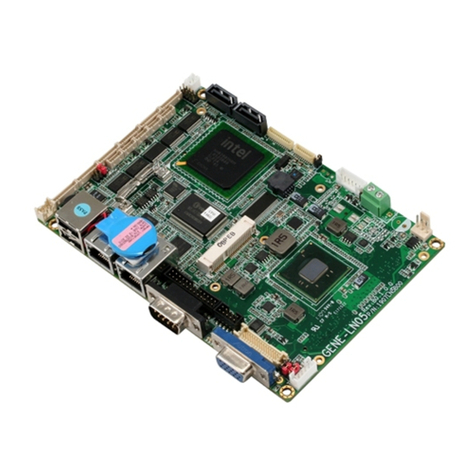
Aaeon GENE-1350 User manual

RISC CPU Module GENE-1350
GENE-1350
TI OMAP 3503/3530 Processor
RISC CPU Module
USB2.0 Host x 2 / USB2.0 Client x1
RS-232 x 1/ RS-23 2/485 x 1
TTL UART x 1
256MB NAND Flash, SD, MicroS D
GENE-1350 Rev.A Manual 1st Ed.
November 2010

RISC CPU Module GENE-1350
i
Copyright Notice
This document is copyrighted, 2010. All rights are reserved. The
original manufacturer reserves the right to make improvements
to the products described in this manual at any time without
notice.
No part of this manual may be reproduced, copied, translated,
or transmitted in any form or by any means without the prior
written permission of the original manufacturer. Information
provided in this manual is intended to be accurate and reliable.
However, the original manufacturer assumes no responsibility
for its use, or for any infringements upon the rights of third
parties that may result from its use.
We reserve the right to make changes in the product
design without notice to its users.

RISC CPU Module GENE-1350
ii
Acknowledgments
All other products’ name or trademarks are properties of their
respective owners.
z Award is a trademark of Award Software International, Inc.
z CompactFlash™ is a trademark of the Compact Flash
Association.
z Microsoft Windows® is a registered trademark of Microsoft Corp.
z ITE is a trademark of Integrated Technology Express, Inc.
z IBM, PC/AT, PS/2, and VGA are trademarks of International
Business Machines Corporation.
z SoundBlaster is a trademark of Creative Labs, Inc.
All other product names or trademarks are properties of their
respective owners.

RISC CPU Module GENE-1350
iii
Packing List
Before you begin installing your card, please make sure that the
following materials have been shipped:
• 1 GENE-13 50 CPU Module
• 1 CD-ROM for manual (in PDF format)
If any of these items should be missing or damaged, please
contact your distributor or sales representative immediately.

RISC CPU Module GENE-1350
iv
Contents
Chapter 1 General Information
1.1 Introduction............................................................ 1-2
1.2 Features ................................................................ 1-3
1.3 Specifications ........................................................ 1-4
Chapter 2 Quick Installation Guide
2.1 Safety P recautions................................................ 2-2
2.2 Location of Connect ors and Jumpers ................ 2-3
2.3 Mechanical Drawing .............................................2-5
2.4 List of Jumpers..................................................... 2-7
2.5 List of C onnectors ................................................ 2-7
2.6 Setting J umpers.................................................... 2-9
2.7 Reset Selection (JP1) .......................................... 2-10
2.8 COM2 V CC Selection (JP2)................................ 2-10
2.9 COM2 RS-232/422/485 Selection (JP3)............. 2-10
2.10 LVDS Backlight Voltage Selection (JP4) ......... 2-10
2.11 Right Audio Amplifie r Output Co nnector (CN1)2-10
2.12 Camera Module Co nnector (CN2) .................... 2-11
2.13 Keypad Connec tor (CN3) ..................................2-11
2.14 Digital I /O Connector (CN4) .............................. 2-11
2.15 Left Audio Amplifier Output Con nector (CN5) . 2-12
2.16 MIC/Line In / Line Out Connec tor (CN6) ........2-12
2.17 External DC IN 9~ 24V Connector (CN7)......... 2-12

RISC CPU Module GENE-1350
v
2.18 UART1 Port Con nector (CN8) .......................... 2-12
2.19 SIM Card Conne ctor (CN9)............................... 2-13
2.20 Mini Card 1 Co nnector (CN10)......................... 2-13
2.21 COM2 RS-232/422/485 Connector (CN11) ...... 2-14
2.22 Battery Connec tor (CN12) ................................. 2-14
2.23 Micro SD Conne ctor (CN13) .............................2-14
2.24 JTAG Connector (CN14) ...................................2-15
2.25 Touch Panel Connector (CN15)........................ 2-15
2.26 Backup Battery Co nnector (CN16) ...................2-15
2.27 Mini Card 2 Co nnector (CN17)......................... 2-15
2.28 TTL LCD Connec tor (CN18) .............................2-16
2.29 LVDS LCD Connector (CN19) .......................... 2-17
2.30 LCD Inverter C onnector (CN20) ....................... 2-18
2.31 Ethernet RJ -45 Connector (CN21).................... 2-18
2.32 USB Client Conn ector (CN23) ..........................2-19
2.33 COM1 RS-232 Con nector (CN25) .................... 2-19
2.34 D-SUB VGA Conn ector (CN26)........................2-19
2.35 SD Card Conn ector (CN27) .............................. 2-20
2.36 Proprietary Expansion 124-Pin Slot (CN28) ....2-20

RISC CPU Module GENE-1350
Chapter 1 General Information 1- 1
General
Chapter
1
Information

RISC CPU Module GENE-1350
1.1 Introduction
GENE-1350 adopts TI OMAP 3503/3530 Processor. This RISC CPU
module features low power consumption and cost -efficiency, to fu lfill
the requirements of hardy and more cost-focusing applications.
The module has 2COM ports (1 RS-232, 1 RS-23 2/485), 2 USB2.0
host, 1 USB 2.0 Client, Digital I/O , etc., to connect and co ntrol the
peripheral devices. Two Mini Card (with USB interface only) and one
Proprietary Expansion Slot make th e implementation of external
expansion. The CPU frequency is up t o 600 MHz and shows a better
performance. In addition, the GENE-1 350 companies with TI O MAP
3 Display Companion Chipset, the 3D Graphics & V ideo Accelerator
support with 3530 processor.
The power-saving co ntribution helps GENE-1350 to run rich
multimedia applications and perform excellently. For targeting at the
vehicle PC and mobile device markets, the GENE-1350 is no doubt the
best solution.
Chapter 1 General Information 1- 2

RISC CPU Module GENE-1350
1.2 Features
z TI OMAP 3503/3530 Processor
z 3D Graphics & Video Accelerator Support with 3530
Processor
z Onboard 128/256 MB (Optional) LP DDR RAM
z 10/100Base-TX Ethernet
z CRT/ 24-Bit TTL LCD/ 18-Bit LVDS LCD
z 2CH Audio
z Onoboard NAND Flash, SD, MicroSD
z USB2.0 Host x 2, USB2.0 Client x 1, COM x 2, 8-bit Digital
I/O
z Mini Card x 2, Proprietary Expansion Slot x 1
z +9V To +24V DC Input
z Onboard 4-Wire Resistive Touch Screen Controller
z Onboard Battery Charger
z Windows® CE 6.0/ Linux Kernal 2.6.32
z Less Than 3 Watts Power Consumption
Chapter 1 General Information 1- 3

RISC CPU Module GENE-1350
1.3 Specifications
System
• CPU TI OMAP 3503/3530 600 MHz
Processor
z System Memory Onboard 128/256MB
(Optional) LP DDR RAM
z Ethernet Davicom DM9000AEP,
10/100Base-TX, RJ-45 x 1
z Boot Loader Microsoft Windows CE or Linux
z Expansion Interface Mini Card (with USB interface
only) x 2, Proprietary Expansion
Slot x 1
z Watchdog Timer Generates a Time-out System
Reset
z Power Requirement +9V to +24V DC
z Battery Lithium battery
z Power Consumption TI OMAP 3530, 128MB LP DDR,
0.24A @ +12V
z Board Size 5.75”(L) x 4”(W) (146mm x
101.6mm)
z Gross Weight 0.88lb (0.4kg)
z Operating Temperature 32°F~158°F (0°C~70°C)
z Storage Temperature -40°F~176°F (-40°C~80°C)
z Operating Humidity 0%~90% relative humidity,
Chapter 1 General Information 1- 4

RISC CPU Module GENE-1350
non-condensing
z MTBF (Hours) 100,000
Display
z Chipset TI OMAP 3
z Resolution Up to 1280x768 for LCD
Up to 1024x768 for CRT
z LCD Interface Up to 24-bit single channel
TTL and 18-bit single channel
LVDS LCD
I/O
z Storage 256MB NAND Flash, SD,
MicroSD
z Serial Port RS-232 x 1, RS-232/422/485
(auto flow) x 1, TTL UART x 1
z Universal Serial Bus USB2.0 Host x 2, USB2.0 Client
x 1
z Digital I/O Supports 8-bit (Programmable)
z Audio Line-in, Line-out, Mic-in,
Speaker-out (1W amplifier)
z Touch Screen Supports 4-wire resistive touch
screen
z Keypad Interface Supports 6x6 matrix keypad
z Motion Sensor ST LIS35DE
Chapter 1 General Information 1- 5

RISC CPU Module GENE-1350
Chapter 2 Quick Installation Guide 2-1
Quick
Installation
Chapter
2
Guide

RISC CPU Module GENE-1350
Chapter 2 Quick Installation Guide 2 - 2
2.1 Safety Precautions
Always completely disconnect the power cord
from your board whenever you are working on
it. Do not make connections while the power is
on, because a sudden rush of power can
damage sensitive electronic components.
Always ground yourself to remove any static
charge before touching the board. Modern
electronic devices are very sensitive to static
electric charges. Use a grounding wrist strap at
all times. Place all electronic components on a
static-dissipative surface or in a static-shielded
bag when they are not in the chassis

RISC CPU Module GENE-1350
Chapter2QuickInstallationGuide
2 - 3
2.2 Location of Connectors and Jumpers
Component Side
CN18
CN2
CN20
CN8
CN12
CN7
CN3
CN6
CN5
CN1
JP1
JP2
CN11
CN9
JP3
CN14
CN10
CN16
JP4
CN26
USB1
CN17
CN25
CN21
CN23
CN28
CN4
CN13
CN19
CN15
MADE IN TAIWAN
P/N:1907135002
GENE-135 0 REV:A0.3
CN24
CN22

RISC CPU Module GENE-1350
Chapter 2 Quick Installation Guide 2 - 4
Solder Side
CN27

RISC CPU Module GENE-1350
Chapter2QuickInstallationGuide
2 - 5
2.3 Mechanical Drawing
Component Side
0.00
0.00
1.60
13.35
12.55
17.30
12.55
8.89
3.12
19.94
142.88
27.64
4.45
40.34
9.09
34.09
43.28
33.73
21.16
8.89
9.53
52.42
65.78
72.94
86.10
70.08
14.66
88.40
40.01
95.01
39.57
81.41
107.23
116.06
98.64
119.81
73.92
122.88
98.68
54.72
87.62
142.36
142.88
98.37
146.05
101.60
3.12
36.70
10.45
139.73
25.86
98.24
123.24
97.76
93.36
90.00
94.23
1.72
143.81
99.52 98.31
MADE IN TAIWAN
P/N:1907135002
GENE-1350 REV:A0.3
1.54
55.53
15.28
64.93
31.10
68.58
123.83
134.48
17.08
128.05
139.73
96.20
132.92
36.21
28.98
42.55
26.41

RISC CPU Module GENE-1350
Chapter 2 Quick Installation Guide 2 - 6
Solder Side
0.00
0.00
97.59
91.46
67.46
3.12
8.89
88.39
9.53
33.73
98.37
8.89
73.91
142.88
3.12
98.37
122.88
98.68

RISC CPU Module GENE-1350
Chapter2QuickInstallationGuide
2 - 7
2.4 List of Jumpers
The board has a number of jumpers that allow you to configure your
system to suit your application.
The table below shows the function of each of the board's jumpers:
Label Function
JP1 Reset Selection
JP2 COM2 VCC Selection
JP3 COM2 RS-232/422/485 Selection
JP4 LVDS Backlight Voltage Selection
2.5 List of Connectors
The board has a number of connectors that allow you to configure your
system to suit your application.
The table below shows the function of each of the board's connectors:
Label Function
CN1 Right audio amplifier output Connector
CN2 Camera Module Connector
CN3 Keypad Connector
CN4 Digital I/O Connector
CN5 Left Audio Amplifier Output Connector
CN6 MIC/LINE IN/LINE OUT Connector
CN7 External DC IN 9~24V Connector
CN8 UART1 Port Connector
CN9 SIM Card Connector
CN10 Mini Card 1 Connector

RISC CPU Module GENE-1350
Chapter 2 Quick Installation Guide 2 - 8
CN11 COM2 RS232/422/485 Connector
CN12 Battery Connector
CN13 Micro SD Connector
CN14 JTAG Connector
CN15 Touch Panel Connector
CN16 Backup Battery Connector
CN17 Mini Card 2 Connector
CN18 TTL LCD Connector
CN19 LVDS LCD Connector
CN20 LCD Inverter Connector
CN21 Ethernet RJ-45 Connector
CN23 USB Client Connector
CN25 COM1 RS-232 Connector
CN26 D-SUB VGA Connector
CN27 SD Card Connector
CN28 Proprietary Expansion 124-Pin Slot
Note: CN2 is parallel interface, which supports two modes:
SYNC mode: In this mode, the image-sensor module provides horizontal and
vertical synchronization signals to the parallel interface, along with the pixel
clock. This mode works with 8-, 10-, 11-, and 12-bit data (above 10-bit RAW
data, the processing pipe cannot be used; data must
be transferred to memory). SYNC mode supports progressive and interlaced
image-sensor modules.
ITU mode: In this mode, the image-sensor module provides an ITU-R BT
656-compatible data stream. The horizontal and vertical synchronization
signals are not provided to the interface. Instead, the data stream embeds
start-of-active (SAV) and end-of-active video (EAV) synchronization code. This
mode works in 8- and 10-bit configurations. It supports only progressive
image-sensor modules.

RISC CPU Module GENE-1350
Chapter2QuickInstallationGuide
2 - 9
2.6 Setting Jumpers
You configure your card to match the needs of your application by
setting jumpers. A jumper is the simplest kind of electric switch. It
consists of two metal pins and a small metal clip (often protected by a
plastic cover) that slides over the pins to connect them. To “close” a
jumper you connect the pins with the clip.
To “open” a jumper you remove the clip. Sometimes a jumper will have
three pins, labeled 1, 2 and 3. In this case you would connect either
pins 1 and 2 or 2 and 3.
123
Open Closed Closed 2-3
A pair of needle-nose pliers may be helpful when working with jumpers.
If you have any doubts about the best hardware configuration for your
application, contact your local distributor or sales representative before
you make any change.
Generally, you simply need a standard cable to make most
connections.
Table of contents
Other Aaeon Motherboard manuals

Aaeon
Aaeon GENE-5315 User manual

Aaeon
Aaeon EMB-LN9T Rev.B User manual

Aaeon
Aaeon PCM-6894 User manual

Aaeon
Aaeon PCM-5894 User manual

Aaeon
Aaeon MIX-Q370D2 User manual

Aaeon
Aaeon EMB-Q87B User manual

Aaeon
Aaeon SBC-557 User manual

Aaeon
Aaeon COM-45GS User manual

Aaeon
Aaeon GENE-A55E User manual

Aaeon
Aaeon EMB-945T User manual

Aaeon
Aaeon GENE-HD05 User manual

Aaeon
Aaeon IMBM-B75A User manual

Aaeon
Aaeon EPC-CV1 Series User manual

Aaeon
Aaeon PICO-BT01 User manual

Aaeon
Aaeon GENE-9455 Rev.B User manual

Aaeon
Aaeon EMB-Q87A User manual

Aaeon
Aaeon PCM-6890B User manual

Aaeon
Aaeon ?COM-BT User manual

Aaeon
Aaeon EMB-APL3 User manual

Aaeon
Aaeon SBC-410 User manual