ABB A100-M Series User manual

Turbocharger / A100-M radial
Original assembly instructions – English
This document is valid for the
A100-M series:
A170-M, A175-M
Purpose
The assembly instructions explain how the ABB
turbocharger is fitted to the engine correctly and
without any health and safety risks.
Target group
The assembly instructions are intended for
engineers and mechanics responsible for fitting
the turbocharger on the engine.
A100-M turbocharger
More power, more options
—
ASSEMBLY INSTRUCTIONS
Turbocharger / A100-M axial
Original assembly instructions – English


Assembly Instructions / A170-M, A175-M
Table of contents
© Copyright 2020 ABB. All rights reserved. HZTL455311P0007_EN Rev.A July 2020
Assembly Instructions
1 Introduction............................................................................................................ 2
1.1 Purpose of the assembly instructions....................................................................... 2
1.2 Definition of target group ........................................................................................... 2
1.3 Symbols, definitions...................................................................................................... 2
1.4 Definition of warning, caution, note.......................................................................... 3
1.5 Definition of mandatory signs ................................................................................... 4
2 Safety ...................................................................................................................... 5
2.1 Introduction .................................................................................................................... 5
2.2 Lifting of loads .............................................................................................................. 6
2.3 Occupational safety ...................................................................................................... 7
3 Weight and transportation of the turbocharger ............................................... 9
4 Installing the turbocharger................................................................................. 10
4.1 Tightening the clamping nut ..................................................................................... 14
5 Storage of new turbochargers and spare parts .............................................. 16
6 Further information............................................................................................. 20

Assembly Instructions / A170-M, A175-M
1 Introduction / 1.1 Purpose of the assembly instructions
© Copyright 2020 ABB. All rights reserved. HZTL455311P0007_EN Rev.A July 2020
1 Introduction
1.1 Purpose of the assembly instructions
The assembly instructions explain how the ABB turbocharger is fitted to the engine correctly
and without any health and safety risks. This element of the documentation is supplied with
the product, as is required for partly completed machinery in accordance with machinery dir-
ective 2006/42EC.
The assembly instructions are a complement to and expansion of existing national regula-
tions for occupational safety, accident prevention and environmental protection.
1.2 Definition of target group
The assembly instructions are intended for engineers and mechanics responsible for fitting
the turbocharger on the engine. Basic mechanical training is a prerequisite.
All persons who are involved in the transportation and installation of the turbocharger have
read and understood the assembly instructions.
1.3 Symbols, definitions
Symbols
The following symbols are used in this document:
uIndicates an action step.
1. Indicates a numbered action step.
¡Indicates a list.
[➙ ] Refers to a page number
The trademarks of outside companies are used in this document. These are marked with the
® symbol.
Design variants
This document is valid for different design variants of turbochargers. There may be sections
and descriptions of components that are not relevant for a specific turbocharger variant.
ABB Turbocharging Service Stations will be happy to provide information about questions
regarding a design variant (see "Contact Information" on our website www.abb.com/tur-
bocharging).
Accuracy of illustrations
The illustrations in this document are general in nature and intended for ease of understand-
ing. Differences in detail are therefore possible.
Page 2 / 21

Assembly Instructions / A170-M, A175-M
1 Introduction / 1.4 Definition of warning, caution, note
© Copyright 2020 ABB. All rights reserved. HZTL455311P0007_EN Rev.A July 2020
ABB Turbocharging
ABB Switzerland Ltd, Turbocharging is identified as ABB Turbocharging in this document.
Official service stations of ABB Turbocharging
Official service stations are regularly audited and certified by ABB Turbocharging. See "Con-
tact Information" on our website at www.abb.com/turbocharging.
1.4 Definition of warning, caution, note
WARNING
Definition of Warning
Non-compliance or inaccurate compliance with working or operating in-
structions indicated by this symbol and the word WARNING can lead to seri-
ous injuries to personnel and even to fatal accidents.
uWarning signs must always be observed.
CAUTION
Definition of Caution
Non-compliance or inaccurate compliance with working or operating in-
structions indicated by this symbol and the word CAUTION can lead to seri-
ous damage to engine or property with grave consequences.
uCaution signs must always be observed.
NOTICE
Note
The note provides advice which facilitates the work.
Page 3 / 21

Assembly Instructions / A170-M, A175-M
1 Introduction / 1.5 Definition of mandatory signs
© Copyright 2020 ABB. All rights reserved. HZTL455311P0007_EN Rev.A July 2020
1.5 Definition of mandatory signs
To be worn at all times
Protective clothing Safety footwear to protect
against mechanical hazard and
risk of falling
Table1: Personal protective equipment to be worn at all times
To be worn specific to the respective task
Safety glasses Safety goggles
Safety gloves to protect
against
- Mechanical hazard
- Chemical hazard
- Thermal hazard
Respiratory mask to protect
against
- Dusts
- Gases
Safety helmet Ear protection
Table2: Personal protective equipment to be worn specific to the respective task
Definition of pictograms
The following pictograms can occur in this document. These point out actions that must be
taken in accordance with the meaning of the relevant pictogram.
Pictogram Meaning Pictogram Meaning
Tighten with specified torque Affix
Tighten over specified tight-
ening angle
Measure
Hand-tight, tighten without
tools
Note
Oil Visually inspect
Apply screw locking paste
(e.g. Loctite)
Please note text for numbered
work step.
Apply high-temperature
grease
See document
Apply other paste in accord-
ance with specifications
Dispose of in an environmentally
compatible, professional way
and in compliance with locally
applicable regulations.
Oil free, grease free and dry
Table3: Definition of pictograms
Page 4 / 21

Assembly Instructions / A170-M, A175-M
2 Safety / 2.1 Introduction
© Copyright 2020 ABB. All rights reserved. HZTL455311P0007_EN Rev.A July 2020
2 Safety
2.1 Introduction
State of the art
Turbochargers manufactured by ABB Turbocharging are state of the art and comply with the
respective health and safety standards in effect at the time the turbocharger was built. This
ensures safe operation of the turbocharger.
CE conformity information
ABB turbochargers comply with the Machinery Directive 2006/42/EC and are partly com-
pleted machinery as defined by Article 2 g.
Residual risks
Nevertheless, there may be some residual risks during operation of and work on the tur-
bocharger which:
¡are caused by the turbocharger itself or its accessories.
¡are caused by the operating equipment used or supplies and materials.
¡are a consequence of insufficient compliance with safety instructions.
All of the instructions contained within this chapter must be followed when working on the
turbocharger.
Responsibility of the operating company
In awareness of its responsibility, the operating company must ensure that only authorised
personnel work on the turbocharger, who:
¡Correspond to the target group (see Definition of target group →2).
¡Are versed in the general and locally applicable regulations for occupational safety and
accident prevention
¡Are equipped with the prescribed personal protective equipment
¡Have been instructed in the use of the turbocharger.
The safety-conscious work of the personnel and adherence to the assembly instructions
must be checked periodically.
Suitable working materials and personal protective equipment must be kept in a perfect
condition.
Page 5 / 21

Assembly Instructions / A170-M, A175-M
2 Safety / 2.2 Lifting of loads
© Copyright 2020 ABB. All rights reserved. HZTL455311P0007_EN Rev.A July 2020
2.2 Lifting of loads
WARNING
Suspended loads
Loads that are not attached according to regulations can cause injury to
personnel or fatal accidents.
uLoads must always be fastened to properly functional lifting gear with a
sufficient load limit.
uPay attention to the correct attachment of loads on the crane hook.
uPeople must not stand beneath suspended loads.
Wear safety gloves to protect against mechanical hazards.
Wear safety helmet.
Fig.1: Attachment of loads on the crane hook
Fig.2: Attachment angle
If there are two or more suspension points, the attachment angle of 45° must not be ex-
ceeded. This prevents excessive loading due to diagonal pull.
uUse a suitable edge guard if there are sharp edges.
uThe assembly devices must be completely screwed in and must not unscrew during use.
uUse assembly devices only for the described applications.
Page 6 / 21

Assembly Instructions / A170-M, A175-M
2 Safety / 2.3 Occupational safety
© Copyright 2020 ABB. All rights reserved. HZTL455311P0007_EN Rev.A July 2020
2.3 Occupational safety
General
WARNING
Injuries to persons
Severe injuries to personnel or fatal accidents can be caused by mechanical
influences as a consequence of hazardous and inadequate operational pro-
cedures or non-compliance with safety and health standards.
uWhen working on the turbocharger always wear safety footwear and pro-
tective clothing to protect against mechanical hazards.
uKeep personal protective equipment in perfect condition.
uObey mandatory signs.
uObserve the general rules for occupational safety and prevention of acci-
dents.
uOnly perform operations that are described in this document.
uOnly perform operations for which you have received instruction or train-
ing.
Wear safety footwear to protect against mechanical hazard and risk of fall-
ing.
Wear protective clothing.
WARNING
Risk of falling
When working on the turbocharger, there is a risk of falling.
uDo not climb onto the turbocharger or onto attached parts and do not
use them as climbing aids.
uUse suitable climbing aids and working platforms for work above body
height.
uOnly perform work on the turbocharger when you are in a physically and psychologically
stable condition.
uOnly work with suitable tools, equipment and appliances that function properly.
uKeep the workplace clean; clear away any loose objects and obstacles on the floor.
uKeep the floor, equipment, and turbocharger clean.
uHave oil binding agents ready and provide or keep oil pans at hand.
Welding work in the vicinity of the turbocharger
uWhen performing welding work in the vicinity of the turbocharger, always cover the filter
silencer to prevent the filter mat from being damaged.
Page 7 / 21

Assembly Instructions / A170-M, A175-M
2 Safety / 2.3 Occupational safety
© Copyright 2020 ABB. All rights reserved. HZTL455311P0007_EN Rev.A July 2020
uKeep flammable objects and substances out of the vicinity of flying sparks.
uCover all connections on the turbocharger so that no foreign objects can enter the tur-
bocharger.
uWear personal protective equipment (PPE) for welding operations.
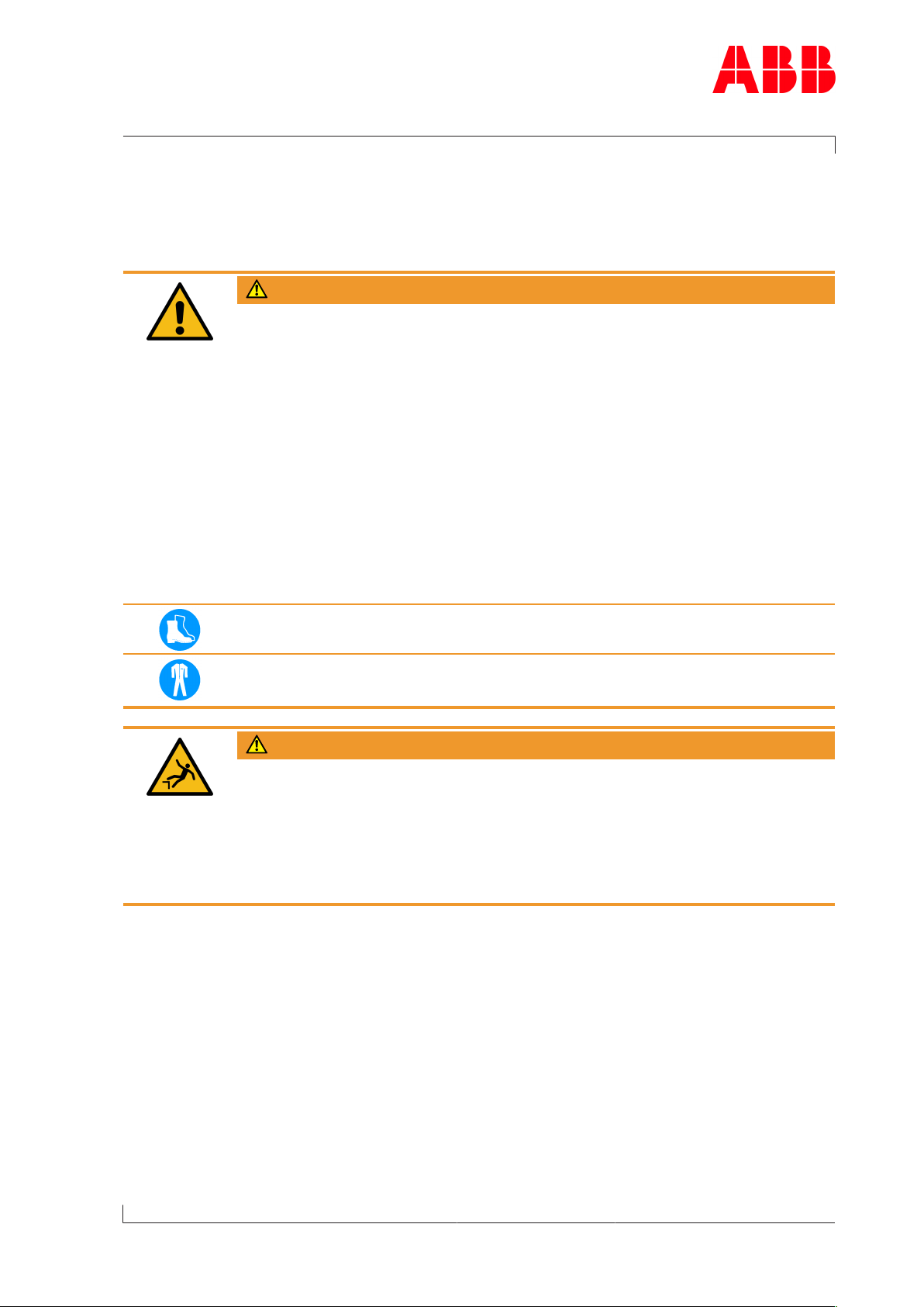
Mechanical hazards when working on the turbocharger
WARNING
Mechanical hazard
Severe injuries to personnel or fatal accidents can be caused by mechanical
influences as a consequence of hazardous and inadequate operational pro-
cedures.
uObserve the general rules for occupational safety and prevention of acci-
dents.
uEnsure workplace safety.
uOnly perform operations that are described in this chapter.
uOnly perform operations for which you have previously received instruc-
tion or training.
Hazards due to operating materials and supplies
Operating materials and supplies can include: Oils, greases, coolants, cleaning agents and
solvents, acids or similar substances.
WARNING
Handling operating materials and supplies
Swallowing or inhaling vapours of operating materials and supplies or con-
tact with them may be harmful to health. Flammable and combustible oper-
ating materials and supplies can catch fire or resulting vapours can lead to
an explosion.
uDo not breathe in these substances and avoid contact with the skin.
uEnsure proper ventilation.
uObserve the information in the material safety data sheet for the operat-
ing materials and supplies.
uComply with local legislation.
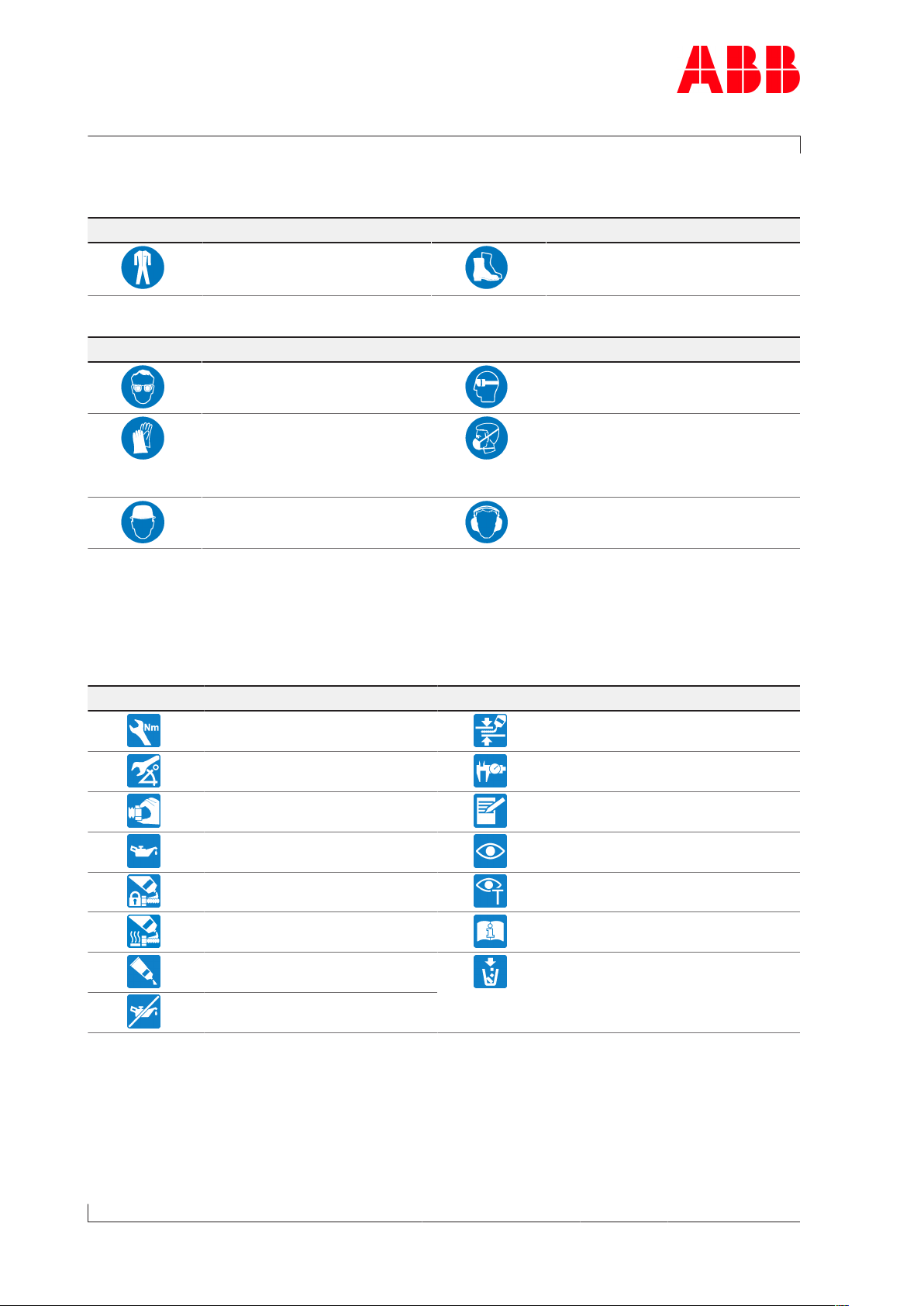
Wear safety goggles.
Wear safety gloves to protect against mechanical hazards.
Wear a respiratory mask to protect against gases.
Page 8 / 21

Assembly Instructions / A170-M, A175-M
3 Weight and transportation of the turbocharger /
© Copyright 2020 ABB. All rights reserved. HZTL455311P0007_EN Rev.A July 2020
3 Weight and transportation of the
turbocharger
Lifting gear with a sufficient load limit must be used for transporting the turbocharger. The
weight specified below applies to the heaviest variant possible. Depending on the specifica-
tion, the weight specified on the rating plate may be lower than the standard value specified
here.
Fig.3: Turbocharger suspension points
Weight of the entire turbocharger
Product Weight [kg]
A170-M 3100
A175-M 4600
Table4: Weight of the turbocharger
Page 9 / 21

Assembly Instructions / A170-M, A175-M
4 Installing the turbocharger /
© Copyright 2020 ABB. All rights reserved. HZTL455311P0007_EN Rev.A July 2020
4 Installing the turbocharger
WARNING
Risk of tipping
If the turbocharger is not sufficiently supported or not supported at all dur-
ing removal and installation, it may tip over and cause severe injury to per-
sonnel or accidents resulting in fatalities.
uSupport the turbocharger at a suitable location.
uSecure with lifting gear wherever possible.
Fig.4: Turbocharger suspension points
uIf present: Remove insulation segment on the bearing casing.
uAttach lifting gear to the suspension lug of the bearing casing and the turbine-end foot.
uRemove the covers from the oil connections.
uAlign turbocharger and place on bracket.
Page 10 / 21

Assembly Instructions / A170-M, A175-M
4 Installing the turbocharger /
© Copyright 2020 ABB. All rights reserved. HZTL455311P0007_EN Rev.A July 2020
Removing auxiliary screws
Fig.5: Removing auxiliary screw
uRemove shipping screws (90334 / 90335) on the left and right side of the foot and place
in the toolbox.
The turbocharger is delivered with a pre-installed sliding block (68003). The shipping screws
secure the sliding block in the preset position. In operation, the foot can slip due to thermal
expansion.
uTighten clamping nuts as described in the following sections.
uConnect all gas, air and oil pipes.
uIf present: Re-fit the insulation segments.
uIf present: Connect cable to speed sensor.
Compressor-end (CE) foot
Fig.6: Compressor-end foot
Page 11 / 21

Assembly Instructions / A170-M, A175-M
4 Installing the turbocharger /
© Copyright 2020 ABB. All rights reserved. HZTL455311P0007_EN Rev.A July 2020
Turbine-end (TE) foot
Fig.7: Turbine-end foot
Product Foot screw dimension
[mm]
Strength class
A170-M M30 10.9
A175-M M36 10.9
Table5: Foot screws, dimension and strength class
Product Dimension CE [mm]
a1 b1 c1
A170-M 82 ø32x23 68
A175-M 95 ø38x31 85
Table6: Foot screws, dimension CE
Product Dimension TE [mm]
a2 / a3 b2 c2 / c3
A170-M 94 / 124 ø32x11 56 / 45
A175-M 113 / 148 ø38x12 66 / 54
Table7: Foot screws, dimension TE
Product Number of cup springs X
A170-M 9
A175-M 11
Table8: Foot screws, number of cup springs
Holes b1/b2 are needed to achieve the required clamping length. An additional drill hole is
not needed at the higher turbine-end foot side (01).
Page 12 / 21

Assembly Instructions / A170-M, A175-M
4 Installing the turbocharger /
© Copyright 2020 ABB. All rights reserved. HZTL455311P0007_EN Rev.A July 2020
Fixing clamping nuts
Fig.8: CE foot contact surface
uTighten clamping nuts on compressor end (CE) (see Tightening the clamping nut).
Fig.9: TE foot: Handling of cup spring contact surface / foot contact surface
uGrease the contact surface (F) for the cup springs (X) (see Table5: Foot screws, dimen-
sion and strength class →12) on the foot of the turbine end (TE) with high-temperature
grease.
uTighten clamping nuts on turbine end (TE) (see Tightening the clamping nut).
Page 13 / 21

Assembly Instructions / A170-M, A175-M
4 Installing the turbocharger / 4.1 Tightening the clamping nut
© Copyright 2020 ABB. All rights reserved. HZTL455311P0007_EN Rev.A July 2020
4.1 Tightening the clamping nut
Preparation for tightening
CAUTION
Do not clean pressure screws (d)
The pressure screws are equipped with a permanent sliding layer that must
not be removed.
Do neither clean nor lubricate the pressure screws. In case of non-compli-
ance, it cannot be ensured that the necessary tension force is reached.
uDo not clean pressure screws.
uDo not lubricate pressure screws.
NOTICE
Pressure screws (d) must not protrude from the clamping nut (c) in the dir-
ection of the thrust washer (b)
In order to correctly fit the clamping nuts, the pressure screws must not
protrude in the direction of the thrust washer.
Fig.10: Tightening the foot screws (1)
1. Clean the bolt thread (a) and the contact surface.
Coat the bolt thread with grease.
2. Fit thrust washer (b) (component of clamping nut).
3. Tighten clamping nut (c) by hand.
4. Screw back clamping nut by ¼ of a turn (90°).
The distance between the thrust washer and the clamping nut is now about 1 mm.
Page 14 / 21

Assembly Instructions / A170-M, A175-M
4 Installing the turbocharger / 4.1 Tightening the clamping nut
© Copyright 2020 ABB. All rights reserved. HZTL455311P0007_EN Rev.A July 2020
Tightening procedure
Fig.11: Tightening procedure
Product Fixing screw [mm] Tightening torques [Nm]
A170-M M30 45
A175-M M36 85
Table9: Torque-controlled tightening of the pressure screws
1. Screw in pressure screws crosswise by hand until reaching the stop.
2. Tighten pressure screws crosswise to 50% of the tightening torque specified in the
table.
3. Tighten pressure screws crosswise to 100% of the tightening torque specified in the
table.
4. Work in a circle to tighten all pressure screws to 100% of the tightening torque specified
in the table.
5. Tighten pressure screws to 100% in 5…7 rounds until the required residual tightening
angle of <20° is achieved.
Page 15 / 21

Assembly Instructions / A170-M, A175-M
5 Storage of new turbochargers and spare parts /
© Copyright 2020 ABB. All rights reserved. HZTL455311P0007_EN Rev.A July 2020
5 Storage of new turbochargers and
spare parts
Storage of new turbochargers and spare parts up to 6 months
New turbochargers and spare parts can be stored in sealed packaging without additional
mothballing measures for up to 6months from the date of delivery (marked by the VCI label
on the package).
Fig.12: Volatile Corrosion Inhibitor (VCI)
Only dry rooms in which the relative humidity is between 40…70 % and no condensation can
form are suitable for storage.
Storage of new turbochargers and spare parts for more than 6 months
WARNING
Protection of health when handling VCIs
VCI products are not hazardous in the sense of the Hazardous Substances
Ordinance. Nevertheless, the following points are to be observed when
handling VCIs:
uObserve specifications in the safety data sheet
uEnsure good room ventilation.
uDo not eat, drink or keep food at the workplace while working with VCIs.
uClean hands and face after working with VCIs.
uFor further information refer to www.branopac.com.
Wear safety gloves to protect against mechanical hazards.
The following mothballing measures are required every 6months:
uOpen the package.
uRemove the VCI corrosion protection emitter from the package and replace it with a new,
identical VCI corrosion protection emitter. New VCI corrosion protection emitters can be
obtained at www.branopac.com.
uDispose of the old VCI corrosion protection emitter in an environmentally compatible
manner, professionally and in accordance with local regulations.
uSeal the package. The better the external seal is designed, the more permanent the pro-
tection.
Page 16 / 21

Assembly Instructions / A170-M, A175-M
5 Storage of new turbochargers and spare parts /
© Copyright 2020 ABB. All rights reserved. HZTL455311P0007_EN Rev.A July 2020
Long-term storage of turbochargers
The turbochargers will be prepared for prolonged storage by ABB Turbocharging on re-
quest. The package is equipped with a hygrometer (see illustration).
Fig.13: Package with hygrometer
The following measures are required every 6months:
uCheck the hygrometer(02) in the sight-glass. There is an opening(01) in the wooden
crate which allows this check to be carried out. When the display field has changed colour
at the 70% level, the maximum permissible humidity has been exceeded. In this case the
turbocharger must be inspected by an ABB Turbocharging Service Station and repacked.
uInspect the package for damage. If the package is damaged, the turbocharger must be in-
spected by an ABB Turbocharging Service Station and repacked.
After every 3 years the following work steps must be performed by an ABB Turbocharging
Service Station:
¡Inspect the components
¡Replace the desiccant agent
¡Repackage the components.
If the 70% display field of the hygrometer(02) has not changed colour and the package is
undamaged, the turbocharger can be placed into operation without any prior testing by an
ABB Turbocharging Service Station.
Unpacking turbochargers
The corrosion protection effect ends after the material is unpacked from the VCI package.
To avoid the formation of condensation, the surroundings and the content of the package
must have the same temperature during unpacking.
Page 17 / 21

Assembly Instructions / A170-M, A175-M
5 Storage of new turbochargers and spare parts /
© Copyright 2020 ABB. All rights reserved. HZTL455311P0007_EN Rev.A July 2020
Page 18 / 21
Other manuals for A100-M Series
1
This manual suits for next models
2
Table of contents
Other ABB Batteries Charger manuals
Popular Batteries Charger manuals by other brands

IKEA
IKEA NORDMÄRKE manual

Chargetek
Chargetek RTIC 2405-WP installation manual

Parkside
Parkside 351747 2007 instructions

Ocean Technology Systems
Ocean Technology Systems RCS-15 Operation instructions

SIGOR
SIGOR Nuindie Instructions for use

Applied Energy
Applied Energy STEED Installation and operating instructions