ABB i-bus KNX MG/S 11.100.1.1 User manual

—
PRODUCT MANUAL
ABB i-bus® KNX
MG/S 11.100.1.1
Modbus RTU – KNX TP Gateway


ABB i-bus®KNX
Content
Note about navigation in the PDF: Key combination MG/S 11.100.1.1 | 9AKK108467A5941 EN Rev. Bi
'Alt + left arrow' jumps to the previous view/page
Content
Page
— i
ABB i-bus® KNX ................................................................................................ i
1General ................................................................................................. 3
1.1 Using the product manual............................................................................................................ 3
1.2 Legal disclaimer........................................................................................................................... 3
1.3 Explanation of symbols................................................................................................................ 3
1.4 2D code ....................................................................................................................................... 5
2Safety .................................................................................................... 6
2.1 General safety instructions .......................................................................................................... 6
2.2 Qualification of the specialist personnel ...................................................................................... 6
2.3 Proper use ................................................................................................................................... 6
3Product overview................................................................................. 7
3.1 Device description ....................................................................................................................... 7
3.2 Product name description............................................................................................................ 7
3.3 Ordering details ........................................................................................................................... 7
3.4 Connections................................................................................................................................. 8
3.4.1 Inputs........................................................................................................................................... 8
3.4.2 Outputs........................................................................................................................................ 8
3.5 MG/S 11.100.1.1 Modbus RTU – KNX TP Gateway, 100 Points................................................. 9
3.5.1 Dimension drawing .....................................................................................................................10
3.5.2 Connection diagram ...................................................................................................................11
3.5.3 Operating controls and display elements....................................................................................12
3.5.4 Technical data ............................................................................................................................13
3.5.4.1 General technical data................................................................................................................13
3.5.5 Device type – KNX interface.......................................................................................................14
3.5.6 Device type – Modbus interface .................................................................................................14
4Function.............................................................................................. 15
4.1 Device functions .........................................................................................................................15
4.2 Software functions ......................................................................................................................15
4.2.1 Device Configuration App (DCA) ................................................................................................16
4.3 Special operating states .............................................................................................................16
4.3.1 Reaction on bus voltage failure ..................................................................................................16
4.3.2 Reaction after bus voltage recovery ...........................................................................................17
4.3.3 Reaction on ETS reset ...............................................................................................................17
4.3.4 Reaction during download ..........................................................................................................17
5Mounting and installation ................................................................. 19
5.1 Information about mounting........................................................................................................19
5.2 Mounting on mounting rail ..........................................................................................................20

ABB i-bus®KNX
Content
ii 9AKK108467A5941 Rev. B | MG/S 11.100.1.1 | EN | Product Manual Note about navigation in the PDF: Key combination
'Alt + left arrow' jumps to the previous view/page
6Commissioning ..................................................................................21
6.1 Prerequisites for commissioning ................................................................................................ 21
6.2 Commissioning overview ........................................................................................................... 21
6.3 Putting the device into operation................................................................................................ 21
6.4 Assignment of the physical address........................................................................................... 22
6.5 Software/application................................................................................................................... 22
6.5.1 Download reaction ..................................................................................................................... 22
6.5.2 Copying, exchanging and converting......................................................................................... 22
6.6 Device Configuration App (DCA) ............................................................................................... 23
6.6.1 Export Device Templates........................................................................................................... 24
6.6.2 Import Device Templates........................................................................................................... 24
6.6.3 Edit Devices............................................................................................................................... 26
6.6.4 Firmware Updates ..................................................................................................................... 27
7Parameters..........................................................................................29
7.1 General...................................................................................................................................... 29
7.2 Parameter windows ................................................................................................................... 30
7.2.1 General parameter window........................................................................................................ 30
7.2.1.1 Read On Init Delay .................................................................................................................... 31
7.2.1.2 Time Telegram Rate .................................................................................................................. 31
7.2.1.3 In Operation ............................................................................................................................... 32
7.2.1.4 Sending cycle ............................................................................................................................ 32
7.2.1.5 Baud rate ................................................................................................................................... 33
7.2.1.6 Data Type .................................................................................................................................. 33
7.2.1.7 Response Timeout..................................................................................................................... 34
7.2.1.8 Interframe Timeout .................................................................................................................... 34
7.2.1.9 Poll After Write........................................................................................................................... 35
7.2.1.10 Number of Devices .................................................................................................................... 35
7.2.1.11 Device x Name .......................................................................................................................... 36
7.2.1.12 Device x Server Address ........................................................................................................... 37
7.2.1.13 Device x Number of Data Points................................................................................................ 38
7.2.1.14 Device x Active .......................................................................................................................... 39
7.2.2 Config Device x parameter window ........................................................................................... 40
7.2.2.1 Device x Name .......................................................................................................................... 41
7.2.2.2 Device x Server Address ........................................................................................................... 42
7.2.2.3 Device x Number of Data Points................................................................................................ 43
7.2.2.4 Device x Active .......................................................................................................................... 44
7.2.2.5 "Device x Active" checkbox........................................................................................................ 45
7.2.2.6 Group Object name ................................................................................................................... 45
7.2.2.7 DPT............................................................................................................................................ 46
7.2.2.8 Read Function ........................................................................................................................... 46
7.2.2.9 Write Function............................................................................................................................ 47
7.2.2.10 Data Length ............................................................................................................................... 47
7.2.2.11 Format ....................................................................................................................................... 48
7.2.2.12 Byte Order ................................................................................................................................. 48
7.2.2.13 Register Address ....................................................................................................................... 49
7.2.2.14 Bit .............................................................................................................................................. 49
7.2.2.15 # Bits.......................................................................................................................................... 50
7.2.2.16 Deadband .................................................................................................................................. 50
7.2.2.17 Operation ................................................................................................................................... 51
7.2.2.18 Operation Value......................................................................................................................... 51

ABB i-bus®KNX
Content
Note about navigation in the PDF: Key combination MG/S 11.100.1.1 | 9AKK108467A5941 EN Rev. Biii
'Alt + left arrow' jumps to the previous view/page
8Group Objects.................................................................................... 53
8.1 Overview of Group Objects.........................................................................................................53
8.2 KNX Status Group Objects.........................................................................................................54
8.3 Dx.x Control Group Objects........................................................................................................55
8.4 Dx.x Status Group Objects .........................................................................................................55
9Operation............................................................................................ 57
9.1 Manual operation........................................................................................................................57
10 Maintenance and cleaning ................................................................ 59
10.1 Maintenance ...............................................................................................................................59
10.2 Cleaning .....................................................................................................................................59
11 Removal and disposal ....................................................................... 61
11.1 Removal .....................................................................................................................................61
11.2 Environment ...............................................................................................................................62
12 Planning and application .................................................................. 63
12.1 Priorities......................................................................................................................................63
12.2 Basic knowledge.........................................................................................................................63
12.2.1 General Modbus RTU/RS-485 information.................................................................................63
12.2.2 What is Modbus?........................................................................................................................63
12.2.3 Bus principle RS-485..................................................................................................................63
12.2.4 Polarity........................................................................................................................................64
12.2.5 Topology.....................................................................................................................................64
12.2.6 Cable types.................................................................................................................................64
12.2.7 Cable length ...............................................................................................................................64
12.2.8 Number of devices......................................................................................................................64
12.2.9 Troubleshooting..........................................................................................................................65
13 Appendix ............................................................................................ 67
13.1 Scope of delivery ........................................................................................................................67
13.2 Status byte Device......................................................................................................................68


ABB i-bus®KNX
General
Note about navigation in the PDF: Key combination Product Manual | EN | MG/S 11.100.1.1 | 9AKK108467A5941 Rev. B3
'Alt + left arrow' jumps to the previous view/page
1 General
1.1 Using the product manual
This manual provides detailed technical information on the function, installation and programming of the
ABB i-bus®KNX device.
1.2 Legal disclaimer
ABB AG reserves the right to make changes to the product or modify the contents of this document without
prior notice.
The agreed properties are definitive for any orders placed. ABB AG does not accept any responsibility
whatsoever for potential errors or possible lack of information in this document.
ABB AG reserves all rights in this document and in the subject matter and illustrations contained therein.
Reproduction, transfer to third parties or processing of the content – including sections thereof – is not
permitted without the prior written consent of ABB AG.
Copyright © 2023 ABB AG
All rights reserved
1.3 Explanation of symbols
1.
Instructions in specified sequence and result
2.
►Individual actions
a) Priorities
1) Processes run by the device in a specific sequence
•List level 1
- List level 2
Table 1: Explanation of symbols

ABB i-bus®KNX
General
49AKK108467A5941 Rev. B | MG/S 11.100.1.1 | EN | Product Manual Note about navigation in the PDF: Key combination
'Alt + left arrow' jumps to the previous view/page
Notes and warnings are represented as follows in this manual:
DANGER
This symbol is a warning about electrical voltage and indicates high-risk hazards that will definitely result
in death or serious injury unless avoided.
DANGER
Indicates high-risk hazards that will definitely result in death or serious injury unless avoided.
WARNING
Indicates medium-risk hazards that could result in death or serious injury unless avoided.
CAUTION
Indicates low-risk hazards that could result in slight or moderate injury unless avoided.
CAUTION
Indicates a risk of malfunctions or damage to property and equipment, but with no risk to life and limb.
Example
For use in application, installation and programming examples
Note
For use in tips on use and operation

ABB i-bus®KNX
General
Note about navigation in the PDF: Key combination Product Manual | EN | MG/S 11.100.1.1 | 9AKK108467A5941 Rev. B5
'Alt + left arrow' jumps to the previous view/page
1.4 2D code
The packaging and the front of the device are labeled with a 2D code. These codes are used for unique
identification of the device and include the following information:
•Link to the product page
•Order code
•Device serial number
The 2D codes can be read using any mobile device with an appropriate 2D code reader.
By scanning the 2D codes with the ABB Product Scanner, you can open additional digital services.

ABB i-bus®KNX
Safety
69AKK108467A5941 Rev. B | MG/S 11.100.1.1 | EN | Product Manual Note about navigation in the PDF: Key combination
'Alt + left arrow' jumps to the previous view/page
2 Safety
2.1 General safety instructions
▶Protect the device from moisture, dirt and damage during transport, storage and operation.
▶Only operate the device in an enclosed housing (distribution board).
▶Do not operate the device outside the specified technical data.
▶Mounting, installation, commissioning and maintenance must be carried out exclusively by qualified
electricians.
▶Disconnect the device from the electrical power supply before mounting.
2.2 Qualification of the specialist personnel
Programming the device requires detailed specialist knowledge of Modbus and KNX – particularly about
the ETS commissioning software – acquired through KNX training courses.
2.3 Proper use
The Modbus RTU - KNX TP Gateway 100 Points, MG/S 11.100.1.1 enables a KNX TP system to access
the data points and resources of Modbus servers belonging to the associated installation. For this purpose,
the Gateway continuously polls the server and assigns the Modbus data points to the KNX Group Objects.
This way, the KNX TP system perceives the entire Modbus installation as if it were another KNX device of
the system.

ABB i-bus®KNX
Product overview
Note about navigation in the PDF: Key combination Product Manual | EN | MG/S 11.100.1.1 | 9AKK108467A5941 Rev. B7
'Alt + left arrow' jumps to the previous view/page
3 Product overview
3.1 Device description
The device is a modular installation device (MDRC). It is designed for installation in electrical distribution
boards and small housings with a 35 mm mounting rail (to EN 60715).
The device is KNX-certified and can be used as a product in a KNX system.
The device is powered via the bus (ABB i-bus®KNX) and requires no additional auxiliary voltage. The
device connects to the bus (ABB i-bus®KNX) via a bus connection terminal on the front of the housing.
The software application Engineering Tool Software (ETS) is used for physical address assignment and
parameterization.
3.2 Product name description
Abbreviation Description
MG Modbus Gateway
/S MDRC
xx. 11
=
Modbus RTU Client
x. 100
=
100 Data points
x. 1
=
KNX TP
x. 1
=
V
ersion 1
Tab. 2: Product name description
3.3 Ordering details
Description MW Type Order no. Packaging
unit [pcs.]
Weight
1 pc.
[g]
Modbus RTU – KNX TP
Gateway 100 Points
2 MG/S 11.100.1.1 2CDG120089R0011 1 82.0
Tab. 3: Ordering details

ABB i-bus®KNX
Product overview
89AKK108467A5941 Rev. B | MG/S 11.100.1.1 | EN | Product Manual Note about navigation in the PDF: Key combination
'Alt + left arrow' jumps to the previous view/page
3.4 Connections
The device has the following connections:
•RS-485 Modbus connection
•1 bus connection
3.4.1 Inputs
This section is not relevant for this device.
3.4.2 Outputs
This section is not relevant for this device.

ABB i-bus®KNX
Product overview
Note about navigation in the PDF: Key combination Product Manual | EN | MG/S 11.100.1.1 | 9AKK108467A5941 Rev. B9
'Alt + left arrow' jumps to the previous view/page
3.5 MG/S 11.100.1.1 Modbus RTU – KNX TP Gateway, 100 Points
Fig. 1: Device illustration, MG/S 11.100.1.1
9PAA00000133743

ABB i-bus®KNX
Product overview
10 9AKK108467A5941 Rev. B | MG/S 11.100.1.1 | EN | Product Manual Note about navigation in the PDF: Key combination
'Alt + left arrow' jumps to the previous view/page
3.5.1 Dimension drawing
Fig. 2: Dimension drawing
9AKK108464A0438

ABB i-bus®KNX
Product overview
Note about navigation in the PDF: Key combination Product Manual | EN | MG/S 11.100.1.1 | 9AKK108467A5941 Rev. B11
'Alt + left arrow' jumps to the previous view/page
3.5.2 Connection diagram
Fig. 3: Connection diagram
Legend
1
Labeling field
2
KNX connection
3
2D code
4
KNX programming button
5
DIP switch
6
RS-485 Modbus connection
7
Power/Modbus activity LED (yellow)
8
KNX programming LED (red)
9AKK108464A0439

ABB i-bus®KNX
Product overview
12 9AKK108467A5941 Rev. B | MG/S 11.100.1.1 | EN | Product Manual Note about navigation in the PDF: Key combination
'Alt + left arrow' jumps to the previous view/page
3.5.3 Operating controls and display elements
Operating control/LED Description/function Display
KNX programming button/LED
Assignment of the physical address
LED on: Device in programming mode
LED flashing: Visual localization of the
device
DIP switch
Switching:
Position 1:
•ON: 120 Ohm termination active
•OFF: 120 Ohm termination inactive
(default)
Positions 2 and 3:
•ON: Polarization active (default)
•OFF: Polarization inactive
ON: DIP switch x set to ON position
OFF: DIP switch x set to OFF position
Power/Modbus activity LED
OFF: Device switched off
ON: Device switched on without
communication
Slow flashing: Invalid response or no response
received from a server
Fast flashing: Valid telegram received from the
configured server
Tab. 4: Operating controls and display elements
Note
When you install the gateway at one end of the RS-485 bus, you activate the termination resistor function
by setting DIP switch 1 to the ON position. The RS-485 bus only permits two termination resistors.
Note
The bus must only be polarized at one point on the line, preferably on the client side. To deactivate the
gateway's line polarization, switches 2 and 3 must be in the OFF position.
1 2 3
ON

ABB i-bus®KNX
Product overview
Note about navigation in the PDF: Key combination Product Manual | EN | MG/S 11.100.1.1 | 9AKK108467A5941 Rev. B13
'Alt + left arrow' jumps to the previous view/page
3.5.4 Technical data
3.5.4.1 General technical data
Device
Dimensions 92 × 36 × 32 mm (H x W x D)
Mounting width in space units 2 modules, 18 mm each
Weight 0.048 kg
Mounting position Any
Mounting variant 35 mm mounting rail
Degree of protection IP20
Protection class II
Overvoltage category III
Overload protection
Hiccup mode
Reverse voltage protection 60 V
Short-circuit proof Continuous short-circuit proof
Pollution degree 2
Materials Housing Plastic, halogen free
Flammability V-0 as per UL94
Electronics
Rated voltage, bus 30 V DC
Voltage range, bus 21 … 33 V DC
Current consumption, bus
11 … 22 mA
Maximum current, device 22 mA
Power loss, device ≤ 3 W
Power loss, bus ≤ 0.58 W
KNX safety extra low voltage SELV
Connections
Connection type, KNX bus
Plug-in terminal
Cable diameter, KNX bus 0.6 … 0.8 mm, solid
Connection type, Modbus 3-pole terminal block with screw locking (RS-
485)
Pitch KNX: 5.84 mm
Modbus: 3.5 mm
Tightening torque, screw terminals 0.5 … 0.6 Nm
Conductor cross section, fine stranded 1 x (0.5 mm2... 1.5 mm2)
2 x (0.5 mm2... 0.75 mm2)
3 x (not permissible)
Conductor cross section, single core 1 x (0.5 mm2... 1.5 mm2)
2 x (0.5 mm2... 0.75 mm2)
3 x (not permissible)
Certificates and declarations
CE declaration of conformity → 9AKK108464A0431
Ambient condition Operation 0°C ... +60°C
Humidity ≤ 95%
Condensation allowed
No
Atmospheric pressure Atmosphere up to 2,000 m
Tab. 5: General technical data

ABB i-bus®KNX
Product overview
14 9AKK108467A5941 Rev. B | MG/S 11.100.1.1 | EN | Product Manual Note about navigation in the PDF: Key combination
'Alt + left arrow' jumps to the previous view/page
3.5.5 Device type – KNX interface
Device type
Modbus RTU – KNX TP Gateway 100
Points
MG/S 11.100.1.1
Application Modbus RTU Gateway, 100p/...
… = current version number of the application
Maximum number of Group Objects 205
100 Status Group Objects
100 Control Group Objects
4 Error Status Group Objects
1 optional Group Object for In Operation
Maximum number of group addresses 700
Maximum number of connections
700
Tab. 6: Device type – KNX interface
3.5.6 Device type – Modbus interface
Device type
Maximum number of Modbus addresses 254
Maximum number of data points 100
Maximum number of servers supported 100
Type of Modbus server Modbus RTU (EIA-485)
Tab. 7: Device type – Modbus interface
Note
The number of servers supported is directly dependent on the maximum number of data points and is
therefore limited to 100 servers.
Example
There are 8 servers connected to the gateway; each with 10 data points. There are 80 data points in
total. The gateway could therefore support another 20 servers with one data point each. The limit is
specified by the number of data points.
Note
A repeater is required if you are installing more than 32 devices. This limit is specified by the Modbus
protocol.
Note
See software information on the website → www.abb.com/knx

ABB i-bus®KNX
Function
Note about navigation in the PDF: Key combination Product Manual | EN | MG/S 11.100.1.1 | 9AKK108467A5941 Rev. B15
'Alt + left arrow' jumps to the previous view/page
4 Function
4.1 Device functions
The Modbus KNX Gateway is a compact modular installation device for the integration of Modbus RTU
servers and KNX TP devices.
The Modbus RTU – KNX TP Gateway is a bidirectional gateway with 100 freely configurable data points.
The device functions as a Modbus RTU client and makes it easy to integrate Modbus servers that support
the RTU protocol via RS-485.
4.2 Software functions
The software application Engineering Tool Software (ETS) is used for physical address assignment and
parameterization.
Each server has its own parameter window. A user-friendly table in ETS allows you to make assignments
between Modbus registers and KNX Group Objects.
The gateway uses KNX standard data points (DPTs) to ensure smooth integration.
Additional functions (arithmetical and logical operations) are available for each data point.
There is also a device configuration app (DCA) available to make configuration easier by allowing you to
import and export device templates.
There is a comprehensive database of ready-made templates available for import.
The DCA is also used for firmware updates.

ABB i-bus®KNX
Function
16 9AKK108467A5941 Rev. B | MG/S 11.100.1.1 | EN | Product Manual Note about navigation in the PDF: Key combination
'Alt + left arrow' jumps to the previous view/page
4.2.1 Device Configuration App (DCA)
For easy configuration, the DCA "MG/S 11.100.1.1 Template Configuration" is recommended. With this
DCA, the mapping of the Modbus KNX data points of a server can be exported as a reusable template.
The DCA can also be used to import ready-made device templates from a database.
The DCA "ABB MG/S11.100.1.1 Template Configuration" is available for download from the KNX Shop.
Note
The DCA is a device-specific app and is not available for demo versions of ETS.
Note
For information on how to activate the DCA, see the KNX article for ETS Version 5 and the KNX article
for ETS Version 6.
4.3 Special operating states
The device's reaction if there is a bus voltage failure, after bus voltage recovery and after ETS download is
predetermined by the gateway and cannot be parameterized.
4.3.1 Reaction on bus voltage failure
Bus voltage failure describes the failure of the bus voltage, e.g. due to a power failure.
The device is powered via the bus (ABB i-bus®KNX). A bus voltage failure may switch off the device or
prevent it from working correctly.
Note
The front of the gateway features two LEDs that indicate its local operating state. See 3.5.3.
Table of contents
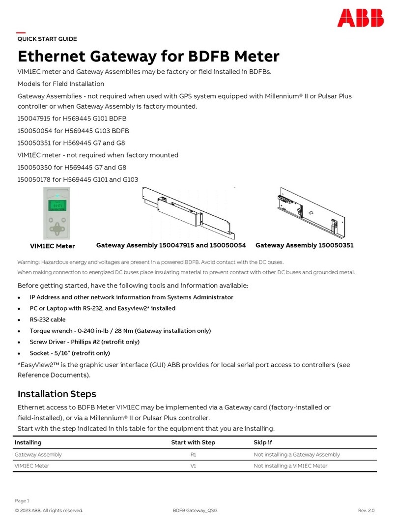
Other ABB Gateway manuals

ABB
ABB Cassia DODGE User manual

ABB
ABB VIM1EC User manual

ABB
ABB 83342-500 User manual

ABB
ABB Ability ATT-VZN SIM card ready gateway User manual

ABB
ABB 83330-5 Series User manual

ABB
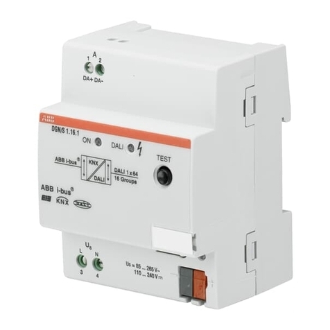
ABB DG/S 1.1 User manual

ABB
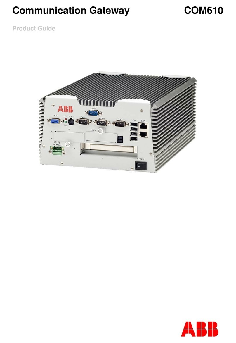
ABB COM 610 *2.1 User manual

ABB
ABB ARG600 ANSI User manual

ABB
ABB free@home SUG-F-1.1 User manual

ABB
ABB i-bus KNX User manual
Popular Gateway manuals by other brands

WiSilica
WiSilica lumos CONTROLS ENOR E Basic Installation and Quick Startup Guide

Huawei
Huawei B890 user guide

iiNet
iiNet TG-789 Quick setup guide

AudioCodes
AudioCodes Mediant 600 user manual

WELLTECH
WELLTECH WILLGATE2626 - RELEASE NOTE V106A release note

ZyXEL Communications
ZyXEL Communications VMG3925-B10A quick start guide