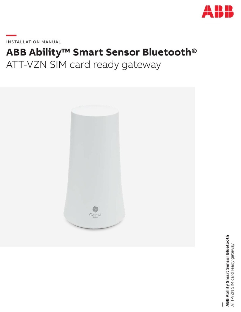
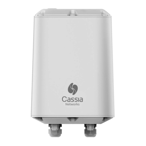
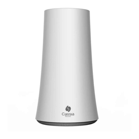
ABB Cassia DODGE User manual

DODGE® On-Premise Gateway User Guide
EtherNet/IP & OPC-UA

TABLE OF CONTENTS
1 INTRODUCTION............................................................................................................................... 1
1.1 System Requirements...............................................................................................................................................1
1.2 Tested OPC-UA Client Software ..............................................................................................................................1
1.3 Supported PLC Controllers ......................................................................................................................................1
1.4 References................................................................................................................................................................1
1.5 Acronyms ..................................................................................................................................................................1
2 PRELIMINARY STEPS ..................................................................................................................... 1
2.1 Login to Dashboard ..................................................................................................................................................1
2.2 Dashboard View .......................................................................................................................................................2
3 SENSOR MONITORING MANAGEMENT ....................................................................................... 2
3.1 Adding Sensors to Monitoring List ...........................................................................................................................3
3.2 Deleting Sensors from Monitoring List.....................................................................................................................3
3.3 Refreshing Monitoring List .......................................................................................................................................4
3.4 Changing Existing Options .......................................................................................................................................4
3.5 Viewing Sensor Details.............................................................................................................................................5
3.5.1 Measurement Tab ..........................................................................................................................................5
3.5.2 PLC List Tab (EtherNet/IP Page Only) ...........................................................................................................6
3.5.3 Settings Tab...................................................................................................................................................6
3.5.3.1 Measurement Interval and Accelerometer Range ...........................................................................6
3.5.3.2 Firmware Version..............................................................................................................................6
3.5.3.3 Synchronize Sensor Clock ...............................................................................................................6
3.5.3.4 Update Sensor Firmware .................................................................................................................7
3.6 Replacing a Sensor...................................................................................................................................................7
4 OPC-UA SERVER CONFIGURATION ............................................................................................. 8
4.1 Before You Begin ......................................................................................................................................................8
4.2 Connecting to OPC-UA Clients ................................................................................................................................8
4.2.1 Checking Sensor Parameters........................................................................................................................8
4.2.2 Monitor Sensor Parameter ............................................................................................................................9
4.2.3 Observing New Data of a Sensor Parameter ................................................................................................9
5 ETHERNET/IP CONFIGURATIONS................................................................................................. 9
5.1 Changing EtherNet/IP Operation..............................................................................................................................9
5.2 EtherNet/IP Tag Writer Operation.............................................................................................................................9
5.2.1 Viewing Sensor Details ..................................................................................................................................9
5.2.2 Conguring EtherNet/IP Tag Writer Inside Studio 5000..............................................................................10
5.3 CIP Server Operation.............................................................................................................................................. 11
5.3.1 Viewing Sensor Details ................................................................................................................................ 11
5.3.2 Conguring CIP Server inside Studio 5000 ................................................................................................ 11
5.3.3 Create New Module..................................................................................................................................... 13
5.3.4 Inputs and Outputs Data ............................................................................................................................. 14
5.3.5 Converting Data........................................................................................................................................... 15
6 UPDATING GATEWAY FIRMWARE/APPLICATION.......................................................................17
6.1 Update Gateway Firmware ..................................................................................................................................... 17
6.2 Update On-Premise Gateway Application ............................................................................................................. 18
7 KNOWLEDGE BASE .......................................................................................................................19
8 GLOSSARY......................................................................................................................................19
DODGE® On-Premise Gateway User Guide
1DODGE® On-Premise Gateway User Guide
1.3 Supported PLC Controllers
• Allen-Bradley - CompactLogix EtherNet/IP
- Tested PLCs
∙ 1769 L33ER Compact Logix 2 MB Memory
∙ 1769-L16ER-BB1B
1.4 References
• Open-source open62541.org licensed under the Mozilla
Public License at https://open62541.org/
• Open-source Rockwell Automation EtherNet/IP library
• DODGE® On-Premise Gateway Installation Manual at
https://search.abb.com/library/Download.aspx?Docum
entID=9AKK108402&LanguageCode=en&DocumentPar
tId=&Action=Launch
1.5 Acronyms
• EtherNet/IP – Ethernet Network for Industrial protocol
• OPC-UA – Open Platform Communications Unied
Architecture
• CIP – Common Industrial Protocol
• BLE – Bluetooth Low Energy
2 PRELIMINARY STEPS
2.1 Login to Dashboard
Connect your PC to the same network to which your gateway
is congured. Open your web browser (Google Chrome
recommended). Enter assigned Cassia IP Address and press
Enter. Enter Username and Password.
NOTE: For more information please refer to the DODGE® On-
Premise Gateway Installation Manual, section 2.3 and section
2.4, as linked in References section above.
1 INTRODUCTION
This guide describes how to use the Dodge On-Premise
Gateway that supports EtherNet/IP in an EtherNet/IP™
industrial protocol and OPC Unied Architecture (UA) to collect
data from ABB Smart Sensors for mechanical products.
The Key Performance Indicator (KPI) values are:
• Surface temperature
• Acceleration RMS
• Velocity RMS
The gateway application offers an interface for OPC-UA server
and EtherNet/IP that can support:
• Up to 20 ABB Smart Sensors for mechanical products
• Up to 10 OPC-UA clients
• Up to 5 EtherNet/IP based devices
This document provides step-by-step guidance through setup
congurations and mapping sensors to OPC-UA or EtherNet/IP
subsystems.
The typical functions of the gateway software are:
• Measurement interval and accelerometer range set up
• Sensor rmware update
• Sensor clock synchronization
• Back-up and restore conguration data
• Export historical data: last 24 hours and last 7 days
• Change unit values to metric or imperial
1.1 System Requirements
The Dodge On-Premise Gateway’s software requires the
following application components:
• Cassia X2000 gateway with rmware version: 2.1.0 or
latest
• Container version: 1.2.0 or latest
• Application version: 1.0 or latest
All the components are preinstalled on the gateway. In case
of manual installation or a software update, please refer to
section 6 of this guide.
1.2 Tested OPC-UA Client Software
• Prosys OPC
https://downloads.prosysopc.com/opc-ua-client-
downloads.php#download
• UaExpert from Unied Automation
https://www.unied-automation.com/downloads/opc-
ua-clients.html

2DODGE® On-Premise Gateway User Guide
3 SENSOR MONITORING MANAGEMENT
This gateway scans and captures BLE advertising packets
transmitted by ABB Smart Sensors for mechanical products.
The same sensor management is available on both the OPC-UA
and EtherNet/IP tabs, allowing users to execute the following
actions:
• Scan - show a list of active sensors within range of the
gateway
• Add - assign selected sensors that are in range of the
gateway
• Delete - remove selected sensors from the list
• Refresh - refresh the list of sensors in range of the
gateway in a regularly dened period or never
• Options - show more settings:
- Export/Conguration - export current list of
sensors and settings
- Export/Last 1 Day History
- Export/Last 7 Days History
- Export/Debug Logs
- Change Units: Imperial or Metric
• Details - show more information:
- Read sensor details and last performed
measurement
- Read/Update measurement interval and
accelerometer range
- Read rmware version
- Synchronize clock
- Update rmware
2.2 Dashboard View
Upon logging into the gateway, the Status tab is displayed by
default. Use the options along the top banner to select one of
the following:
• Select the OPC-UA tab to setup OPC-UA server
• Select the EtherNet/IP tab to setup EtherNet/IP
interface
Figure 1 - Cassia Login Page
Figure 2 - Dashboard View
Figure 3 - OPC-UA Page

3DODGE® On-Premise Gateway User Guide
After adding the sensors, the gateway will start to synchronize
the sensors' clocks. Wait for the synchronization process to
complete on all sensors and press OK.
3.2 Deleting Sensors from Monitoring List
To delete sensors from the monitoring list:
1. Select Sensors in the monitoring list.
2. Click Delete.
3. Click Yes.
3.1 Adding Sensors to Monitoring List
From the OPC-UA page (or EtherNet/IP page):
1. Click Scan.
2. Click Add on the chosen sensor.
NOTE: To add a sensor on the EtherNet/IP page, input the IP
address to the PLC controller.
Figure 4 - EtherNet/IP Page
Figure 5 - Add Sensor to OPC-UA
Figure 6 - Add Sensor to EtherNet/IP
Figure 7 - Sensor Synchronization
Figure 8 - Delete Sensors
Figure 9 - Delete Sensors Confirmation

4DODGE® On-Premise Gateway User Guide
To export les:
1. Click Export.
2. Click Configuration, 1 Day History, 7 Day History, or
Debug Logs.
To restore conguration:
1. Click Select File.
2. Locate the exported conguration le from Figure 13
(on your PC) and click Open.
3.3 Refreshing Monitoring List
To change refresh rate in the monitoring list:
1. Click on the Refresh drop-down list.
2. Choose desired option from list.
3.4 Changing Existing Options
To change existing options:
1. Click Options.
To change unit:
1. Select Imperial or Metric from the drop-down list.
2. Click Save.
Figure 10 - Refresh Rate
Figure 11 - Options Selection
Figure 12 - Unit Selection
Figure 13 - Export Files
Figure 14 - Select File
Figure 15 - Open File

5DODGE® On-Premise Gateway User Guide
The Measurement tab inside the EtherNet/IP page contains
the same information as the OPC-UA page, in addition to a
column based on the selected EtherNet/IP operation.
For selected CIP Server operation, there is an Input Array
parameter.
For selected EtherNet/IP tag writer operation, there is a PLC
Tag parameter.
For more information about how to change EtherNet/IP
operation, please refer to section 5.1.
NOTE: To learn more about what each sensor parameter
means, please refer to section 10 of the User Guide for Smart
Sensor Platform app and web portal for mechanical products
mentioned in section 1.4 of this guide.
3. Click Restore.
3.5 Viewing Sensor Details
Once all sensors have been added, the sensor data can be
viewed from within the OPC-UA or EtherNet/IP page:
• Click Details for the desired sensor.
The sensor details screen from the OPC-UA page contains 2
tabs, while the EtherNet/IP page contains 3 tabs.
3.5.1 Measurement Tab
The Measurement tab inside the OPC-UA page contains
information specic to the sensor such as the MAC address,
the serial number, and the sensor parameters data from the last
measurement performed.
Figure 16 - Restore Configuration Confirmation
Figure 17 - Sensor Details Selection
Figure 18 - Measurement Tab
Figure 19 - Input Array Parameter
Figure 20 - PLC Tag Parameter

6DODGE® On-Premise Gateway User Guide
3.5.3.2 Firmware Version
In order to read the rmware version on the sensor:
1. Click Read.
3.5.3.3 Synchronize Sensor Clock
In order to synchronize a sensor's clock:
1. Click Sync Sensor's Clock.
3.5.2 PLC List Tab (EtherNet/IP Page Only)
The PLC List tab appears only on the EtherNet/IP page and
contains the congured IP address of the PLC Controller which
is set when adding a sensor.
3.5.3 Settings Tab
3.5.3.1 Measurement Interval and Accelerometer Range
The Settings tab displays the sensor's current measurement
interval and accelerometer range and allows changes to be
made as needed.
By default, the sensor measurement interval is 1 hour and
the accelerometer range is 2g. However, if the measurement
interval and accelerometer range need to be changed, complete
the following steps:
1. Click on the Settings tab.
2. Click Read.
3. Select desired measurement interval (from 15 minutes
to 12 hours).
4. Select desired accelerometer range (up to 16g).
5. Click Write.
Figure 21 - PLC List Tab
Figure 22 - Settings Tab
Figure 23 - Settings Tab
Figure 24 - Firmware Version
Figure 25 - Synchronize Sensor's Clock

7DODGE® On-Premise Gateway User Guide
4. Wait for the new rmware installation to complete.
3.6 Replacing a Sensor
In case of a faulty sensor or a depleted sensor battery, replace
the old sensor with a new sensor using the steps below:
1. Delete the defective sensor from the monitoring list
inside the OPC-UA and EtherNet/IP pages.
3.5.3.4 Update Sensor Firmware
In order to update sensor rmware:
1. Click Select File.
NOTE: Please contact Smart Sensor for Mechanical
Products technical support by phone at +1 864-284-
5700 ext. 6 or by email at us-mptsensortechsupport@
abb.com to obtain the sensor rmware le.
2. Locate the sensor rmware le (on your PC) and click
Open.
3. Click Install.
Figure 26 - Select File
Figure 27 - Select Sensor Firmware
Figure 28 - Install Sensor Firmware
Figure 29 - Install Sensor Firmware
Figure 30 - Delete Sensor

8DODGE® On-Premise Gateway User Guide
4.2.1 Checking Sensor Parameters
1. Click on the triangle sign to expand Objects folder.
2. Click on the triangle sign next to the Sensor MAC
Address.
3. Click on the name of the variable (e.g. rms).
2. Add the new sensor to the OPC-UA and EtherNet/
IP pages using the steps listed in section 3.1 Adding
Sensors to Monitoring List.
NOTE: Be sure to change appropriate PLC tags from the
removed sensor to the new sensor in the Studio 5000 if you are
using EtherNet/IP tag writer operation. For more information
about PLC tags, please refer to section 5.2.2 Configuring
EtherNet/IP Tag Writer Inside Studio 5000.
4 OPC-UA SERVER CONFIGURATION
4.1 Before You Begin
Ensure that the OPC-UA clients can ping the gateway.
4.2 Connecting to OPC-UA Clients
There are many OPC-UA client software options available in the
industry. For this user guide, Prosys OPC UA Client is used.
1. Launch Prosys OPC UA Client application.
2. Write: opc.tcp://(IP address assigned to gateway by
the local area network):61210
(e.g. opc.tcp://192.168.0.192:61210)
3. Press Enter key to connect to server.
4. Select None below Security Mode and Security Policy.
5. Click OK.
Figure 31 - Connecting to the Server
Figure 32 - Security Settings
Figure 33 - Objects Folder
Figure 34 - Sensor MAC Address
Figure 35 - Variables

9DODGE® On-Premise Gateway User Guide
2. Select EtherNet/IP tag writer and click Save.
3. Or select CIP server and click Save.
5.2 EtherNet/IP Tag Writer Operation
Ensure EtherNet/IP tag writer operation is selected. Refer to
section 5.1 Changing EtherNet/IP Operation.
5.2.1 Viewing Sensor Details
To view selected sensor details:
1. Click Details for selected sensor.
4.2.2 Monitor Sensor Parameter
1. Right-click on the chosen variable.
2. Click Monitor.
4.2.3 Observing New Data of a Sensor Parameter
To observe new data of a certain variable:
1. Set Publishing Interval to 50.
2. Click on the checkbox in the Graph column.
3. Set Show Data for (seconds) to 3600.
4. Observe new data in the rms tab.
5 ETHERNET/IP CONFIGURATIONS
5.1 Changing EtherNet/IP Operation
EtherNet/IP setup supports two modes of operation. Select the
appropriate mode for the PLC prior to viewing sensor data.
From the Gateway EtherNet/IP page:
1. Select Options.
Figure 36 - Monitor Sensor Parameter
Figure 37 - Observing New Data
Figure 38 - EtherNet/IP Options
Figure 39 - Selecting EtherNet/IP Tag Writer
Figure 40 - Selecting CIP Server
Figure 41 - Viewing Sensor Details

10 DODGE® On-Premise Gateway User Guide
5.2.2 Configuring EtherNet/IP Tag Writer Inside Studio
5000
1. Launch Studio 5000 and open existing project.
2. Navigate to Controller Tags and then to Edit Tags.
3. Copy PLC Tags of specic sensor and create them.
Name Data Type
_xxxxxxxx_acc_rms DINT
_xxxxxxxx_vel_rms DINT
_xxxxxxxx_skin_temp DINT
_xxxxxxxx_time DINT
_xxxxxxxx_units DINT
NOTE: xxxxxxxx is the serial number of the selected sensor
(e.g. _10015901_acc_rms).
4. See example below with 2 sensors:
The Measurements tab contains information specic to the
sensor such as the MAC address, the serial number, and the
sensor parameters data from the last measurement performed.
See table below with PLC Tags and their types.
Parameter PLC Tag Type
Acceleration RMS _10015901_acc_rms DINT
Velocity RMS _10015901_vel_rms DINT
Surface Temperature _10015901_skin_temp DINT
Timestamp _10015901_time DINT
Units _10015901_units DINT
NOTE: [SN] = Serial Number of specic sensor (example:
_10021078_acc_rms).
PLC List tab contains information about congured IP
Addresses for PLC Controller.
To add a new PLC Controller to a specic sensor:
1. Write IP Address of PLC Controller.
2. Click Add.
Figure 42 - Sensor Details, Measurement Tab
Figure 43 - PLC List Tab
Figure 44 - Adding New PLC Controller to Sensor
Figure 45 - Open Existing Project
Figure 46 - Edit Tags
Figure 47 - Example

11 DODGE® On-Premise Gateway User Guide
See table below with Input Array and their types.
Parameter Input Array Type
Serial Number I.Data[0] DINT
Acceleration RMS I.Data[1] DINT
Velocity RMS I.Data[2] DINT
Surface Temperature I.Data[3] DINT
Timestamp I.Data[4] DINT
Units I.Data[5] DINT
NOTE: Number inside brackets represents an index number in
Input Array in CIP Server.
5.3.2 Configuring CIP Server inside Studio 5000
1. Launch Studio 5000 and create new project.
2. Click on Logix tab.
3. Select a PLC type and type a name for the project in
the Name eld.
4. Click Next.
5. Click Finish. New instance of Logix designer will be
opened.
5. Save the project. Upload tags when prompted.
6. Navigate to monitor tags.
5.3 CIP Server Operation
5.3.1 Viewing Sensor Details
Ensure CIP operation is selected. Refer to section 5.1
Changing EtherNet/IP Operation.
To view selected sensor details:
1. Click Details for selected sensor.
The Measurement tab contains information specic to the
sensor such as the MAC address, the serial number, the list
of Input Array and the sensor parameters data from the last
measurement performed.
Figure 48 - Upload Tags Prompt
Figure 49 - Monitor Tags
Figure 50 - Viewing Sensor Details
Figure 51 - Measurement Tab
Figure 52 - Create New Project
Figure 53 - Select PLC Type & Name New Project

12 DODGE® On-Premise Gateway User Guide
8. Click Download.
9. After it has downloaded, controller mode can be
changed back to remote run. Click Yes.
6. Choose Select Path button.
7. Select your controller.
Figure 54 - Finish New Project
Figure 55 - Select Path
Figure 56 - Select Controller
Figure 57 - Download Controller
Figure 58 - Download Process
Figure 59 - Remote Run Confirmation

13 DODGE® On-Premise Gateway User Guide
3. Find Generic Ethernet Module on the list.
4. Select Generic Ethernet Module and click Create.
5. Input the following data.
Parameter Name Value
Name Cassia
IP Address 192.162.0.40 [1]
Comm Data - DINT
Input (Assembly Instance) 100
Input (Size) 120 [2]
Output (Assembly Instance) 150
Output (Size) 1
Conguration (Assembly Instance) 151
Conguration (Size) 4
[1] - Assigned Cassia IP during local network conguration
[2] - Reserved locations for 6 parameters*20 sensors.
6. Click OK.
7. Change Requested Packet Interval to 200ms and
click OK.
10. When everything is ready, Logix designer shows Rem
Run in the marked box:
5.3.3 Create New Module
1. Click Go Offline.
2. Right-click on Ethernet and choose New Module.
Figure 60 - Remote Run
Figure 61 - Go Offline
Figure 62 - New Module
Figure 63 - Create New Ethernet Module
Figure 64 - New Module Dialogue Box

14 DODGE® On-Premise Gateway User Guide
3. Click Go Online.
4. Download the project into the controller.
5. Each Tag Value corresponds to each parameter
position shown in section 3.5 Viewing Sensor Details,
Measurement Tab of the EtherNet/IP Page.
5.3.4 Inputs and Outputs Data
1. Double-click on the Controller Tags in the Controller
Organizer.
2. Expand Cassia:I.Data.
Figure 65 - Requested Packet Interval
Figure 66 - Controller Organizer
Figure 67 - Controller Tags
Figure 68 - Go Online
Figure 69 - Download Project
Figure 70 - Measurement Tab

15 DODGE® On-Premise Gateway User Guide
3. Go back to Controller Tags, and Go Offline to create
the following tags:
Name Data Type
vel_rms_divider DINT
acc_rms_divider DINT
skin_temp_divider DINT
sensor1_serial_number DINT
sensor1_acc_rms REAL
sensor1_vel_rms REAL
sensor1_skin_temp REAL
sensor1_units BOOL
sensor1_time DINT
4. Go Offline to change Data Type.
5. Double-click MainProgram.
6. Go to the Configuration tab and select Conversion for
Main and <none> For Fault.
5.3.5 Converting Data
1. Right-click on Tasks / MainProgram and choose Add
New Routine.
2. Write Name: Conversion and select Type: Structured
Text. Click OK.
Figure 71 - Tag Value
Figure 72 - Add New Routine
Figure 73 - New Routine Dialogue Box
Figure 74 - Go Offline
Figure 75 - Controller Tags

16 DODGE® On-Premise Gateway User Guide
11. Go to Monitor Tags tab and observe the converted
values.
• Vel_rms is in in [/s] or[ mm/s]
• Acc_rms is in [g] rms unit
• Skin_temp is in [°F] or [°C]
• If units is 0 the system is [metric], if 1 the system is
[imperial].
• Time is the Unix timestamp – number of seconds since
January 1, 1970.
7. Click OK.
8. Go to Conversion and paste the following text into the
Conversion routine:
vel_rms_divider := 1000;
acc_rms_divider := 2048;
skin_temp_divider := 10;
sensor1_serial_number := cassia:I.Data[0];
sensor1_acc_rms := cassia:I.Data[1]/acc_rms_divider;
sensor1_vel_rms := cassia:I.Data[2]/vel_rms_divider;
sensor1_skin_temp := cassia:I.Data[3]/skin_temp_
divider;
sensor1_time := Cassia:I.Data[4];
sensor1_units := cassia:I.Data[5].0;
9. Click Save.
10. Go Online and download program to PLC.
Figure 76 - MainProgram
Figure 77 - Conversion
Figure 78 - Save
Figure 79 - Go Online
Figure 80 - Download Program
Figure 81 - Converted Values

17 DODGE® On-Premise Gateway User Guide
Click Upgrade to start updating the router's rmware and wait
until the process has completed.
6 UPDATING GATEWAY FIRMWARE/
APPLICATION
6.1 Update Gateway Firmware
Login to the gateway by following the instructions from section
2.1. From the top banner, click Other tab.
Scroll down to Update Router's Firmware and click on Select
File.
NOTE: Please contact Smart Sensor for Mechanical Products
technical support by phone at +1 864-284-5700 ext. 6 or by
email at us-mptsensortechsupport@abb.com to obtain the
rmware le.
Locate the le (on your PC) provided to update the router's
rmware and click Open.
Figure 82 - Click on Other Tab
Figure 83 - Update Router's Firmware
Figure 84 - Open Router's Firmware File
Figure 85 - Upgrade Router's Firmware

18 DODGE® On-Premise Gateway User Guide
Click Install to start installing the application and wait until the
process is complete.
Once the installation is complete, the application with a version
number should display as shown below.
6.2 Update On-Premise Gateway
Application
Login to the gateway by following the instructions from section
2.1. From the top banner, click on Container tab.
Scroll down to the Installed APP(s) section and click on Select
File.
NOTE: To download the On-Premise Gateway application le,
follow the link below. The application le will be under Software
in the Literature tab.
https://dodge.ptplace.com/productDetail/_pn=749923?referenc
e=TopNav&searchTerm=749923
Locate the le (on your PC) provided to install application and
click Open.
Figure 87 - Container Tab
Figure 88 - Install APP
Figure 89 - Open Application File
Figure 90 - Install Application
Figure 91 - Updated Application
Table of contents
Other ABB Gateway manuals

ABB
ABB M2302 User manual

ABB
ABB DG/S 1.1 User manual

ABB
ABB MicroSCADA Pro SYS 600C User manual

ABB
ABB Ability User manual

ABB
ABB SPA-ZC 302 Guide

ABB
ABB ARG600 ANSI User manual

ABB
ABB Pluto Series Use and care manual

ABB
ABB TG/S 3.1 User manual

ABB
ABB i-bus KNX MG/S 11.100.1.1 User manual

ABB
ABB M2302 User manual