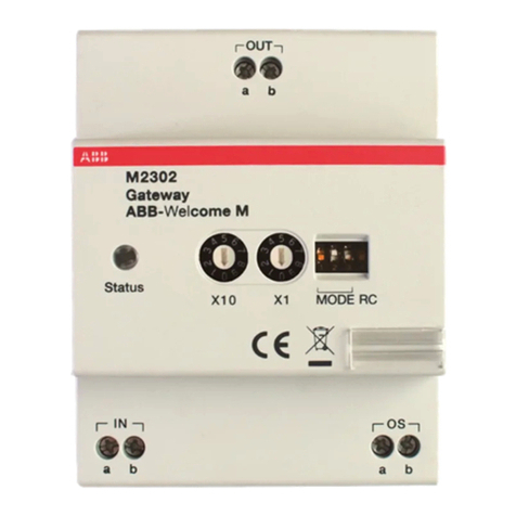
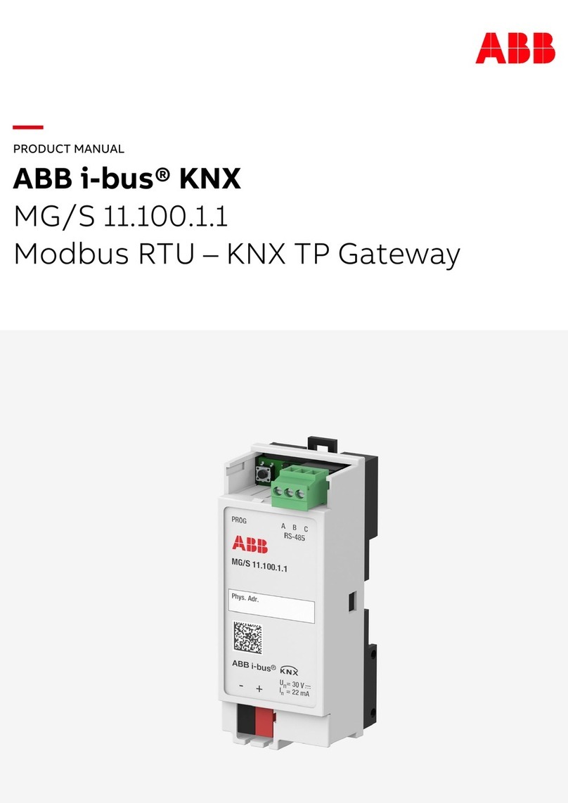
ABB M2302 User manual

VER:1.1 │ │ 25.09.2015
ABB-Welcome
Pos: 2/Di nA4 - Anleitung enO nline/Inhalt/KNX/D oorEntry/832 20-AP-xxx/Tit elblatt - 83220-AP-xxx - ABB @ 19\mod_1 323249806476_15. docx@ 11 1084@ @ 1
M2302
Gateway
=== Ende der List ef ür Textmar keCo ver ===

ABB-Welcome
|
—2 —
Pos: 4 /Busch-Ja eger( Neustruktur)/M odul-Stru ktur/Online-Dokumen tation/Inhalts verzeichnis (--> Für alleD okumente <--)/I nhaltsverzeichnis @ 19\ mod_1320649044386_1 5.docx@ 1 09653 @ @ 1
1Safety............................................................................................................3
2Intended use..................................................................................................3
3Environment ..................................................................................................3
3.1 ABB devices.................................................................................3
4Operation.......................................................................................................5
4.1 Control elements ..........................................................................5
4.2 Operating modes..........................................................................6
4.2.1 Building gateway ..........................................................................6
4.2.2 Floor gateway...............................................................................8
4.2.3 Apartment gateway.....................................................................12
4.2.4 Additional power supply mode....................................................15
4.2.5 Line amplifier ..............................................................................18
5Technical data.............................................................................................20
6Mounting/Installation....................................................................................21
6.1 Requirements for the electrician.................................................21
6.2 General installation instructions..................................................22
6.3 Mounting.....................................................................................22
=== Ende der Liste fürT extmarke TOC ===

ABB-Welcome
Safety
|
—3 —
Pos: 6 /Busch-Ja eger( Neustruktur)/M odul-Stru ktur/Online-Dokum entation/Überschrift en( --> Füralle Do kumente <--)/1. Ebene/S - T/Sicherheit @ 1 8\mod_1302612791 790_15.docx @ 103357 @ 1 @ 1
1 Safety
Pos: 7/ Busch-Jaeger (Neus truktur)/Modul-Str uktur/Online-Dokum entation/Sicherheit (--> Für alle Doku mente< --)/Warnhin weise/Sicherheit - 230 V @ 18\mod_1302606 816750_15.docx @ 103308 @ @ 1
Warning
Electric voltage!
Risk of death and fire due to electrical voltage of 100-240 V.
–Work on the 100-240V supply system may only be performed by
authorized electricians!
–Disconnect the main power supply prior to installation and/or
disassembly!
Pos: 8 /Busch-Ja eger( Neustruktur)/M odul-Stru ktur/Online-Dokum entation/Überschrift en( --> Füralle Do kumente <--)/1. Ebene/A - F/Besti mmungsgemäßer Gebrauch @ 18\mod_ 1302763321316_1 5.docx@ 1 03483 @ 1 @ 1
2 Intended use
Pos: 9/Di nA4 - Anleitung enO nline/Inhalt/KNX/D oorEntry/832 20-AP-xxx/B estimmungsg emaesser Gebra uch- 8 3220-AP-xxx-500 @ 20\mod_1 324561168699_15.d ocx@ 1 12728 @ @ 1
This device is an integral part of the ABB-Welcome door communication system and
operates exclusively with components from this system. The device must only be
installed on mounting rails according to DIN EN 500022.
Pos: 10 /Busch-Jaeg er( Neustruktur)/Mo dul-Struktur/Onlin e-Dokumentation/Üb erschriften (--> Für alleD okument e<--) /1. Ebene/U -Z/U mwelt @ 18\mod_1302 614158967_15.docx @ 10 3383@ 1 @ 1
3 Environment
Pos: 11 /Busc h-Jaeg er (Neustr uktur)/Modul- Struktur/O nline-Doku mentation/U mwelt (--> Für alleD okum ente<--)/Hi nweise/Hin weis- U mwelt- Hinweis Ele ktrogeräte@ 18\m od_130276397343 4_15.docx @ 103500 @ @1
Consider the protection of the environment!
Used electric and electronic devices must not be disposed of with
domestic waste.
–The device contains valuable raw materials that can be recycled.
Therefore, dispose of the device at the appropriate recycling
facility.
Pos: 12 /DinA4 - Anleitunge n Online/Ueberschrif ten/2./ABB Gera ete@ 1 9\mod_132 3162843832_15.doc x@ 1 10875 @ 2 @ 1
3.1 ABB devices
Pos: 13 /Busc h-Jaeg er (Neustr uktur)/Modul- Struktur/O nline-Doku mentation/U mwelt (--> Für alleD okum ente<--)/Hi nweise/Hin weis- U mwelt- ABB Ele ktrogeräte@ 19\m od_1323162745839_1 5.docx @ 110867 @ @1
All packaging materials and devices from ABB bear the markings and test seals for
proper disposal. Always dispose of the packaging material and electric devices and their
components via an authorized recycling facilities or disposal companies.

ABB-Welcome
Environment
|
—4 —
ABB products meet the legal requirements, in particular the laws governing electronic
and electrical devices and the REACH ordinance.
(EU-Directive 2002/96/EG WEEE and 2002/95/EG RoHS)
(EU-REACH ordinance and law for the implementation of the ordinance (EG)
No.1907/2006)

ABB-Welcome
Operation
|
—5 —
Pos: 18 /DinA4 - Anleitungen Online/Ue berschriften/1./Bedi enung @ 18\mod_1302613 924165_15.docx @ 103365 @ 1 @ 1
4 Operation
Pos: 19 /DinA4 - Anleitunge n Online/Ueberschrif ten/2./Norm aler Betrieb @ 18\mod_ 1302768820965_ 15.docx @ 103540 @ 2 @ 1
4.1 Control elements
Pos: 20 /DinA4 - Anleitunge n Online/Ueberschrif ten/3./Bedienel emente @ 20\mod_ 132326022055 9_15.docx @ 111647 @ 3 @ 1
Pos: 21 /DinA4 - Anleitunge n Online/Inhalt/KN X/DoorEntry/83 220-AP-xxx/Bedieneleme nte- 83220-AP- xxx @ 18\mod_13032 12853605_15.doc x@ 103673 @ @ 1
Fig.
1
: Overview of control buttons
No.
Functions
1
Bus in/out
2
Operating mode settings: See chapter “Operating modes”for details.
3
Terminal resistor ON/OFF.
In video installations or audio- and video-combined installations, the switch
must be set as “RC on”on the last device of the line.
4
Rotary switches for addressing (01-99).
5
Connection with outdoor stations, or connection with bus in, in "line
amplifier" mode.
6
Operating status indicating LED
Pos: 22 /Busch-J aeger (Neustru ktur)/Modul-Struktur /Online-Doku mentation/Steu ermodule - Onli ne-Dokumentation (--> F üralle Do kumente <--)/+++++ +++++++ Seitenumbruch +++++++ +++++ @ 9\mod_1268 898668093_0.doc x@ 52149 @ @ 1

ABB-Welcome
Operation
|
—6 —
Pos: 26 /DinA4 - Anleitunge n Online/Ueberschrif ten/2./Bediena ktionen @ 20\mod_1 323262294281_1 5.docx @ 111911 @ 2 @ 1
4.2 Operating modes
Pos: 71 /DinA4 - Anleitunge n Online/Ueberschrif ten/3./Abschlus swiderstand @ 19\m od_132195807 9906_15.docx @ 1100 83@ 3 @ 1
Pos: 72 /DinA4 - Anleitunge n Online/Inhalt/KN X/DoorEntry/Be dienung/Abschl usswiderstand setzen 8 3220-AP-xxx @ 19\m od_1310723392369 _15.docx @ 107841 @ @1
4.2.1 Building gateway
Fig.
2
: Building gateway
No.
Functions
1
1->OFF, 2->OFF, 3->OFF
Pos: 74 /DinA4 - Anleitunge n Online/Inhalt/KN X/DoorEntry/Be dienung/Master/Sl aveS chalter setzen 83 220-AP-xxx @ 19\mod_1310723 320966_15.docx @ 107833 @ @
2
3
ON
1
1

ABB-Welcome
Operation
|
—7 —
Enable one building as an independent sub-system (outdoor station(s)/guard unit(s) can
be connected). Up to 60 such systems are supported within the whole system.
The gateway address is equal to the riser number.
Fig.
3
: Building gateway
Wiring diagram:
Fig.
4
: Building gateway

ABB-Welcome
Operation
|
—8 —
4.2.2 Floor gateway
Fig.
5
: Floor gateway
No.
Functions
1
1->OFF, 2->OFF, 3->ON
2
3
ON
1
1

ABB-Welcome
Operation
|
—9 —
Enable a multi-apartment as an independent sub-system (another outdoor station can
be connected, for example in front of the door of the floor with the multi-apartment).
The gateway address is equal to the minimum address of the indoor station inside the
sub-system.
Fig.
6
: Floor gateway

ABB-Welcome
Operation
|
—10 —
Wiring diagram:
Fig.
7
: Floor gateway
If using pushbutton outdoor station as a gate station, floor gateway is available for this
kind of use case.
In following example, an outdoor station is mounted at the gate entrance with which all
six apartments can be called. One outdoor station is on the left building with apartments
01 and 03 and a further outdoor station on the right building with apartments 04 and 05.
This means that only three apartments can be called from these two outdoor stations.
Using floor gateway for each building, and outdoor station 1 can manage these two
buildings, while outdoor station 2 manage the left building and outdoor station 3 manage
the right one.

ABB-Welcome
Operation
|
—11 —
Wiring diagram (using floor gateway for each building)
Apartment 01 A
Apartment 02 B
Apartment 03 C
Apartment 04 A
Apartment 05 B
Apartment 06 C
Outdoor station
Left building
Apartment 01 A
Apartment 02 B
Apartment 03 C
Apartment 04 D
Apartment 05 E
Apartment 06 F
Outdoor station
Gate entrance
Outdoor station
Right building
Apartment 01 A
Apartment 02 B
Apartment 03 C
Apartment 04 A
Apartment 05 B
Apartment 06 C
Apartment 01 A
Apartment 02 B
Apartment 03 C
Apartment 04 D
Apartment 05 E
Apartment 06 F
ST. X100 X10 X1
2 0 0 3
ST. X100 X10 X1
2 0 0 2
ST. X100 X10 X1
2 0 0 1
Address
2
Address
1
Address
3
ST. X100 X10 X1
3 0 0 4
ST. X100 X10 X1
3 0 0 5
ST. X100 X10 X1
3 0 0 6
M2302
X10 X1
0 1
M2302
X10 X1
0 4

ABB-Welcome
Operation
|
—12 —
4.2.3 Apartment gateway
Fig.
8
: Apartment gateway
No.
Functions
1
1->OFF, 2->ON, 3->OFF
2
3
ON
1
1

ABB-Welcome
Operation
|
—13 —
Enable one apartment as an independent sub-system (The 2nd confirmed outdoor
station can be connected). Up to 99 such systems can be supported within the whole
system.
The gateway address is equal to the apartment number.
Fig.
9
: Apartment gateway

ABB-Welcome
Operation
|
—14 —
Wiring diagram:
Fig.
10
: Apartment gateway

ABB-Welcome
Operation
|
—15 —
4.2.4 Additional power supply mode
Fig.
11
: Additional power supply mode
No.
Functions
1
1->OFF, 2->ON, 3->ON
2
3
ON
1
1

ABB-Welcome
Operation
|
—16 —
Enable an additional power source for systems with a system controller.
Fig.
12
: Additional power supply mode
Using gateway
+ system
controller as
auxiliary power
supply to
connect to
other indoor
stations in the
same building,
when one
system
controller can’t
cover all
consmer units.
★
★
★

ABB-Welcome
Operation
|
—17 —
Wiring diagram:
Fig.
13
: Additional power supply mode

ABB-Welcome
Operation
|
—18 —
4.2.5 Line amplifier
Fig.
14
: Line amplifier
No.
Functions
1
1->ON, 2->OFF, 3->OFF
Strengthen the video signal and extend transmission. For increased distance please
refer to ABB-Welcome system manual.
Fig.
15
: Line amplifier
2
3
ON
1
1

ABB-Welcome
Operation
|
—19 —
Wiring diagram:
Fig.
16
: Line amplifier
Pos: 75 /Busch-J aeger (Neustru ktur)/Modul-Struktur /Online-Doku mentation/Steu ermodule - Onli ne-Dokumentation (--> F üralle Do kumente <--)/+++++ +++++++ Seitenumbruch +++++++ +++++ @ 9\mod_1268 898668093_0.doc x@ 52149 @ @ 1

ABB-Welcome
Technical data
|
—20 —
Pos: 76 /DinA4 - Anleitunge n Online/Ueberschrif ten/1./Technisc heD aten @ 18\mo d_1302615863001_ 15.docx @ 103416 @ 1 @ 1
5 Technical data
Pos: 77 /DinA4 - Anleitunge n Online/Inhalt/KN X/DoorEntry/83 220-AP-xxx/Technische Daten - 83220-AP-xxx @ 18\mod_13032 12854559_15.doc x@ 103 705@ @ 1
Designation
Value
Operating temperature
-25 °C - +55 °C
Protection
IP20
Single-wire clamps
2 x 0.28 mm²- 2 x 0.75 mm²
Fine-wire clamps
2 x 0.28 mm²- 2 x 0.75 mm²
Bus voltage
20-30 V
Pos: 78 /Busch-J aeger (Neustru ktur)/Modul-Struktur /Online-Doku mentation/Steu ermodule - Online-D okumentation (--> F üralle Do kumente <--)/++++++ ++++++ Seitenumbruch ++++++++ ++++ @ 9\mod_12688 98668093_0.docx @ 52149 @ @1
Other manuals for M2302
2
Table of contents
Other ABB Gateway manuals
Popular Gateway manuals by other brands

Dinstar
Dinstar DAG2000-16S Quick installation guide

Atop
Atop PG5901B Series Configuration manual

WEBLE
WEBLE S485 installation instructions

Yeastar Technology
Yeastar Technology NeoGate user manual

Technicolor
Technicolor MediaAccess TG389ac installation guide

AudioCodes
AudioCodes MediaPack 1288 Quick setup guide