4
1.3 Manovre normali
1.3.1 Sull'interruttore
a) Inserzione: primadieffettuarelamanovra,verificarechesia
disattivatoilblocco descritto alpunto1.2.1equanto descrit-
to nelle istruzioni del contenitore.
b) Sezionamento: per passare dalla posizione di inserito a
quella di sezionato verificare che l'interruttore sia aperto.
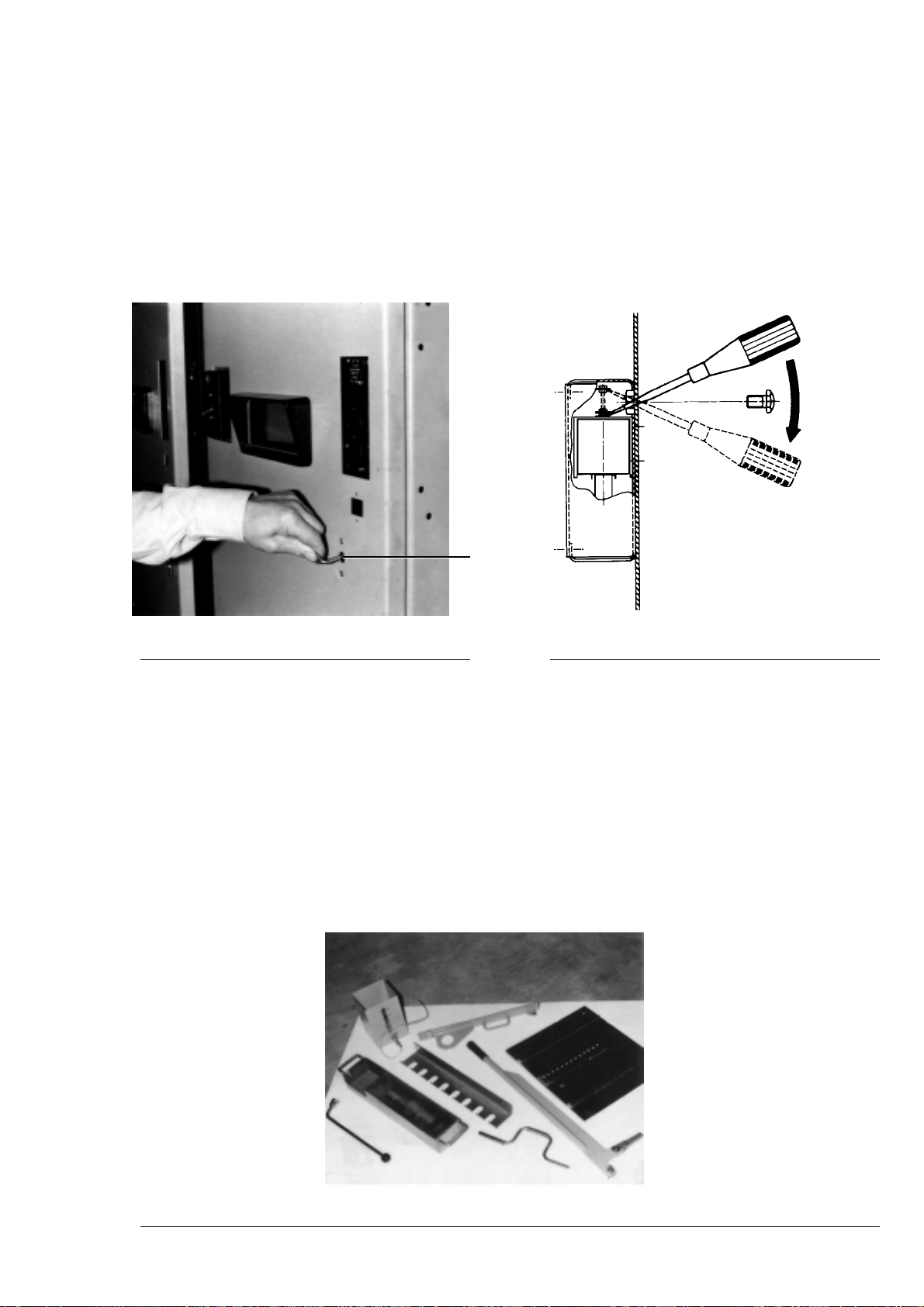
1.3.2 Sul sezionatore di terra
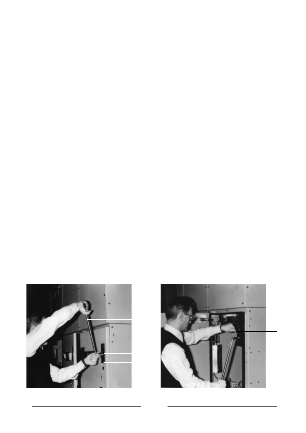
a) Azionamento:lalevadicomando(fig.3a)unavoltaintrodot-
ta nella propria sede (fig. 3b) e iniziata la sua rotazione,
rimane vincolata fino a quando non è stata completata la
manovra;dopodichevieneespulsaper effettodiunamolla.
Senonsi riesce aintrodurrelamanigliavuoldireche manca
il consenso dei blocchi citati al punto 1.2.2.
b) Blocco a chiave: introdurre la chiave nella serratura (fig. 3c)
eruotarlainsensoorario di circa 90°quindiintrodurrelaleva
di manovra (fig. 3a).
c) Chiusura sezionatore: verificare che siano disattivati i bloc-
chiprevistialpunto1.2.2;inserirelalevadimanovra(fig.3a)
e ruotare di 180° in senso antiorario.
d) Apertura sezionatore: verificare che siano disattivati i bloc-
chiprevistialpunto1.2.2;inserirelalevadimanovra(fig.3a)
e ruotare di 180° in senso orario.
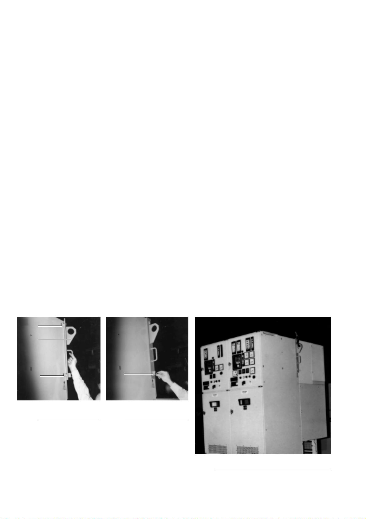
1.3.3 Sulla porta posteriore cella linea
a) Apertura: verificare che sia disattivato il blocco descritto al
punto 1.2.3 (sezionatore di terra chiuso) e ruotare la mani-
glia in senso antiorario.
1.4 Manovre di emergenza
Le manovre qui sotto descritte devono essere eseguite esclu-
sivamente in caso di assoluta necessità da personale qualifica-
to che ne assume tutta la responsabilità. ABB SACE declina la
propria responsabilità circa le conseguenze che possono deri-
vare da un eventuale errata manovra.
1.4.1 Sull'interruttore
a) Consultare le istruzioni del contenitore
1.4.2 Sull'apertura del sezionatore di terra
a) Qualorasivogliaeffettuarel'aperturaconlaportaposteriore
aperta premere a fondo il perno di blocco (fig. 4a) e
contemporaneamente inserire la leva di comando come
scritto al punto 1.3.2.
1.3 Normal operations
1.3.1 On the circuit-breaker
a) Connection: before carrying out the operation, check that
the lock described in point 1.2.1 is inactivated and that the
instructions for the enclosure are followed.
b) Isolation: to pass from the connected to isolated position,
check that the circuit-breaker is open.
1.3.2 On the earthing switch
a) Activation: once the operating lever (fig. 3a) has been
insertedinitsseat(fig.3b)anditsrotationstarted,itremains
locked until the operation has been completed. After this, it
is ejected by means of a spring.
If the lever cannot be inserted, it means that consent of the
lock mentioned in point 1.2.2 is missing.
b) Key lock: Insert the key in the lock (fig. 3c) and turn it about
90° clockwise, then insert the operating lever (fig. 3a).
c) Earthing switch closure: check that the locks mentioned in
point 1.2.2 are inactivated. Insert the operating lever (fig.
3a) and turn it 180° clockwise.
d)
Earthing switch opening: check that the interlocks of point
1.2.2 give the consent; insert the operating lever (fig. 3a)
and turn clockwise of 180°.
1.3.3 On the feeder compartment rear door
a) Opening: check that the lock described in point 1.2.3
(earthing switch closed) is inactivated, and turn the lever
anticlockwise.
1.4 Emergency operations
The operations described below must only be carried out in
case of absolute necessity and by qualified personnel who take
fullresponsibilityforthem.ABB SACEdeclinesallresponsibility
for any consequences due to incorrect operation.
1.4.1 On the circuit-breaker
a) Consult the instructions for the enclosure
1.4.2 On earthing switch opening
a) When opening must be carried out with the rear door open,
press the locking pin (fig. 4a) in fully and at the same time
insert the operating lever as described in point 1.3.2.
Fig. 3 Fig. 4
a
b
c
a