manuals.online logo
Brands
  1. Home
  2. •
  3. Brands
  4. •
  5. ABB
  6. •
  7. Industrial Equipment
  8. •
  9. ABB SmissLine Classic 2CCC404012M0104 User manual

ABB SmissLine Classic 2CCC404012M0104 User manual

This manual suits for next models

1

Other ABB Industrial Equipment manuals

ABB HT568787 User manual

ABB

ABB HT568787 User manual

ABB XAC24837 User manual

ABB

ABB XAC24837 User manual

ABB HT598325 User manual

ABB

ABB HT598325 User manual

ABB HT598351 User manual

ABB

ABB HT598351 User manual

ABB HT578604 User manual

ABB

ABB HT578604 User manual

ABB HT564657 User manual

ABB

ABB HT564657 User manual

ABB TPS48 Series User manual

ABB

ABB TPS48 Series User manual

ABB HT563830 User manual

ABB

ABB HT563830 User manual

ABB HT563058 User manual

ABB

ABB HT563058 User manual

ABB HT845109 User manual

ABB

ABB HT845109 User manual

ABB HT608934 User manual

ABB

ABB HT608934 User manual

ABB HT578832 User manual

ABB

ABB HT578832 User manual

ABB HT603327 User manual

ABB

ABB HT603327 User manual

ABB HT610306 User manual

ABB

ABB HT610306 User manual

ABB HT563322 User manual

ABB

ABB HT563322 User manual

ABB HT842415 User manual

ABB

ABB HT842415 User manual

ABB HT563221 User manual

ABB

ABB HT563221 User manual

ABB HT563366 User manual

ABB

ABB HT563366 User manual

ABB HT602578 User manual

ABB

ABB HT602578 User manual

ABB XAC25339 User manual

ABB

ABB XAC25339 User manual

ABB HT844038 User manual

ABB

ABB HT844038 User manual

ABB BEP140-30 User manual

ABB

ABB BEP140-30 User manual

ABB HT591186 User manual

ABB

ABB HT591186 User manual

ABB TPL85-B12 User manual

ABB

ABB TPL85-B12 User manual

Popular Industrial Equipment manuals by other brands

G.B.C BASIC EDGE 50 instruction manual

G.B.C

G.B.C BASIC EDGE 50 instruction manual

Tronair Batpak 11-6602-1000 Operation & service manual

Tronair

Tronair Batpak 11-6602-1000 Operation & service manual

Pilz PNOZ mi2p Operation manual

Pilz

Pilz PNOZ mi2p Operation manual

Clemco Zero BNP 6012 manual

Clemco

Clemco Zero BNP 6012 manual

Erskine Attachments V-Plow Operator's manual

Erskine Attachments

Erskine Attachments V-Plow Operator's manual

Morra MH 540 user manual

Morra

Morra MH 540 user manual

Eaton S090ST manual

Eaton

Eaton S090ST manual

GRIGGIO G 240 P4 instructions

GRIGGIO

GRIGGIO G 240 P4 instructions

Nexen AIR CHAMP HT45 user manual

Nexen

Nexen AIR CHAMP HT45 user manual

WTE V5 installation manual

WTE

WTE V5 installation manual

SMC Networks CJP Series Operation manual

SMC Networks

SMC Networks CJP Series Operation manual

JohnDow Industries JDI-AFT58 Operator's manual

JohnDow Industries

JohnDow Industries JDI-AFT58 Operator's manual

IMB MB9016A instruction manual

IMB

IMB MB9016A instruction manual

Clarke CUMB1 Assembly & operating instructions

Clarke

Clarke CUMB1 Assembly & operating instructions

amiad Arkal Spin Klin 2 user guide

amiad

amiad Arkal Spin Klin 2 user guide

Maxima GIUNTOMAX Use and maintenance manual

Maxima

Maxima GIUNTOMAX Use and maintenance manual

Grizzly T32428 owner's manual

Grizzly

Grizzly T32428 owner's manual

Siemens 8MF1 Series operating instructions

Siemens

Siemens 8MF1 Series operating instructions

manuals.online logo
manuals.online logoBrands
  • About & Mission
  • Contact us
  • Privacy Policy
  • Terms and Conditions

Copyright 2025 Manuals.Online. All Rights Reserved.

1
Positioning auxiliary or signal contacts on the
device:
Miniature circuit-breaker optionally left or right
4-pole residual-current circuit-breaker right
2-pole residual-current circuit-breaker right
Residual-current circuit-breaker/min-
iature circuit-breaker right
SMISSLINE CLASSIC bearing rail auxiliary and signal
contacts cannot be fitted to SMISSLINE plug-in systems.
Assembly right
Fig. 1 Position the connecting pin in accordance with the
contacting of the residual-current circuit-breaker
or miniature circuit-breaker.
Disconnection right
Fig. 2
Assembly / Disconnection left
Fig. 3 / Fig. 4
Garanzia I
Il funzionamento sicuro del dispositivo è garantito nel caso
in cui le operazioni di montaggio descritte nelle presenti
istruzioni per l’uso siano state eseguite correttamente e
che sia stato effettuato il controllo di funzionamento prima
e durante l’esercizio del dispositivo, come descritto nelle
presenti istruzioni per l’uso.
Sicurezza
Non dev’essere eseguita alcuna riparazione all’interruttore
magnetotermico.
Smaltimento
Gli apparecchi difettosi devono essere smaltiti come rifiuti
speciali presso i centri di raccolta corrispondenti. Ci si deve
attenere alle normative nazionali e regionali in materia di
smaltimento dei rifiuti speciali.
Descrizione del funzionamento
Contatti ausiliari: scattano contemporaneamente ai contatti
del dispositivo di protezione (azionamento manuale o
automatico).
Contatti di segnalazione: scattano con l’azionamento elettrico
del dispositivo di protezione, in seguito a cortocircuito o
corrente di guasto.
Per ciascun dispositivo di protezione possono essere
montati:
1 blocco di contatti ausiliari
oppure 1 blocco di contatti di segnalazione
oppure 2 blocchi di contatti ausiliari
oppure 1 blocco di contatti di segnalazione ed
1 blocco di contatti ausiliari.
Verifica funzionamento
Dopo il montaggio, è necessario verificare il corretto
funzionamento dei contatti ausiliari e di segnalazione.
Controllare inoltre con uno strumento di collaudo
appropriato che i contatti ausiliari e di segnalazione scattino
correttamente.
Nei blocchi dei contatti di segnalazione il tastino di color
arancio deve essere chiaramente sporgente.
Dopo aver premuto il pulsante di test di colore grigio il
contatto deve scattare. Dopo ogni azionamento il contatto
dev’essere riportato nella sua posizione iniziale con l’ausilio
del tasto di reset di color arancio.
Posizionamento dei contatti ausiliari o
di segnalazione nell’apparecchio
Interruttore magnetotermico a scelta a sinistra o a destra
Interruttore differenziale quadripolare a destra
Interruttore differenziale bipolare a destra
Interruttore differenziale e interruttore magnetotermico
a destra
I contatti ausiliari e di segnalazione degli apparecchi
per binari di supporto SMISSLINE CLASSIC non
possono essere montati sui sistemi di connes-
sione degli apparecchi SMISSLINE.
Montaggio olestra
Fig.1 Posizionare il perno di collegamento in funzione
dei contatti dell’interruttore differenziale o
dell’interruttore magnetotermico.
Smontaggio olestra
Fig. 2
Montaggio / Smontaggio sinistra
Fig. 3 / Fig. 4
1
2
2
1
2
1
Warning! Installation by person with electrotechnical expertise only.
Warnung! Installation nur durch elektrotechnische Fachkraft.
Avvertenza! Fare installare solo da un elettricista qualificato.
Avertissement! Installation uniquement par des personnes qualifiées en électrotechnique.
¡Advertencia! La instalación deberá ser realizada únicamente por electricistas especializados.
ABB Switzerland Ltd
Low Voltage Products
Fulachstrasse 150
CH-8201 Schaffhausen
Phone: +41 58 586 41 11
Fax: +41 58 586 42 22
E-mail: [email protected] / www.abb.com
1 2
3 4
Gewährleistung 
Das sichere Funktionieren ist dann gewährleistet, wenn die
in dieser Benutzerinstruktion beschriebnen Montagearbei-
ten korrekt ausgeführt worden sind und die Funktionskon-
trolle vor und während dem Betrieb gemäss Beschreibung
in dieser Benutzerinstruktion durchgeführt wird.
Sicherheit
Am Hilfs-/Signalkontakt dürfen keine Reparaturen vorge-
nommen werden.
Entsorgung
Defekte Geräte sind als Sondermüll an entsprechend ein-
gerichteten Sammelstellen zu entsorgen. Nationale oder
regionale Vorschriften über die Entsorgung von Sondermüll
sind zu befolgen.
Funktionsbeschreibung
Hilfskontakte schalten gleichzeitig mit den Kontakten des
Schutzapparates (manuell oder automatisch betätigt).
Signalkontakte schalten bei elektrischer Auslösung des
Schutzapparates infolge Kurzschluss oder Fehlerstrom.
Pro Schutzapparat sind montierbar:
1 Hilfskontaktblock
oder 1 Signalkontaktblock
oder 2 Hilfskontaktblöcke
oder 1 Hilfs- und 1 Signalkontaktblock.
Funktionsprüfung
Nach der Montage muss das richtige Funktionieren der
Hilfs- und Signalkontaktblöcke überprüft werden.
Prüfen Sie zusätzlich mit einem geeigneten Prüfgerät, ob
die Hilfs- und Signalkontakte richtig geschaltet haben. Bei
den Signalkontaktblöcken muss das orange Knöpfchen
deutlich herausragen.
Durch Drücken des weissen Test-Knopfs muss der Kontakt
schalten. Nach jeder Auslösung ist der Kontakt mit Hilfe
des orangefarbenen Reset-Knopfs wieder in die Ausgangs-
lage zu bringen.
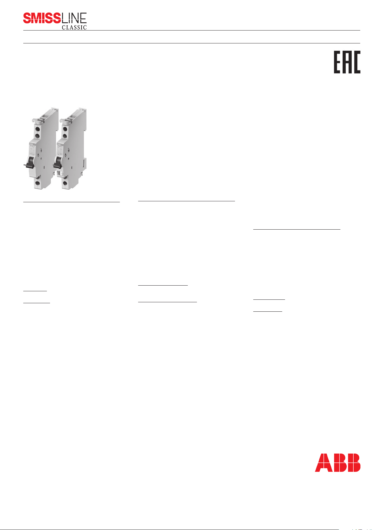
Hilfs- und Signalkontaktblock
Bloc de contact auxiliaire et de signalisation
Auxiliary and signal contact blocks
Contatto ausiliario e di segnalazione
2CCC404012M0104 (20V3500.d)
Par la pression du bouton-test gris,le contact de signalisation
doit s’enclencher. Après chaque déclenchement, il faut
ramener le contact de signalisation en position initiale à
l’aide du bouton Reset de couleur orange.
Mise en place des contacts auxiliares et de
signalisation sur l'appareil:
Disjoncteur de ligne au choix à gauche ou à droite
Interrupteur différentiel 4 pôles à droite
Interrupteur différentiel 2 pôles à droite
Interrupteur différentiel/disjoncteur de ligne à droite
Les contacts auxiliaires et de signalisation pour
profilé support SMISSLINE CLASSIC ne peuvent être
montés sur des systèmes enfichables SMISSLINE.
Montage à droit
Fig. 1 Mettre en place la tige de liaison conformément
à l'établissement du contact de l'interrupteur
différentiel ou du disjoncteur de ligne.
Démontage à droit
Fig. 2
Montage / Démontage à gauche
Fig. 3 / Fig. 4
Guarantee 
The safe operation is assured if the assembly work has
been carried out according to these user instructions.
Safety
Repairs may not be carried out to auxiliary/signal contacts.
Disposal
Faulty products should be treated as hazardous waste and
disposed of in an appropriate manner. National or regional
regulations regarding the disposal of hazardous waste
should be adhered to.
Function description
Auxiliary contacts switch simultaneously with the contacts of
the protective device (actuated manually or automatically)
Signal contacts operate only when the protective device
has electrically tripped due to short circuit or residual
current.
The following can be installed per protective device:
1 auxiliary contact block
or 1 signal contact block
or 2 auxiliary contact blocks
or 1 auxiliary and 1 signal contact block.
Function test
After assembly, the correct functioning of the auxiliary and
signal contact blocks must be checked. Check also, by
means of suitable testing equipment, whether the auxiliary
and signal contacts have switched correctly. For the signal
contact blocks, the orange button must clearly protrude.
When the grey test button is pressed, the signal contact
must operate. After each operation, the signal contact must
be reset, by means of the orange-coloured reset button.
Plazieren von Hilfs- oder Signalkontakte
am Gerät:
Leitungsschutzschalter wahlweise links oder rechts
4poliger Fehlerstromschutzschalter rechts
2poliger Fehlerstromschutzschalter links
Fehlerstrom-Leitungsschutzschalter links
Hilfs- und Signalkontakte SMISSLINE CLASSIC Trag-
schienen-Geräte sind nicht an SMISSLINE Geräte Steck-
systeme anbaubar.
Montage rechts
Fig. 1 Verbindungsstift bei Version Rechts, für Anbau
LS oder FI4, entsprechend entfernen.
Demontage rechts
Fig. 2
Montage / Demontage links
Fig. 3 / Fig. 4
Garantie 
Le bon fonctionnement est garanti lorsque les opérations de
montage décrites dans ces instructions ont été effectuées
correctement et que les contrôles de bon fonctionnement
ont été faits avant et pendant l'exploitation selon la
description donnée dans les présentes instructions.
Sécurité
Ne procéder à aucune sorte de réparation sur les contacts
auxiliaire/signalisation.
Elimination
Les appareils défectueux sont à éliminer en tant que
déchets spéciaux sur les lieux de collecte prévus à cet effet.
Respecter les prescriptions nationales ou régionales.
Description de fonctionnement
Les contacts auxiliaires commutent simultanément
avec les contacts de l'appareil de protection (actionnés
manuellement ou automatiquement).
Les contacts de signalisation commutent en cas de
déclenchement de l'appareil de protection à la suite de
court-circuit ou de courant de défaut.
Par appareil de protection, on peut monter:
1 bloc de contact auxiliaire
ou 1 bloc de contact de signalisation
ou 2 blocs de contact auxiliaires
ou 1 bloc de contact auxiliaire et
1 bloc de contact de signalisation.
Test de fonctionnement
Après le montage, le bon fonctionnement du bloc de
contact auxiliaire et de signalisation doit être testé. Vérifiez
aussi avec un appareil approprié si les contacts auxiliaires
et de signalisation ont commuté. Sur les blocs de contact
de signalisation, le petit bouton orange doit faire clairement
saillie.
Jan. 2016