ABB OVR-15 User manual

—
MEDIUM VOLTAGE PRODUCTS
OVR –Three phase mechanically ganged reclosers
Operator’s quick reference guide for OVR-15, OVR-27 & OVR-38
Product related Safety Notices
The OVR three phase reclosers should be installed within the design limitations as
described on the nameplate and the instructions mentioned in instruction and
maintenance manual. In addition, always follow your company’s safety procedures.
For the safety of the personnel performing maintenance operations on the recloser
or connecting equipment, all components should be electrically disconnected by
means of a visible break and securely grounded.
For detailed information, please refer the instruction manual provided with the
equipment or contact ABB representative.
Copy Right
This document and parts thereof must not be reproduced or copied without written
permission from ABB, and the contents thereof must not be imparted to a third
party, nor used for any unauthorized purpose.
Disclaimer
This document is to be read along with the instruction manual of the product.
This document has been carefully checked by ABB but deviations cannot be
completely ruled out. In case any errors are detected, the reader is kindly requested
to notify the manufacturer. Other than under explicit contractual commitments, in no
event shall ABB be responsible or liable for any loss or damage resulting from the use
of this document or application of the equipment.
A. Powering-up the recloser
It is assumed that the recloser is already installed as per instructions provided in instruction manual. Ensure the cabinet is properly grounded,
that all MCBs are OFF (lower down) and that the service selector switch is in DISCHARGE position.
1. Open the front, upper & lower auxiliary doors of LV cabinet.

OVR –Three phase mechanically ganged reclosers
Page 2 of 6
Operator’s quick reference guide for OVR-15, OVR-27 & OVR-38
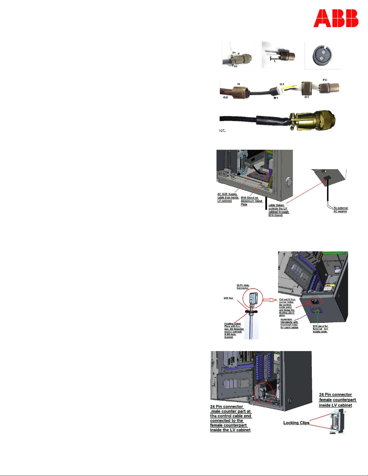
2. Connect external auxiliary power supply to the LV cabinet.
a. Dis-engage the female connector from the male counterpart in the LV
cabinet
b. Connect the external two core auxiliary supply cable to the connector as
indicated in the instruction manual
c. Connect the 2 Pin female connector on the auxiliary supply cable, to its
male counterpart inside the LV cabinet
d. Once engaged, the connection has to be firmly secured by turning &
advancing the circular cap on the female connector over the male
connector
e. Check auxiliary power at 201 - 202 terminal blocks mounted on the back
side of lower auxiliary door.
f. The auxiliary voltage should be as mentioned on rating plate of the LV cabinet.
3. Battery connection
a. While dispatching the equipment from factory, the battery connections
are kept open to reduce internal discharge.
b. Check battery voltage across terminals K20 –J13 and K21 –J13.
c. Voltage in both the cases should be more than 11 V dc. If battery
voltage is less than 11V DC, charge the batteries externally with
external battery charger till voltage across each battery is 12 V dc each
or replace the batteries with new set.
d. After ensuring both battery voltages are more than 11V, check and
firmly connect the 2 pin Green color Male-Female connectors F26 & F27
as per schematic diagram. This will connect the two 12V batteries in
series.
e. Check the voltage across battery terminals to be around 24V
f. Switch ON the MCB: D10-24 MCB for battery
4. Control cable connection to LV cabinet.
a. Insert 24 pin female socket inside the LV cabinet from bottom thru cut
out provided.
b. Fix the floating gland plate (on the cable) to cover the cut out by inserting
4 nos. M6 threaded welded studs on the floating gland plates through the
4 nos. holes provided at the four corners of the cut out and fix with 4nos.
M6 nuts & the M40 nut on the floating gland plate.
c. Connect 24 pin male plug to 24 pin female socket in the LV
5. Put the “Service-Maintenance” rotary switch DS-02 to “Service”
position.
6. Connect communication equipment as applicable.
7. Close both auxiliary doors and switch ON all the MCBs on the
lower auxiliary door.
With the availability of external auxiliary power as per specification,
the LV cabinet will start-up as follows.
a. Relay will startup in approximately 10 Sec.
b. The “Recloser Ready” LED on relay should become green in
approximately 100 Sec.
c. If “Recloser Ready” indication doesn’t turn green after 100
Sec., refer instruction manual for assistance or contact ABB
customer support

OVR –Three phase mechanically ganged reclosers
Page 3 of 6
Operator’s quick reference guide for OVR-15, OVR-27 & OVR-38
B. Quick understanding of recloser LEDs
1. LED indication on Relay
a. Three dedicated LEDs on top of relay display
LED READY START TRIP
ON
Normal operation
A protection function has started and
an indication message is displayed
- If several protection functions start
within a short time, the last start is
indicated on the display
A protection function has tripped and an
indication message is displayed
-The trip indication is latching and must
be reset via communication or by
pressing Clear
-If removed protection function trip
within a short time, the last trip is
indication on the display
OFF
Relay supply voltage
disconnected
Normal operation
Normal operation
FLASHING
Internal fault has occurred or
the IED is in test mode.
Internal faults are
accompanied by an indication
message
A protection function is blocked
- The blocking indication disappears
when the blocking is removed or
when the protection function is reset
b. Eleven programmable LEDs on right side of relay display
Below LEDs are offered with standard recloser solution and may change for specific customer orders. Check as
built drawings for further details.
LED
No.
LED Label Green Red steady Red blinking
1
2
3
4
5
6
7
8
9
10
11
AR status AR is open AR is close
Aux. supply Presence of external Loss of external
auxiliary supply auxiliary supply
AR in progress AR enabled AR in progress
AR Locked out Final LOCKOUT after
reclosing sequence
reached last shot
AR ready ACU is ready & ACU is not ready &/or
manual LOCKOUT manual LOCKOUT is
is not active active
Condition No condition Condition monitoring
monitoring monitoring alarm alarm activated (refer
RER615 technical
manual: 1MRS757817)
Overcurrent OC trip operated
Earth Fault EF trip operated
Hot line tag HLT is activated from HLT is activated
enabled local from remote
Battery status Battery OK Battery fail
Free for user
programming

OVR –Three phase mechanically ganged reclosers
Operator’s quick reference guide for OVR-15, OVR-27 & OVR-38
Page 4 of 6
2. LED indication on ACU
LED Status Description
C. Switches on relay front fascia
D. Handling reclosers during long outages
1. Recloser needs auxiliary power for general application. This power is generally derived from the distribution feeder itself
with the help of control transformer or fed from substation auxiliary source. In case of temporary unavailability of auxiliary
power (few hrs. in a day), the recloser is feed via internal battery bank of the LV cabinet.
2. If battery bank is healthy and in fully charge condition i.e. ≥24 Vdc, for the power outage can be of < 24Hrs. without any
special attention required.
3. If power outage is for more than 24 Hrs OR typically > 10 CO operations after power failure, then it is considered as long
power outage requiring special attention of batteries.
4. During long outages, the batteries might get drained to such a level that it might go into deep discharge stage i.e. battery
bank voltage goes below 18 V.
5. In this situation recloser will not be able to recharge the batteries automatically and external charging may be required.
Such situation might also damage batteries permanently and thus required to be replaced.
6. To avoid such situation, in case of power outage more than 24 Hrs. switch OFF the battery MCB D10-24. After the power is
resume, switch ON the battery MCB D10-24
7. If power outage is more than a month, then charge the batteries on regular interval externally to keep ensure the battery
bank voltage more than 21 VDC.
1
2
3
4
OFF
Blinking
fast
OFF
OFF
Normal condition –ACU ready to
perform operations
Blinking
slowly
Blinking
fast
OFF
OFF
Close operation is not allowed
ON
Blinking
fast
OFF
OFF
Both open and close operations are
not allowed
Don’t care Blinking slowly Boot loader started but the FW is
missed
ON
OFF
ON
OFF
File system error
OFF
OFF
ON
ON
Initial condition at start-up
If the LEDs remain in this condition,
the CPI has not started
ON
ON
ON
ON
This state shows for 3 seconds
indicating ACU can receive FW
upgrades

OVR –Three phase mechanically ganged reclosers
Operator’s quick reference guide for OVR-15, OVR-27 & OVR-38
Page 5 of 6
E. Trouble shooting
(Please read this table in conjunction with the approved/ as built wiring diagram)
Sr.
No.
Trouble /
Malfunction
Indication /
Observation
Possible Causes
Remedy / Trouble Shooting
No voltage across
terminals 201-202 in
LV Unit
- External Auxiliary Power
connection to LV Unit is
loosely connected
- External Auxiliary Power may
be OFF
- Properly connect the Auxiliary
Power supply cable to the plug
inside LV Unit
- Check & correct the status of
the external power supply.
1
Auxiliary Power
failure
Voltage is present
across terminals 201-
202 in LV unit but
cubicle light & aux.
power outlet,
heater(s), do not
have power.
MCB for Auxiliary Supply Mains is
OFF
Switch ON the MCB for Auxiliary
Supply Mains
Individual MCBs for cubicle light
& aux. power outlet, heater(s) are
OFF
Switch ON the MCBs for cubicle
light & aux. power outlet ,
heater(s)
2
ACU/RER615
does not power
up even after
main Aux. MCB
is ON & Aux
Supply is
available for
more than 60s
No LEDs
(RED/GREEN)
glowing on ACU
MCB for ACU is OFF
Switch ON the MCB for ACU (
MCBs D10-31 & D10-24)
No LEDs on relay HMI
glow and LCD screen
of RER615 does not
light up
One or more blinking
RED LED on ACU
Manual Lock out activated.
Emergency manual trip (k69)
handle has been operated and is
locked in operated/tripped
position.
Reset the emergency manual trip
handle & release the manual lock
out
Control cable between LV & HV
units loose / not connected
Connect and secure the control
cable between HV & LV units
3
Recloser (AR) is
NOT ready ;
OPEN & CLOSE
operations not
possible from
RER615 or from
remote
AR Ready LED on
Relay glowing RED
Battery temperature sensor
connection to ACU is loose/not
connected
Check and secure connection of
battery temperature sensor to
ACU through male - female
connectors provided.
Capacitor not sufficiently
charged
- Put selector switch in
DISCHARGE position
- Allow capacitors to fully
discharge (follow warning label
text guidelines)
- Check capacitor connections to
ACU for loose contact and
correct polarity as per wiring
diagram
- Check the capacitor health;
replace capacitors if needed
Wrong recloser
ON/OFF status on
SLD of RER615 HMI
The wiring of the 52a/b aux. limit
switch may be loose or wrong
(52a/b aux. limit switch is
mounted in HV unit)
Check, secure and correct the
wiring of 52a/b aux. limit switch
as per approved /as built
schematic

OVR –Three phase mechanically ganged reclosers
Operator’s quick reference guide for OVR-15, OVR-27 & OVR-38
Page 6 of 6
Sr.
No.
Trouble /
Malfunction
Indication /
Observation
Possible Causes
Remedy / Trouble Shooting
(mismatch with
mechanical ON/OFF
indicator/ LEDs on
RER615)
-OR-
Relay LED or SLD on
relay LCD shows both
( ON/OFF) or no
status
The mounting/setting of the
52a/b aux. limit switch may be
wrong/ loose
-OR-
The 52a/b aux .limit switch is
faulty/ damaged
(52a/b aux. limit switch is
mounted in HV unit)
- Check and correct the
mounting/setting of the 52a/b
aux. limit switch
- Replacement of the 52a/b
switch may be needed if found
faulty/damaged
- Contact ABB Customer Service
Group
4
Recloser (AR) is
Ready but
CLOSE
operation is not
possible from
RER615 Local
HMI or remote
SYN CHECK LED (if
applicable) on relay
The phase sequence of the MV
power connections on both sides
of the recloser are not matching
to each other
Check & correct the phase
sequence of the MV power cable
connections to the recloser
terminals
HMI turns RED
Synchronizing and Energization
check conditions are not being
satisfied as per settings of
SECRSYN function block.
Check the system voltage
parameter and network status
MCB for Battery is OFF
Switch ON the MCB for Battery
5
Battery Failure
Battery Status LED
on relay HMI turning
RED
Battery connections to ACU
loose or with wrong polarity
Check, correct and secure battery
connections to ACU with correct
polarities
Battery unhealthy (Battery may
have undergone deep discharge;
excessive temperatures; or
exceeded working life)
Check battery health and replace
the battery if needed
ACU is taking more than 20
seconds to become ready
Follow steps of clause 3.0 above
6
Condition
monitoring
alarm activated.
This is proactive
alarm about
recloser
condition which
may need
attention in
near future
Condition monitoring
alarm on relay HMI
turning RED
Out of the rated life of 10000 CO
operations , 9000 CO operations
completed and last 1000 CO
operations are remaining
Contact the nearest ABB
Customer Service Group for
further advice
Recloser has completed 22 no. of
open operations on rated fault
current
Recloser is in "inactive " (no
close/open operations) stage for
more than 2000 days ; after the
latest ON/OFF operation while
LV unit powered ON
The data and illustrations are not binding. We reserve the right to modify the contents of this document without prior notice following technical and product developments.
©Copyright 2021 ABB. All rights reserved
Doc ID: 1VYN401790-035© June 2021 ABB. All rights reserved
—
ABB India Limited
Plot 34 & 79,
MIDC Estate, Satpur,
Nashik, MH 422007, India
Phone: +91 253-2201-200
Fax: +91 253-2351-260
new.abb.com/medium-voltage
—
ABB SAU
Norberto Lopez 3600
El Jagüel, Buenos Aires
B1805ABT, Argentina
Phone: +54 11 5984 3560
—
ABB de México S.A. de C.V.
Av. Central 310 Parque
Logístico
San Luis Potosí
78395, México
Phone: +52 55 8525 9486
—
ABB Inc.
655 Century Point
Lake Mary, Florida
32746, USA
Phone: +1 407 732 2000
Email:
Other manuals for OVR-15
4
This manual suits for next models
2
Table of contents
Other ABB Industrial Equipment manuals
Popular Industrial Equipment manuals by other brands

Graco
Graco ProMix PD2K Installation

OP
OP UNISPEED US-FL/01 Use and maintenance manual

LEGRAND
LEGRAND Solarfective SF-T4 installation instructions

Worthington
Worthington Amtrol Surge-Trol SPT-1 Installation & operation instructions

Tsubaki
Tsubaki TGM Series installation manual

Siemens
Siemens SIRIUS 3RV1913 operating instructions