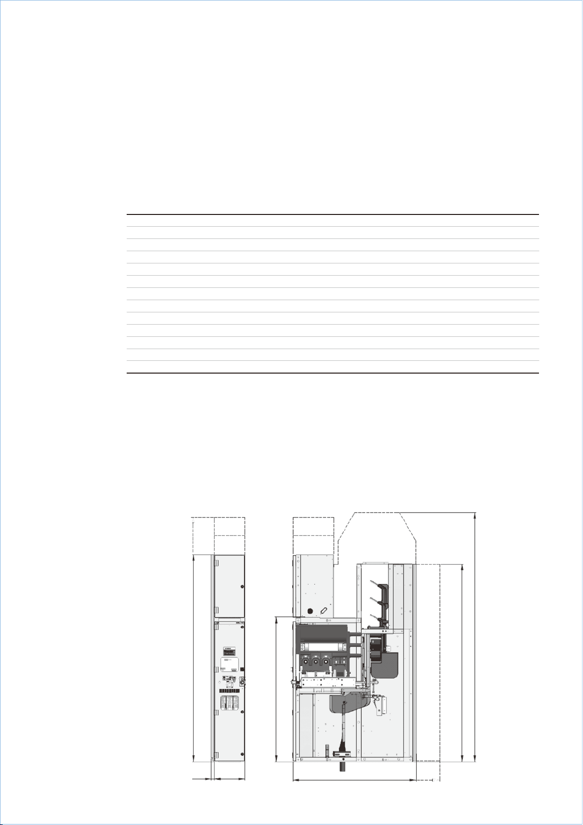
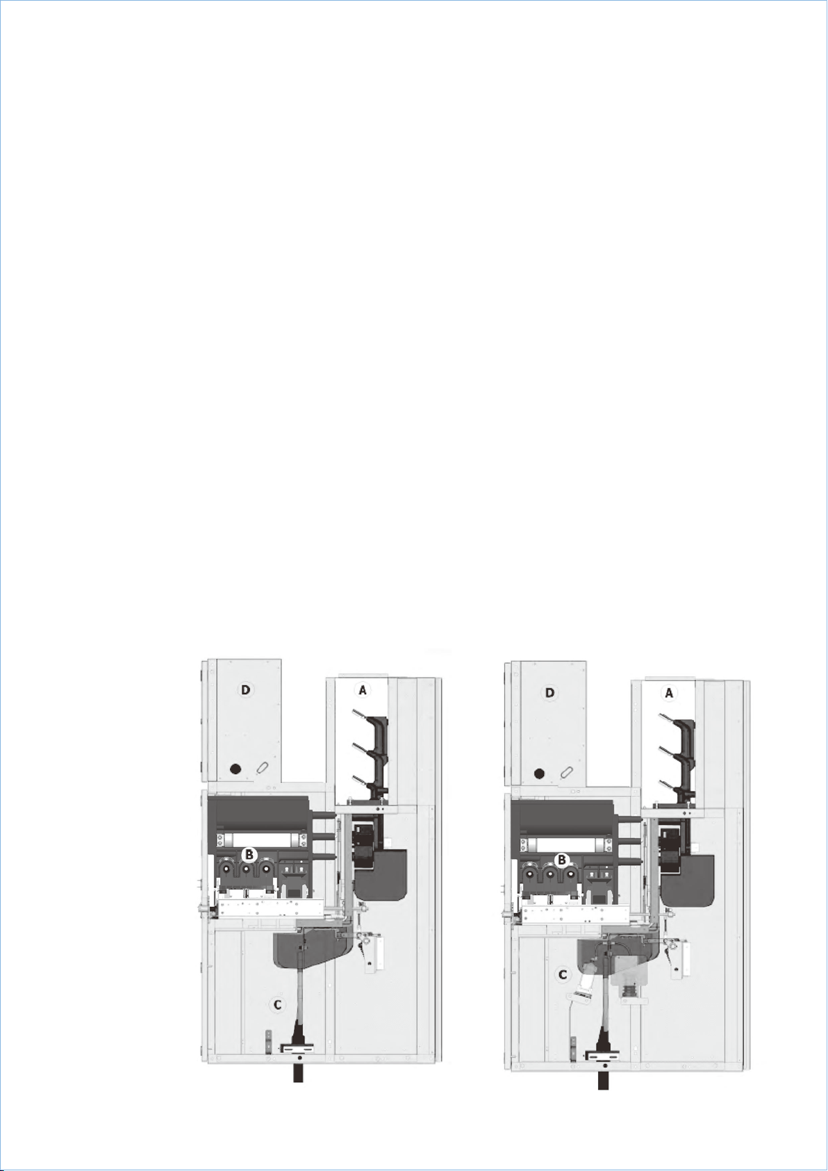
4.1 Basicstructure
The basis for the UniGear ZVC panel is theoutgoing
feeder panel with fused vacuum contactor of a
horizontal withdrawable design. It is divided into
busbar compartment A, fused vacuum contactor
compartment B, cable compartment C and low
voltage compartment D for the secondary
equipment. Apart from this, there are variants for
other operatingneeds. 4/1 to 4/3 shows examples
of possible configuration of a panel variant for
direct-on-line motor starters including electrical
equipment. Panels can be coupled in combinations
to provide variants for reversing motor starters,
twospeed motor starters, autotransformer motor
starters and reactor motor starters.
Further details about installation and equipping
the switchgear can be obtained from the order
documents.
4.1.1 Busbar compartment (4/12)
The busbars have a flat cross-section made of
copper and are laid in sections from panel to
panel. For higher rated currents (up to 4000 A),
the busbars have a D-shaped cross-section.
According to the current rating,either single or
double configuration is used. They are held by
a resin encapsulated branch conductor. No special
connection clamps are needed. No additional
support is necessary to withstand therated
short circuit current of the busbar system.
Busbars are insulated by means of shrink-on
Raychem sleeves. The bolt connections are without
any covers unless it is a specific requirement of
the customer order document.
4.1.2 Fused contactor compartment (Figures
4/10, 4/12, 4/13and4/14)
The fused contactor compartment contains all
the necessary equipment for removal/insertion
and connection/disconnection operation of the
withdrawable fused contactor. Like the busbar
compartment, it is metallically partitioned on
all sides.
The fused contactor compartment B includes
guiderails for the withdrawable fused contactor.
The withdrawable fused contactor is anchored to
the cubicle with a truck lock operated by a double
bit key. Thetruck is moved between ISOLATED
and SERVICE position by a racking screw.
Self-aligningtulip contacts are located in epoxy
resin spout bushings behind a metal partition
plate.Automatic metal shutters, coveringthe
busbar and cable spout bushing openings, are
also included.
The shutters are opened by means of actuating
rods when the withdrawable fused contactor
moves to the SERVICE position, and are closed
when the withdrawable fused contactor returns
to theISOLATED position. In the ISOLATED position
the withdrawable fused contactor is separated
by metal partitioning from the main current
circuit.
Secondary control wiring contacts are automatically
connected via theplug on the rear of thetruck,
when the truck is installed in the cubicle and
thetruck lock operated.
The switching operations are carried out with
the door closed. The FUSE BLOWN indicator and
ON/OFF mechanical indicator on the contactor
can be observed through an inspection window. A
device for emergency manual opening of a latched
contactor in the SERVICE position is located below
the inspection window.
4.1.3 Withdrawablefused contactor (Figures
4/10, 4/12, 4/13and4/14)
The withdrawable fused contactor consists of a
vacuum contactor, type V7/ZVC, and tag type HRC
HV fuses housed in an epoxy resin monoblock
mounted on a chassis. Contact spouts are
incorporated in the monoblock to establish
connection between thewithdrawable fused
contactor and the tulip contacts in the panel.
The secondary contacts plug is automatically
connected when the contactor is inserted into
the contactor compartment.
The truck is moved manually between theSERVICE
and ISOLATED positions with the front door closed
by a handle engaged in the rackingspindle. SERVICE
and ISOLATED positions are monitored electrically
by means of auxiliary switches.
The earthing connection between the withdrawable
fused contactor and the panel is established by
its rollers and travel rails, which are bolted to
the panel.
Optional Control VT, with primary fuses, is mounted
on the chassis and is connected toterminals
on the load side of the HV fuses.
4.1.4 Cable connection compartment (Figures
4/12and 6/20)
The cablecompartment contains current
transformers, earthing switch, and cable
terminating module. Where specifically ordered,
the compartment can also contain surge arresters,
capacitive insulators and zero sequence current
transformer.
The typeZVCE7 fault-making earthingswitch is
manually operated by handle, with the front door
closed. Its switching position will be indicated
both mechanically and electrically by means of
the auxiliary switch.The physical position of
the moving contacts can beviewed through a
window in the front door.
The compartment is suitable for connectingup
to 1x240 mm2 3-core cable or 2x150 mm23-core
cables on copper tags separated by epoxy resin
phase barriers on the cable terminating module.
Complex combinations of cable type and size,
zero sequence CT, cable clamps/glands,surge
arresters and capacitive insulators must be
decided at thetimeof manufacturer.
4.1.5 Low voltagecompartment (Figures 4/12,
6/19)
The compartment contains control and protection
equipment suitable for both conventional or
microprocessor control technology.
The height of the low voltage compartment is
665/865/1060 mm.
If thesecondary devices are not intended for
door installation, they are mounted on special
metal strips. They enable any subsequent
changes tothe wiring.
In the lower part of the low voltage compartment,
there are rows of terminal strips. There is a bushing
for sliding in the interpanel wires at theside of
the low voltage compartment.
Secondary wiring inside thepanel is inaduct
on theright side of the panel. The left side of
the panel is for the external wiring. The wiring
is protected by a steelcover.
—
4 Panel design and equipment
PANEL DESIGN AND EQUIPMENT 9