manuals.online logo
Brands
  1. Home
  2. •
  3. Brands
  4. •
  5. ABB
  6. •
  7. Inverter
  8. •
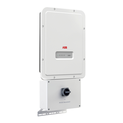
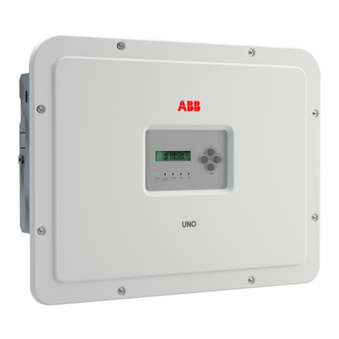
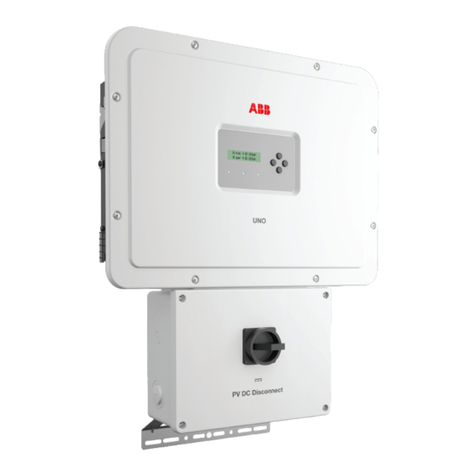
  9. ABB UNO-DM-6.0-TL-PLUS User manual

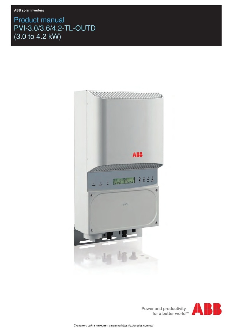
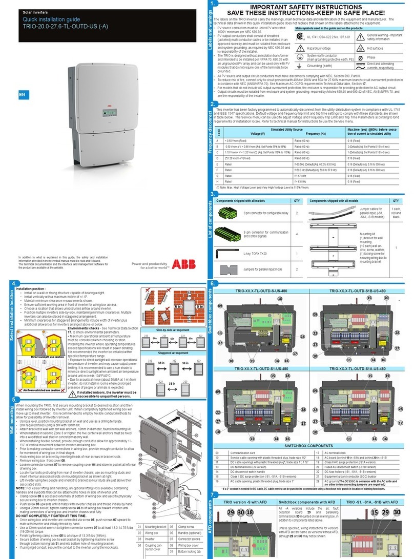
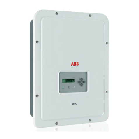
ABB UNO-DM-6.0-TL-PLUS User manual

In addition to the information given below, it is mandatory to read and observe the safety information
and installation instructions shown in the installation manual. The technical documentation and the
interface and management software for the product are available on the website.
The equipment must be used in accordance to what is described in this Quick Installation Guide.
Otherwise, the protections guaranteed by the inverter may be affected.
Quick Installation Guide
UNO-DM-6.0-TL-PLUS
(6.0 kW)
ABB solar inverter
1.
Labels and Symbols
Models and Inverter Components
2.
Lifting and transportation
3.
EN
Assembly instructions
6.
Choice of the place of installation
4.
Supplied component list
5.
8.
Input connection (DC) and input congurations
7.
Opening the cover
The labels on the inverter show the markings, main technical data and the identication of the equipment and of the manufacturer.
The below labels are intended as example only: in fact other models are available.
A4 1:1 1/1
Regulatory Label of UNO-DM-6.0-TL-PLUS-SB-G
XLP.V2R03.0AL AA
A.Statuti
A.Butini
G.Fiesoli
C.Granci
07/09/2017
07/09/2017
07/09/2017
07/09/2017
Pantone
Process Cyan C Process Yellow C
LABEL MATERIAL: 3M type 7331 (UL R/C, PGJI2)
INKS: Refer to UL File MH16411
LABEL CONTENT: Fixed as shown in the picture
SIZE: 68 mm (height) x 75 mm (width)
MODEL:
UNO-DM-6.0-TL-PLUS-SB-G
V
dc max
V
acr
IP65
-25 to +60 °C
-13 to +140 °F
(1): @ 45°C amb. (2): Over/Under excited
600 V
90 - 580 V
2 x 20 A
160 - 480 V
2 x 24 A
230 V 1Ø
50 Hz
6000 W
(1)
6000 W
(1)
0.1 - 1
(2)
6650 VA
I
dc max
V
dc MPP
V
dc, Full Power
I
sc max
f
r
A
dj cosφ
P
acr (cos = ±0.9)
φ
P
acr (cos = 1)φ
S
max
30 AI
ac max
5 minutes
INVERTERSOLAR
www.abb.com/solar
Made in Italy
DIN V VDE V 0126-1-1
PROTECTIVE CLASS: I
All material us ed and finished product, must meet the requirements of the current RoHS rec ti
ive 2002/95/EC.
Title
Issued
Modified
D
D
esign approved
Elec. Eng. approved
Mfg. approved
Size Scale Dim. in mm Sheet Drawing No. Revision
© Copyright 2017 Power-One Italy Spa. All rights reserved. Reproduction, use or disclosure to third parties without express written authority is strictly forbidden.
UNO-DM-X.X-TL-PLUS
P/N:PPPPPPPPPPP
WO:XXXXXXX
SO:SXXXXXXXX Q1
SN:YYWWSSSSSS WK:WWYY
Product Label (In case of a service password
request, it is necessary to have the serial number
available (SN: YYWWSSSSSS))
Wireless Identification Label (The label is divided in
two separate parts by a dashed line; take the bottom part
and apply it on the cover of this quick installation guide)
Regulatory Label
The labels placed on the equipment absolutely MUST NOT be removed, damaged, dirtied, hidden, etc.
In the manual, and/or in some cases on the equipment, the danger or attention zones are indicated by signs, labels, symbols or icons.
Obligation to consult the
manual
General warning - Important
safety
information
Dangerous voltage Hot parts
IP65
Degree of protection of the
device
Temperature interval
Without isolating
transformer
Direct and alternating
current respectively
Positive and negative pole
of the input voltage (DC)
Obligation to use protective
clothing and/or personal
protective equipment
Point of connection of the
protective ground
Discharge time of the
stored energy
10
The following variants are available (sufx could be combined):
- Models with “B” sufx (e.g. UNO-DM-6.0-TL-PLUS-B). Models equipped with Wireless communication.
- Models with “S” sufx (e.g. UNO-DM-6.0-TL-PLUS-S). Models equipped with DC disconnecting switch.
- Models with “E” sufx (e.g. UNO-DM-6.0-TL-PLUS-E). Models equipped with Wireless communication and Accessory Board equipped with Ethernet board
(UNO-DM-PLUS-COM Etherner KIT).
- Models with “X” sufx (e.g. UNO-DM-6.0-TL-PLUS-X). Models equipped with Accessory Board (UNO-DM-COM KIT).
- Models with “G” sufx (e.g. UNO-DM-6.0-TL-PLUS-G). Models equipped with AC connection with cable gland and terminal block.
Main components
01
Bracket
02
Lock spring
03
Heatsink
04
Anti-condensation valve
05
Front Cover
06
LED panel
07
Display
08
Keypad
09
DC Input Connectors
10
AC cable gland
11
Wireless antenna connector
12
DC Input terminal block
13
AC Output terminal block
16
DC disconnect switch
(only -S models)
18
UNO-DM-COM KIT card
(optional)
19
External ground connection
20
Service cable gland
Components supplied with the inverter Quantity
Bracket for wall xing 1
M25 Cable glands 1
Wireless antenna 1
Cable with faston isolated for the
conguration of the input channels
in parallel
1 + 1
(Spare part) T20 screw for front cover 1
Components supplied with the inverter Quantity
M5x10 screw for the external ground
connection 1
M5 contact washers for the external
ground connection 2
M5x10 Wall bracket locking screws
(optionally mounting, to be used if
required)
2
M5 Wall bracket locking washers
(Optionally mounting, to be used if
required)
2
Inadditiontowhatisexplainedinthis guide, thesafety and installationinformationprovided inthe installationmanual mustbe read andfollowed.
Thetechnicaldocumentationandtheinterfaceandmanagementsoftwarefor theproduct are availableat the website.
XXXXXXXXXXXXXXXXXXX
XXXXXXXXXXXXXXXXXXX
ABBsolarinverters
Technical documentation 1
Transportation and relocation
The transportation of the device, in particular via land transportation, must be made with adequate
means and ways to protect the parts from violent impacts, humidity, vibrations, etc.
Lifting
The means used for lifting must be suitable to bear the weight of the equipment.
Weight of the equipment components
Model Weight
All models 20.5 kg / 45.2 lb
Unpacking and inspection
The packaging components must be removed and disposed of according to the applicable
regulations of the country where the device is installed.
Upon opening the packaging, check the integrity of the equipment and verify that all the
components are present.
If you notice defects or deterioration, stop the operations and call the carrier, as well as inform
ABB Service immediately.
Please keep the packaging in the event it has to be returned; the use of inadequate packaging will
void the warranty.
Always store the Quick Installation Guide, all the supplied accessories
and the AC connector cover in a safe place.
Do not open the inverter in case of rain, snow or
high humidity (>95%). During the installation, do
not place the inverter with the front cover
05
facing
the ground.
Install the inverter by following this procedure:
• Place the bracket
01
level on the wall and use it as a drilling
template.
• The selection of the appropriate number and distribution of the
anchors is the responsibility of the installer. The choice must
be made according to the type of wall, frame or other type of
support, and should be sized considering a total load of more
than 4 times the weight of the inverter (total 4x20.5=82 kg
total). Depending on the type of anchor chosen, drill the holes
required for the xing of the bracket (Figure
A
).
• Fix the bracket to the wall or structure.
• Carefully lift the inverter and hook it onto the bracket by
inserting the two supports in the slots on the inverter (Figure
B
).
• Proceed to anchor the inverter to the bracket by pressing the
lower part toward the wall or structure until the two springs on
the bracket set the inverter in position (Figure
B
).
• Install wireless antenna by screwing it into the dedicated
connector located on the bottom part of inverter
11
(Figure
C
).
WARNING! ELECTRIC SHOCK HAZARD! Hazardous voltages may be present inside the
inverter. The access to the internal zones of the inverter must be carried out after a
minimum waiting time of 5 minutes since the inverter was disconnected from the grid
and from the photovoltaic generator.
• The main connections are made on the lower part (outside) of the inverter. To install the accessories and make the
necessary connections, unscrew the 8 screws using a TORX T20 key and open the front cover
05
; while removing
the screws, pay special attention since additional screws are not supplied.
Caution! It is necessary to hold the front cover during the removal of screws to avoid the cover
falling (the front cover is not secured to the inverter’s chassis).
• After making the connections, close the cover by tightening the 8 screws on the front, while respecting the sequence
and tightening torque (2.5 Nm).
1
86
57
32
4
05
07
06
13
12
01
03
08
02
03
01
16 09 04 10 20
11
18
19
Place and position of installation
- Refer to the technical data for the verication of the environmental conditions to be
met.
- Do not install the inverter where it is exposed to direct sunlight. If necessary, use
protection that minimizes the exposure, especially for ambient temperatures above
40°C/104°F.
- Do not install in small unventilated spaces where the air cannot circulate freely.
- Always ensure that the airow around the inverter is not blocked to prevent
overheating.
- Do not install near ammable substances (minimum distance 3 m/10 ft).
- Do not install on wooden walls or other ammable substances.
- Do not install inside residential premises or where a prolonged presence of people
or animals is planned, due to the acoustic noise that the inverter produces during
operation. The noise emission value is strongly inuenced by the installation
location (e.g. type of surfaces around the inverter, general properties of the room,
etc.) and the quality of electricity supply.
- Install on a solid wall or structure that is suitable to support the weight of the
equipment.
- Install in an upright position with a maximum inclination as shown in the gure.
- Respect the minimum distances indicated. Choose a location that allows enough
space around the unit to allow easy installation and removal of the equipment from
the mounting surface.
- Where possible, install at eye level for easy viewing of the display and the LEDs.
- Install at a height that takes into account the weight of the equipment.
- When installing multiple inverters, position the inverters side by side while
maintaining the minimum distances (measured from the outer edge of the inverter);
if the space available does not allow this provision, position the inverters in a
staggered layout, as indicated in the gure, in order to make sure that the heat
dissipation is not affected by the other inverters.
- All installations at altitudes above 2,000 m/6,500’ must be assessed on a case by case basis with ABB Service to determine the proper derating of the input
parameters.
The nal installation of the inverter must not compromise the access to any disconnection devices located outside.
Refer to the warranty conditions to evaluate the possible exclusions related to an improper installation.
15
cm
10 cm 10 cm
20
cm
5° MAX5° MAX
NONO
Check the correct polarity of the input strings and the absence of earth leakages of the PV generator. When the PV panels are exposed
to sunlight, they provide a continuous voltage (DC) to the inverter. Access to the internal inverter zones must be carried out with the
equipment disconnected from the grid and from the PV generator.
Caution! The inverters referred to in this document are WITHOUT AN ISOLATION TRANSFORMER (transformer-less). This type involves the
use of PV panels of an isolated type (IEC61730 Class A Rating) and the need to maintain the PV generator oating with respect to earth; no
generator pole must be connected to the ground.
If multiple strings are connected to the same input, they must have the same type and number
of panels in series. ABB also recommend they have the same orientation and inclination.
• Observe the maximum input current with respect to quick-coupling connectors. Refer to “String inverters -
Product manual appendix” document available on the site www.abb.com/solarinverters, to nd out the make and
model of the quick-coupling connector used on the inverter. Depending on the model of the connectors installed
on your inverter, it will be necessary to use the same model for the corresponding counterparts (by checking the
manufacturer’s website or via ABB for the compliant counterpart).
The use of non-compliant counterparts with respect to the quick-coupling connectors models
present on the inverter, may cause serious damage to the unit and result in the immediate
loss of warranty
• Connect the DC input, always checking the tightness of the connectors.
• Versions of the inverter which are equipped with two independent input channels (i.e. dual maximum power point tracker, MPPT), can be congured as parallel
(i.e. single MPPT).
Conguring Input Mode to Independent (default conguration)
This conguration is set at the factory and involves the use of the two input channels (MPPT) in
an independent mode. This means that the jumpers (supplied) between the positive and negative
poles of the two DC input channels
12
must not be installed, and that the independent channel
mode should be set during the commissioning phase, in the dedicated section of the internal
webserver “SETTINGS > SETUP DC SIDE > INPUT MODE” or through the inverter display menu
“SETTINGS> INPUT MODE”.
DC INPUTS
-IN1 -IN1 +IN1 +IN1 +IN2 +IN2-IN2 -IN2
12
Conguring Input Mode to Parallel
This conguration involves the use of the two input channels (MPPT) connected in parallel. This
means that the jumpers (supplied) between the positive and negative poles of the two DC input
channels
12
must be installed, and that the parallel channel mode should be set during the
commissioning phase, in the dedicated section of the internal webserver “SETTINGS > SETUP
DC SIDE > INPUT MODE” or through the inverter display menu “SETTINGS> INPUT MODE”.
APPLY HERE
THE WIRELESS
IDENTIFICATION LABEL
A
B
C
12.
Commissioning
11.
Instruments
BCM.V2R03.0AP_AA_UNO-DM-6.0-TL-PLUS-Quick Installation Guide EN-RevA
EFFECTIVE 01-11-2017
© Copyright 2017 ABB. All Rights Reserved.
Specications subject to change without notice.
9.
Line cable and protective devices
10.
Output connection (AC)
13.
Display menu structure
→
Features and Technical Data
14.
Features and Technical Data
Protection switch under load (AC switch) and sizing of the line cable
To protect the AC connection line of the inverter, we recommend the installation of a protection device against overcurrent and earth leakages with the following
features:
UNO-DM-6.0-TL-PLUS
Type Circuit breaker with differential magnetic-thermal protection
Nominal voltage 230 Vac
Nominal current 40.0 A
Magnetic protection feature B/C
Number of poles 2
Type of differential protection A/AC
Differential sensitivity 300 mA
ABB declares that the ABB high frequency inverter without a transformer are not manufactured to inject continuous currents of ground fault, and therefore, the
differential installed downstream of the inverter, type B according to IEC 60755/A 2, is not required.
Characteristics and sizing of the line cable
The cable should be three-pole. The section of the AC line conductor must be sized in order to avoid
unwanted disconnections of the inverter from the distribution network due to high impedances of the
line that connects the inverter to the point of supply of electricity.
Line conductor cross-section Maximum length of the line conductor (m)
4 mm28 m
6 mm212 m
10 mm220 m
16 mm230 m
The values are calculated in nominal power condition considering:
1. a power loss along the line of not more than 1%.
2. copper cable used, with HEPR rubber insulation and placed in open air
Contact us
www.abb.com/solarinverters
LED and KEYS, in various combinations, may display the status conditions or perform complex actions to be explored by consulting the product manual.
LEDs
06
POWER
Green Solid when the inverter is working correctly. Flashes when checking the grid or if
there is insufcient sunlight.
COMM
STATUS Multicolor
Operation status of wireless communication line.
ALARM Yellow The inverter has detected an anomaly. The anomaly is shown on the
“EVENTS” section of the internal webserver and on the display.
RSSI Multicolor Quality of the wireless communication signal.
GFI Red Ground fault on the DC side of the PV generator. The error is shown on the
“EVENTS” section of the internal webserver and on the display.
Keys
08
ESC Used to access the main menu, to go back to the previous menu or to go back to the previous digit to be edited.
UP Used to scroll upwards the menu options or to shift the numerical scale in ascending order.
DOWN Used to scroll downwards through the menu options or to shift the numerical scale in descending order.
ENTER Used to conrm an action, to access the main menu or the submenu for the selected option (indicated by the > symbol) or to switch to the next digit to edit.
UNO-DM-6.0-TL-PLUS
Input
Absolute maximum input voltage (Vmax,abs)600 V
Input activation voltage (Vstart)200 V
(adj. 120...350V)
DC input voltage operating range (Vdcmin...Vdcmax)0.7xVstart...580 V (min 90 V)
Rated input DC voltage (Vdcr)360 V
Rated input DC power (Pdcr) 6200 W
Number of independent MPPTs 2
Maximum Input power for each MPPT (PMPPTmax) 4000 W
DC input voltage range (VMPPT min ... VMPPT max) with parallel conguration of
MPPT at Pacr 160...480 V
Numbe DC power limitation with parallel conguration of MPPT
Linear derating from Max to 500W [480V≤VMPPT≤580V]
DC power limitation for each MPPT with independent conguration of MPPT
at Pacr , max unbalance example
4000 W [220V≤VMPPT≤480V]
the other channel: Pdcr-4000W [120V≤VMPPT≤480V]
Maximum DC input current (Idc max) / for each MPPT (IMPPTmax)40.0 A / 20.0 A
Maximum return current (AC side vs DC side) < 5 mA (In the event of a fault, limited by the external protection on the AC circuit)
Maximum short circuit current (Isc max) / for each MPPT 50.0 A / 25.0 A
Number of input DC connection pairs for each MPPT 2
DC connection type Quick t PV connector (1)
Type of PV panels connected in input in accordance with Standard IEC 61730 Class A
Input protection
Reverse polarity protection Yes, from a current limited source
Input overvoltage protection for each MPPT- Varistors Yes
Photovoltaic array insulation control According to local standard
DC disconnect switch characteristics (version with DC disconnect switch) 600 V / 25.0 A
N
L
Max 16 mm²
x:
18 mm
Ø13÷21mm
x
COMM
STATUS
RSSI
080706
UNO-DM-6.0-TL-PLUS
Output
AC connection type Single phase
Nominal output AC power (Pacr@cosφ=1) 6000 W
Maximum output AC power (Pac max@cosφ=1) 6000 W
Maximum apparent power (Smax)6650 VA
Nominal output AC voltage (Vacr)230 V
Output AC voltage range (Vacmin...Vacmax)180...264 Vac (3)
Maximum AC output current (Iac max)30.0 A
Maximum fault current
<40 A rms (100 ms)
Short circuit current contribution 40.0 A
Inrush current Negligible
Nominal output frequency (fr) 50 Hz (4)
Output frequency range (fmin...fmax)47...53 Hz (4)
Nominal power factor and adjustability interval > 0.995; 0.1 – 1 Over/Under excited
Total harmonic current distortion < 3.5%
AC connections type
Screw terminal block, Cable Gland M32
Output Protection
Anti-islanding protection According to local standard
Maximum external AC overcurrent protection 40.0 A
Output overvoltage protection - Varistor 2 (L - N / L - PE)
Operational Performances
Maximum efciency (η
max
)97.4%
Weighted efciency (EURO/CEC) 97.0% / -
Power threshold of the power 8.0 W
Nighttime consumption < 0.4 W
Communication
Embedded Communication interface Wireless (5)
Optional Communication interface RS485, Ethernet, ZigBee (6)
Embedded Communication protocol ModBus TCP (SunSpec)
Optional Communication protocol ModBus RTU (SunSpec), Aurora protocol
Commissioning tool Web user interface, Display, Aurora Manager Lite
Firmware update capabilities Locally and remotely
Monitoring Plant Portfolio Manager, Plant Viewer, Plant Viewer for Mobile (7)
Environmental
Ambient temperature range -25...+60°C /-13...140°F
Ambient temperature derating above
45°C/113°F
Relative humidity 0...100% condensing
Typical noise emission pressure < 50 dB(A) @ 1 m (10)
Maximum operating altitude without derating 2000 m/6560 ft
Classication of environmental pollution degree for the external environment 3
Environmental category Outdoor
Physical
Environmental protection degree IP 65
Cooling system Natural
Dimensions (H x W x D) 418 mm x 553 mm x 180 mm/16.5” x 21.8” x 7.1”
Weight 20.5 kg / 45.2 lb
Mounting system Wall brackets
Overvoltage category in conformity with IEC 62109-1 II (DC input) III (AC output)
Safety
Isolation level Transformerless (TL)
Certications CE, RCM
Safety class I
Safety and EMC standard EN 50178, IEC/EN 62109-1, IEC/EN 62109-2, AS/NZS 3100, EN 61000-6-1, EN 61000-6-3,
EN 61000-3-11, EN 61000-3-12
Grid standard (9) (check your sales channel for availability) CEI 0-21, DIN V VDE V 0126-1-1, G59/3, EN 50438 (not for all national appendices), RD
1699, ITC-BT-40, AS 4777, C10/11, IEC 61727, IEC 62116
1. Refer to the document “String inverter – Product Manual appendix” available at www.abb.com/solarinverters to know the brand and the model of the quick t connector.
3. The AC voltage range may vary depending on specic country grid standard.
4. The Frequency range may vary depending on specic country grid standard.
5. As per IEEE 802.11 b/g/n standard.
6. Availble for custom version only.
7. Plant Viewer per Mobile availble remotely only, not for local commissioning.
9. Further grid standard will be added, please refer to ABB Solar page for further details.
10. @ Pure sine wave condition.
Note. The features that are not specically mentioned in this data sheet are not included in the product
The ABB inverters are equipped with a display
07
, consisting of 2 lines of 16 characters each, which can be used to:
- View the operating status of the inverter and the statistical data
- View service messages for the operator
- View alarm and fault messages
- Change the inverter settings
During the normal operation of the inverter, the display cycles through the GENERAL INFORMATION. This information relates to the input and output parameters
and the inverter identication parameters. By pressing ENTER it is possible to block automatic scrolling on a screen so that it is locked to this screen.
Press ESC to access the main menu, which is structured as follows:
> Settings
> Measures
> Set time
> Set cash
> Set RS485 com
> Country Select
> New password
Inverter
> Statistics
> Settings
> Vstart
> Input mode
> Input UV delay
> Service
> Info
> Part No.
> Serial No.
> Firmware
> Remote ON/OFF
> MPPT scan
> Power Limit
> Reactive Power
> Autotest
> Alarms
> Lifetime
> Partial
> Today
> Last 7 days
> Last 30 days
> Last 365 days
> User Period
Display
> Settings
> Backlight
> Contrast
> Language
WLAN Logger
> Settings
> Serial No.
> View IP
> View Mode
> Restore AP
> Info
> Part No.
*
Inverter OK
Mon 01 Jan 12:00
E-day XXX Wh
$-day X.XX EUR
E-tot X kWh
E-par X kWh
Pout XXX W
Psetpoint XXX %
Cos-phi fixed
Cosp X.XXX
Pin2 XXX W
Pin1 XXX W
Vin2 XXX V
Iin2 X.X A
Vin1 XXX V
Iin1 X.X A
Igrid X.X A
Fgrid XX.XX Hz
Ppk XXX W
Ppkday XXX W
Vgrid XXX V
Riso XX.X M©
Ileak X.XXXX A
Vbulk XXX V
Vbulk_m XXX V
System
*
Display menu may differ from previous structure depending on rmware installed in the inverter. Firmware version can be displayed accessing to the
display menu Inverter > Info > Firmware.
Refer to the manual for details regarding use and functions available in the menu and for details regarding alarm and fault messages.
Caution! Before performing the operations described below, make sure that you have properly disconnected the AC line downstream of
the inverter!
For the grid connection of the inverter, 3 connections are needed: ground, neutral and phase. In any case, the earth connection of the inverter is mandatory.
The connection of the network cable to the inverter is performed by means of the AC cable gland
10
and the dedicated AC output terminal block
13
, by doing
the following:
- Strip 18 mm of sheathing from the AC grid connection cables
- Plug the AC line cable into the inverter, passing it through the AC cable gland
10
The procedure for opening the contacts of AC output terminal block
13
and tightening
cables is as follows:
1) Insert a at screwdriver in the slot behind the contacts until the clamp opens.
2) Insert the cable in the clamp with the screwdriver inserted in the slot.
3) Remove the screwdriver and check the tightness.
- Connect the protective earth (yellow-green) cable to the contact labelled with the
symbol on the terminal block
13
Warning! ABB inverters should be earthed (PE) via the terminal with the
protective earth label , using a cable with an appropriate cross-section
of the conductor for the maximum ground fault current that the generating
system might experience
- Connect the neutral cable (normally blue) to the terminal labelled with the number 1
- Connect the phase cable to the terminal labelled with the number 2
Once the connection to the terminal block
13
is complete, screw in the cable gland rmly (tightening torque 5.0Nm) and check the tightness.
Before proceeding with commissioning, make sure you have carried out all the operations and checks indicated in the previous sections of
this quick installation guides, and verify that the inverter cover
05
was properly closed!
Commissioning and conguration of the inverter can be made using a wireless capable device such as a smartphone, tablet or laptop.
The steps for commissioning are listed below:
1. Set the inverter’s DC disconnect switch
16
(for -S version) or any external DC switches to “ON” position: If the input voltage applied to one of the two input
channels is greater than the minimum starting voltage, the inverter will start up.
The inverter is powered ONLY by the voltage coming from the photovoltaic generator: the presence of grid voltage alone IS NOT SUFFICIENT to
allow the inverter to power up.
2. Enable Wireless on the device that is being used for the inverter commissioning (tablet, smartphone or PC) and connect it to the Access Point created by the
inverter: a network with the name ABB-XX-XX-XX-XX-XX-XX will appear in the list of networks, where “X” is a hex digit of the MAC address (MAC address
can be found on the “Wireless Identication Label” placed on the side of the inverter or previously applied to this quick installation guide - see cover page).
3. When required enter “ABBSOLAR” as network password for the inverter’s access point.
After the inverter has been powered up for 24 hours, the access point default password “ABBSOLAR” will be disabled.
Any subsequent access to the internal webserver will be possible only using the PRODUCT KEY printed on the “Wireless identication
label” previously applied to this quick installation guide (see cover page) as access point password.
4. Open the internet browser (recommended browser: Chrome versions from v.55, Firefox versions from v.50, Safari versions from v.10.2.1) and enter the pre-
set IP address to access the conguration wizard page: 192.168.117.1
5. A conguration wizard will open, consisting of a sequence of steps in which all the required elds must be completed correctly (language of the wizard can be
selected in the upper status bar). The steps and information required by the conguration wizard are:
STEP 1 - Set the Administrator/User login credentials (minimum 8 character for password). User and password are CASE SENSITIVE.
STEP 2 (OPTIONAL) - Enter the required information (IP selection mode, SSID and Password) to connect the inverter to the residential wireless network with
“Station Mode” (Note: This step can be skipped to continue operating with the point-to-point connection “AP mode”). Once the inverter is connected to the
wireless network, a new message will provide you the IP Address assigned by the router to the inverter that can be used each time you want to access the
internal webserver. TAKE NOTE OF IT.
STEP 3 - Set the Date, Time and Time zone (The inverter will propose these elds when available).
STEP 4 - Set the inverter country standard, Input channel conguration and Meter conguration (if installed). Clicking the “END” button the wizard will be
completed (after conrmation the inverter will reboot).
From the moment that the grid standard is set, you have 24 hours to make any changes to the value, after which the “Country Select”
functionality is blocked and the remaining time will have to be reset in order to have the 24 hours of operation available again. To select a
new grid standard follow the procedure “Resetting the remaining time for grid standard variation” described in the product manual.
6. Set the external AC disconnect switch downstream to the inverter to “ON” position. Once both AC and DC switches are closed and the wizard commissiong
procedure is nished, the inverter starts the grid connection sequence: the inverter performs the grid voltage check, measures the photovoltaic generator
insulation resistance against earth and carries out other self-diagnosis checks.
During the checks before the parallel with the grid, the “Power” LED keeps ashing, the “Alarm” and “GFI” LEDs are off. If there is not sufcient sunlight to
connect to the grid, the inverter will repeat the connection procedure until all the parameters are within range.
If the preliminary checks for parallel connection to the grid are successful, the inverter connects to the grid and begins to export power to the grid.
The “Power” LED remains xed on while the “Alarm” and “GFI” LEDs are off
Refer to the product manual for further information about the conguration and the use of the functionality of the internal Webserver.
Commissioning and conguration of the inverter can also be done with the display
07
. Consult the product manual for more information.
10
13

Other manuals for UNO-DM-6.0-TL-PLUS

2

Other ABB Inverter manuals

ABB TRIO-TM-60.0-US-480 User manual

ABB

ABB TRIO-TM-60.0-US-480 User manual

ABB REACT-3.6-TL Installation and operating instructions

ABB

ABB REACT-3.6-TL Installation and operating instructions

ABB PVI-3.0-TL-OUTD-W User manual

ABB

ABB PVI-3.0-TL-OUTD-W User manual

ABB TRIO-20.0-TL-OUTD User manual

ABB

ABB TRIO-20.0-TL-OUTD User manual

ABB ACS 400 User manual

ABB

ABB ACS 400 User manual

ABB UNO-DM-6.0-TL-PLUS-US User manual

ABB

ABB UNO-DM-6.0-TL-PLUS-US User manual

ABB EMIU 1500W User manual

ABB

ABB EMIU 1500W User manual

ABB PVS-175 Series User manual

ABB

ABB PVS-175 Series User manual

ABB PVS-100-TL User manual

ABB

ABB PVS-100-TL User manual

ABB ACS880-107 User manual

ABB

ABB ACS880-107 User manual

ABB UNO-DM-1.2-TL-PLUS-Q User manual

ABB

ABB UNO-DM-1.2-TL-PLUS-Q User manual

ABB PVS300 User manual

ABB

ABB PVS300 User manual

ABB PVS-60-TL-US User manual

ABB

ABB PVS-60-TL-US User manual

ABB UNO-DM-3.3-TL-PLUS-US User manual

ABB

ABB UNO-DM-3.3-TL-PLUS-US User manual

ABB PVI-3.0-OUTD-S-US-A User manual

ABB

ABB PVI-3.0-OUTD-S-US-A User manual

ABB ACS355 series User manual

ABB

ABB ACS355 series User manual

ABB PVI-5000-OUTD-US User manual

ABB

ABB PVI-5000-OUTD-US User manual

ABB UNO-2.5-I-OUTD User manual

ABB

ABB UNO-2.5-I-OUTD User manual

ABB PVS-100 Series User manual

ABB

ABB PVS-100 Series User manual

ABB UNO-DM-6.0-TL-PLUS-US-Q User manual

ABB

ABB UNO-DM-6.0-TL-PLUS-US-Q User manual

ABB ACS880-07CLC User manual

ABB

ABB ACS880-07CLC User manual

ABB PVS-175-TL-SX2 User manual

ABB

ABB PVS-175-TL-SX2 User manual

ABB PVS980-58 Guide

ABB

ABB PVS980-58 Guide

ABB TRIO-20.0/27.6-TL-OUTD User manual

ABB

ABB TRIO-20.0/27.6-TL-OUTD User manual

Popular Inverter manuals by other brands

Volt Polska sinusPRO E product manual

Volt Polska

Volt Polska sinusPRO E product manual

SEW-Eurodrive Movidrive MDX61B manual

SEW-Eurodrive

SEW-Eurodrive Movidrive MDX61B manual

Fimer PVS-100-TL B2 Quick installation guide

Fimer

Fimer PVS-100-TL B2 Quick installation guide

EG4 6500 user manual

EG4

EG4 6500 user manual

Mitsubishi Electric A800 Plus Series Function manual

Mitsubishi Electric

Mitsubishi Electric A800 Plus Series Function manual

Accorroni COLONNA CLN130R Service manual

Accorroni

Accorroni COLONNA CLN130R Service manual

Lenze i550 Series Commissioning manual

Lenze

Lenze i550 Series Commissioning manual

GYS PSW 6043U user manual

GYS

GYS PSW 6043U user manual

Immergas CSV 14 Instructions and Recommendations

Immergas

Immergas CSV 14 Instructions and Recommendations

Leeson M1740009.OO user manual

Leeson

Leeson M1740009.OO user manual

Microcare Kaco user manual

Microcare

Microcare Kaco user manual

Haier AS09TH3HRA Service manual

Haier

Haier AS09TH3HRA Service manual

Ulvac FR-E720 instruction manual

Ulvac

Ulvac FR-E720 instruction manual

Kaco blueplanet 3.0 TL1 operating instructions

Kaco

Kaco blueplanet 3.0 TL1 operating instructions

Toshiba TOSVERT-130G2+ Operation manual

Toshiba

Toshiba TOSVERT-130G2+ Operation manual

Forza Fusion Series user manual

Forza

Forza Fusion Series user manual

Chigo CMV-R Serie installation manual

Chigo

Chigo CMV-R Serie installation manual

Hitachi L300P Series Quick reference guide

Hitachi

Hitachi L300P Series Quick reference guide

manuals.online logo
manuals.online logoBrands
  • About & Mission
  • Contact us
  • Privacy Policy
  • Terms and Conditions

Copyright 2025 Manuals.Online. All Rights Reserved.