ABB UNO-DM-3.3-TL-PLUS User manual

ABB solar inverters
Product Manual
UNO-DM-1.2/2.0/3.3/4.0/4.6/5.0-TL-PLUS
(from 1.2 to 5.0 kW)

- 2 -
000677AG
IMPORTANT SAFETY INSTRUCTIONS
This manual contains important safety instructions that must be followed during the installa-
tion and maintenance of the equipment.
Operators are required to read this manual and scrupulously follow the instructions given in
it, since ABB cannot be held responsible for damage caused to people and/or things, or the
equipment, if the conditions described below are not observed.

- 3 -
000677AG
Product Manual
UNO-DM-1.2/2.0/3.3/4.0/4.6/5.0-TL-PLUS string inverters
1 - Introduction and general information
2 - Characteristics
3 - Safety and accident prevention
4 - Lifting and transport
5 - Installation
6 - Instruments
7 - Operation
8 - Maintenance
UNO-DM-1.2/2.0/3.3/4.0/4.6/5.0-TL-PLUS-Product manual EN-Rev A (M000036AG)
EFFECTIVE 04/04/2017
© Copyright 2017 ABB. All Rights Reserved.

- 4 -
000002EG
Warranty and supply conditions
The warranty conditions are considered to be valid if the Customer
adheres to the indications in this manual; any conditions deviating from
those described herein must be expressly agreed in the purchase order.
ABB declares that the equipment complies with the provisions of law currently in force in the
country of installation and has issued the corresponding declaration of conformity.
Not included in the supply
ABB accepts no liability for failure to comply with the instructions for correct installation and
will not be held responsible for systems upstream or downstream of the equipment it has
supplied.
It is absolutely forbidden to modify the equipment. Any modication, manipulation, or alteration
not expressly agreed with the manufacturer, concerning either hardware or software, shall
result in the immediate cancellation of the warranty.
The Customer is fully liable for any modications made to the system.
Given the countless array of system congurations and installation
environments possible, it is essential to check the following: adequate
spaces, suitable for housing the equipment; airborne noise produced
based on the environment; possible ammability conditions.
ABB will NOT be held liable for defects or malfunctions arising from:
improper use of the equipment; deterioration resulting from transportation
or particular environmental conditions; performing maintenance
incorrectly or not at all; tampering or unsafe repairs; use or installation by
unqualied persons.
ABB CANNOT be held responsible for disposal of: displays, cables,
batteries, accumulators etc. The Customer shall therefore arrange for
the disposal of substances potentially harmful to the environment in
accordance with the legislation in force in the country of installation.
1
Introduction and general information

- 5 -
000678AG
1- Introduction and general information
Table of Contents
1. Introduction and general information.......................................................................................... 4
Warranty and supply conditions...........................................................................................................4
Not included in the supply.......................................................................................................4
Table of Contents....................................................................................................................................5
Reference number index .......................................................................................................................9
Graphical representation of references...............................................................................................9
Accessory Board UNO-DM-COM KIT (Only -X models or as optional accessory) .......................10
Accessory Board UNO-DM-PLUS-COM Ethernet KIT (Only -E models or as optional accessory)
............ 11
REACT-MTR-1PH energy meter ..........................................................................................................12
ABB B23 3PH energy meter ................................................................................................................12
The document and intended audience .............................................................................................13
Purpose and structure of the document ...............................................................................13
List of annexes .....................................................................................................................13
Staff characteristics...............................................................................................................13
Symbols and signs...............................................................................................................................14
Field of use, general conditions ........................................................................................................16
Intended or allowed use........................................................................................................16
Limits in field of use...............................................................................................................16
Improper or prohibited use ...................................................................................................16
2. Characteristics ............................................................................................................................. 17
General conditions ...............................................................................................................................17
Models and range of equipment .........................................................................................................18
Identification of the equipment and manufacturer ................................................................19
Characteristics and technical data.....................................................................................................21
Tightening torques ................................................................................................................27
Overall dimensions ...............................................................................................................27
Bracket dimensions...............................................................................................................28
Efficiency curves ..................................................................................................................................29
Power limitation (Power Derating)......................................................................................................31
Power reduction due to environmental conditions................................................................31
Power reduction due to the input voltage .............................................................................32
Characteristics of a photovoltaic generator......................................................................................33
Strings and Arrays.................................................................................................................33
Description of the equipment..............................................................................................................34
Operating diagram ................................................................................................................34
Mutual connection of multiple inverters ................................................................................35
Notes on the system sizing...................................................................................................35
Operating diagram................................................................................................................................36
Functionality and components of the equipment .................................................................37
Topographic diagram of the equipment UNO-DM-1.2/2.0-TL-PLUS ...................................40
Topographic diagram of the equipment UNO-DM-3.3/4.0/4.6/5.0-TL-PLUS .......................42
Safety devices.......................................................................................................................................44
Anti-Islanding ........................................................................................................................44
Ground fault of the photovoltaic panels ................................................................................44
Other safety devices .............................................................................................................44

- 6 -
000678AG
1- Introduction and general information
3. Safety and accident prevention.................................................................................................. 45
Safety instructions and general information ....................................................................................45
Hazardous areas and operations .......................................................................................................46
Environmental conditions and risks ......................................................................................46
Signs and labels....................................................................................................................46
Thermal and electrical hazard ..............................................................................................47
Clothing and protection of personnel....................................................................................47
Residual risks .......................................................................................................................................48
Table: residual risks...............................................................................................................48
4. Lifting and transport.................................................................................................................... 49
General conditions ..............................................................................................................................49
Transport and handling ........................................................................................................49
Lifting.....................................................................................................................................49
Unpacking and checking ......................................................................................................49
List of components supplied .................................................................................................50
Weight of the modules of the equipment..............................................................................51
5. Installation..................................................................................................................................... 52
General conditions ..............................................................................................................................52
Environmental checks...........................................................................................................53
Installations above 2000 metres...........................................................................................53
Wireless signal environmental checks..................................................................................54
Recommendations for the wireless signal power.................................................................56
Installation position................................................................................................................57
Wall mounting .......................................................................................................................................58
Wireless antenna mounting ................................................................................................................59
Opening the front cover.......................................................................................................................60
Preliminary operations for connection of the PV generator ...........................................................61
Checking the correct polarity of the strings ..........................................................................61
Checking of leakage to ground of the photovoltaic generator..............................................61
Selection of differential protection downstream of the inverter ............................................62
Independent or parallel input channels configuration.....................................................................63
Channel configuration examples ..........................................................................................64
Independent channel configuration (default configuration) ..................................................65
Parallel channel configuration ..............................................................................................65
Input connection to PV generator (DC side) .....................................................................................66
Installation procedure for quick-fit connectors ......................................................................68
Distribution grid output connection (AC side)..................................................................................72
Characteristics and sizing of the line cable ..........................................................................72
Load protection switch (AC disconnect switch) ....................................................................73
Installation of the cable on the AC output connector ............................................................74
Connection for the AC output connector to the inverter .......................................................76
Installation of the external protective grounding cable .........................................................77
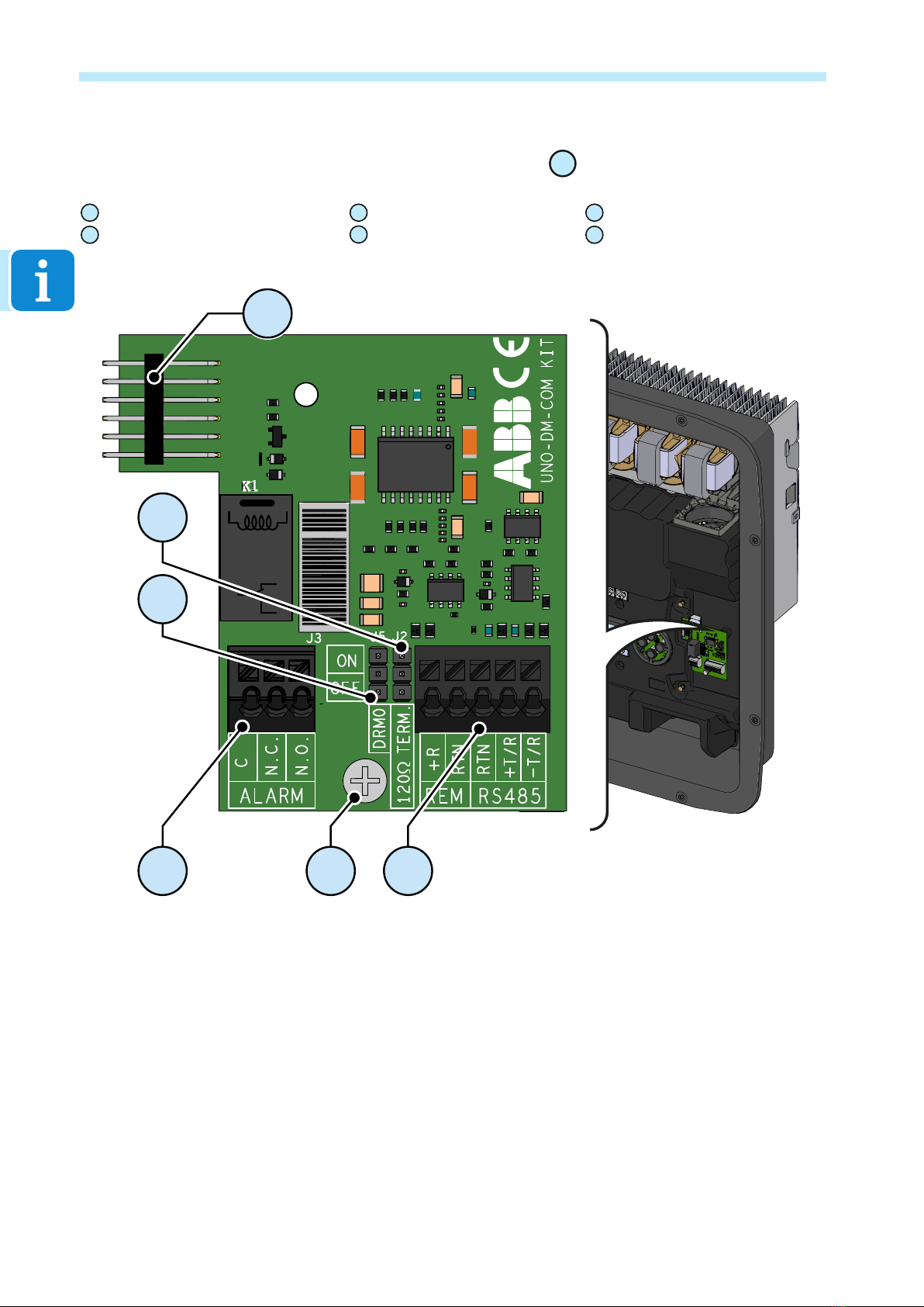
Communication and control signal connections to the UNO-DM-COM KIT board (only for -X / -E version)
....78
Description of terminal blocks on the UNO-DM-COM KIT board (only for -X version)
......................79
Description of terminal blocks on the UNO-DM-PLUS-COM Ethernet KIT board (only for -E version)..
80
Connection of the RS485 line...........................................................................................81
Remote control connection...............................................................................................83
Demand Responce Mode 0 (Request by AS/NZS 4777) .................................................83
Configurable Relay connection (ALARM / LOAD MANAGER)................................................84

- 7 -
000678AG
1- Introduction and general information
Connection of the energy meter .........................................................................................................85
Connection of the REACT-MTR-1PH (single-phase)...........................................................85
Connection and configuration of the ABB B23 3PH (three-phase) ......................................87
Closing the front cover ........................................................................................................................90
6. Instruments................................................................................................................................... 91
General conditions ..............................................................................................................................91
Description of keyboard and LED Panel...............................................................................92
7. Operation ...................................................................................................................................... 93
General conditions ...............................................................................................................................93
Monitoring and data transmission .....................................................................................................94
User interface........................................................................................................................94
Measurement tolerance ........................................................................................................94
Commissioning (Via internal Webserver) ..........................................................................................95
Commissioning (Using the inverter display)...................................................................................104
Power, Alarm, GFI LEDs behaviour ..................................................................................................106
Specifications on operation of the LEDs.............................................................................107
LED insulation fault .............................................................................................................107
COMM Status, RSSI LEDs behaviour...............................................................................................107
Description of the internal Webserver .............................................................................................108
Access to the internal Webserver.......................................................................................108
webserver menu structure .................................................................................................. 111
MAIN section....................................................................................................................... 112
SETUP section.................................................................................................................... 113
EVENTS Section.................................................................................................................115
USER section......................................................................................................................116
NETWORK section ............................................................................................................. 117
TOOLS section....................................................................................................................122
INFORMATION Section......................................................................................................133
Description of the Display menus ....................................................................................................134
General information ............................................................................................................134
Menu structure ....................................................................................................................135
System Menu ......................................................................................................................136
Inverter Menu......................................................................................................................138
Display Menu ......................................................................................................................152
WLAN Logger Menu ...........................................................................................................153

- 8 -
000678AG
1- Introduction and general information
8. Maintenance................................................................................................................................ 155
General conditions ............................................................................................................................155
Routine maintenance .........................................................................................................................156
Troubleshooting .................................................................................................................................157
Internal Webserver and wireless communication troubleshooting.....................................157
Alarm Messages of the Inverter..........................................................................................159
Power limitation messages .................................................................................................168
Dismantling the inverter ...................................................................................................................170
Registration on “Registration” website and calculation of second-level password (Service
menu, Admin Plus) .............................................................................................................................171
Resetting the remaining time for grid standard variation from display.......................................174
Verification of ground leakage .........................................................................................................175
Behaviour of a system without leakage ..............................................................................175
Behaviour of a system with leakage ...................................................................................176
Measuring the insulation resistance of the PV generator. ............................................................177
Storage and dismantling ..................................................................................................................178
Storage of an uninstalled inverter for long periods.............................................................178
Storage of an installed inverter for long periods of non-use...............................................178
Disposal...............................................................................................................................178
9. Attachments................................................................................................................................ 179
Port and network services used by the inverter.............................................................................179
IP Network Services............................................................................................................179
Network Hosts.....................................................................................................................180
Inverter network configuration ............................................................................................180
Further information ............................................................................................................................181
Contact us ...........................................................................................................................................182

- 9 -
000678AG
1- Introduction and general information
01 , Bracket
02 , Lock spring
03 , Heat sink
04 , Anti-condensation valve
05 , Front cover
06 , LED panel
07 , Display
08 , Keyboard
09 , DC input connectors
10 , AC output connector
11 , Wireless antenna connector
12 , DC Input terminal block
16 ,
DC disconnect switch
(Only for -S models)
18 ,
UNO-DM-COM KIT Card
(Only for -X and -E models or as op-
tional accessory)
19 , External earth connection
20 ,Service cable glands
Reference number index
Graphical representation of references
03
09 04 16 10 11 2019
01
02
03
01
18
06
07
05
08
12

- 10 -
000678AG
1- Introduction and general information
21 , Inverter connector
22 , RS485 Termination line jumper
23 , DRM0 activation jumper
24 , ALARM terminal block
25 , Fixing hole
26 , RS485 and REM terminal block
Accessory Board UNO-DM-COM KIT
(Only -X models or as optional accessory) 18
K1
J1
COM
NC NO
J4
21
25
24 26
23
22

- 11 -
000678AG
1- Introduction and general information
Accessory Board UNO-DM-PLUS-COM Ethernet KIT
(Only -E models or as optional accessory) 18
21
25
24 26 27
23
22
21 , Inverter connector
22 , RS485 Termination line jumper
23 , DRM0 activation jumper
24 , ALARM terminal block
25 , Fixing hole
26 , RS485 and REM terminal block
27 , LAN Ethernet connector

- 12 -
000678AG
1- Introduction and general information
REACT-MTR-1PH energy meter
REACT-MTR-1PH
SUTATS
ERUSAEM
INPUT :
110/230 V
50/60 Hz
10 mA max
57
56
55
54
ABB B23 3PH energy meter
59
5960
58
54 , REACT-MTR-1PH
57 , METER RS485 serial terminal block
58 , ABB B23 3PH Meter
55 , Hole for line cable
59 , terminal block for three-phase connection
56 , AC power supply terminal block
60 , METER RS485 serial terminal block

- 13 -
000004EG
1- Introduction and general information
The document and intended audience
Purpose and structure of the document
This operating and maintenance manual is a useful guide that will enable
you to work safely and carry out the operations necessary for keeping the
equipment in good working order.
If the equipment is used in a manner not specied in the installer manual, the protection
provided by the equipment may be impaired.
The language in which the document was originally written is ITALIAN; therefore, in the event
of inconsistencies or doubts please ask the manufacturer for the original document.
List of annexes
In addition to this operating and maintenance manual, (if applicable or on
request) the following enclosed documentation is supplied:
- EC declaration of conformity
- quick installation guide
CAUTION: Part of the information given in this document is taken from the original docu-
ments provided by the suppliers. This document contains only the information considered
necessary for the use and routine maintenance of the equipment.
Staff characteristics
The Customer must make sure that the operator has the necessary skills and training to do
his/her job. The staff in charge of using and maintaining the equipment must be experienced,
aware and responsible enough to perform the tasks described and must reliably demonstrate
their ability to interpret what is described in the manual correctly.
For safety reasons, only a qualied electrician who has received training and/or demon-
strated skills and knowledge on the structure and operation of the unit may install the inverter.
The installation must be performed by qualied installers and/or licensed electricians in ac-
cordance with the existing regulations in the country of installation.
The employment of a person who is NOT qualied, is drunk, or on narcotics, has a prosthetic
mitral valve or a pacemaker is strictly forbidden.
The customer has civil liability for the qualication and mental or physical state of the pro-
fessional gures who interact with the equipment. They must always use the personal pro-
tective equipment provided for by the laws of the country of destination and whatever else is
provided by their employer.

- 14 -
000006GG
1- Introduction and general information
Symbols and signs
In the manual and/or in some cases on the equipment, the danger or
hazard zones are indicated with signs, labels, symbols or icons.
Symbol Description
Indicates that it is mandatory to consult the manual or original document,
which must be available for future use and must not be damaged in any
way.
General warning - Important safety information. Indicates operations or
situations in which staff must be very careful.
Dangerous Voltage - Indicates operations or situations in which staff
must be very careful with regard to dangerous voltage levels.
Hot parts - Indicates a risk arising from the presence of hot zones or
zones with parts at high temperatures (risk of burns).
Risk of explosion
Risk of injury due to the weight of the equipment. Take care during lifting
and transport
Indicates that the area in question must not be accessed or that the
operation described must not be carried out.
Keep out of the reach of children
Indicates that smoking and the use of naked ames is prohibited.
Indicates that it is mandatory to carry out the described operations
using the clothing and/or personal protective equipment provided by the
employer.
WEEE logo. Indicates that the product is to be disposed of according to
current legislation regarding the disposal of electronic components.
IPXX Indicates the protection rating of the equipment according to IEC 70-1
(EN 60529 June 1997) standard.
Point of connection for grounding protection.
Indicates the permitted temperature range

- 15 -
000006GG
1- Introduction and general information
Symbol Description
5
Indicates a risk of electric shock. Stored energy discharge time: 5 minutes
10
Indicates a risk of electric shock. Stored energy discharge time: 10
minutes
DC
Direct Current
AC
Alternating current
With insulation transformer
Without insulation transformer
Positive pole of the input voltage (DC)
Negative pole of the input voltage (DC)
Indicates the centre of gravity of the equipment.
Indicates the requirement to wear acoustic protection devices in order to
prevent damage to hearing

- 16 -
000007CG
1- Introduction and general information
Field of use, general conditions
ABB accepts no liability for damage of any kind that may arise from incor-
rect or careless operations.
You may not use the equipment for a use that does not conform to that provided for in the
eld of use. The equipment MUST NOT be used by inexperienced staff, or even experienced
staff if carrying out operations on the equipment that fail to comply with the indications in this
manual and enclosed documentation.
Intended or allowed use
This equipment is a string inverter designed to:
transform a direct current (DC)
supplied by a photovoltaic generator (PV)
in an alternating electrical current (AC)
suitable for feeding into the public distribution network.
Limits in field of use
The inverter can be used only with photovoltaic modules which have ground isolated input
poles, unless they are accessories installed that enable grounding of the inputs. In this case
you must install an insulating transformer on the AC side of the system.
Only a photovoltaic generator can be connected in the input of the inverter (do not connect
batteries or other sources of power supply).
The inverter can be connected to the electricity grid only in countries for which it has been
certied/approved.
The inverter cannot be connected to the DC side in parallel to other inverters to convert en-
ergy from a photovoltaic generator with a power greater than the nominal power of the single
inverter.
The inverter may only be used in compliance with all its technical characteristics.
Improper or prohibited use
IT IS STRICTLY FORBIDDEN TO:
• Install the equipment in environments with particular ammability conditions or in adverse or
disallowed environmental conditions (temperature and humidity).
• Use the equipment with safety devices which are faulty or disabled.
• Use the equipment or parts of the equipment by linking it to other machines or equipment,
unless expressly provided for.
• Modify operating parameters that are not accessible to the operator and/or parts of the
equipment to vary its performance or change its insulation.
• Clean the equipment with corrosive products that may corrode parts or generate electro-
static charges.
• Use or install the appliance or parts of it without having read and understood the contents of
the user and maintenance manual.
• Warm or dry rags and clothes on parts at temperature. In addition to being hazardous, doing
so would compromise component ventilation and cooling.

- 17 -
000008EG
General conditions
The characteristics of the equipment are described so that its main
components can be identied and the technical terminology used in the
manual can be explained.
Technical terminology and the fast information retrieval system, are
supported by:
• Table of contents
• Reference number index
The Characteristics chapter contains information about the models,
details of the equipment, characteristics and technical data, overall
dimensions and identication of the equipment itself.
The customer/Installer takes full responsibility if, when reading this manual, the chronological
order of its presentation established by the manufacturer is not observed. All information is
provided and occasional reference may be made to information in previous chapters.
In certain cases, there may be a need to separately document software
functionality or attach supplementary documentation to this manual
intended for more qualied professional gures.
2
Characteristics

- 18 -
000679AG
2 - Characteristics
Models and range of equipment
The models of single-phase inverters covered by this manual are divided
into six groups according to their maximum output power:
1.2kW, 2.0kW, 3.3 kW, 4.0 kW, 4.6 kW and 5.0 kW.
For each model, the following variants are available (sufx could be com-
bined):
- Models with “B” sufx (e.g. UNO-DM-3.3-TL-PLUS-B).
Models equipped with Wireless communication.
- Models with “S” sufx (e.g. UNO-DM-3.3-TL-PLUS-S).
Models equipped with DC disconnecting switch 16 .
- Models with “E” sufx (e.g. UNO-DM-3.3-TL-PLUS-E).
Models equipped with Wireless communication and Accessory Board
equipped with Ethernet board (UNO-DM-PLUS-COM Ethernet KIT)
18
.
- Models with “X” sufx (e.g. UNO-DM-3.3-TL-PLUS-X).
Models equipped with Accessory Board (UNO-DM-COM KIT) 18 .
The choice of the inverter model must be made by a qualied technician who knows about
the installation conditions, the devices that will be installed outside the inverter and possible
integration with an existing system.

- 19 -
000679AG
2 - Characteristics
Identification of the equipment and manufacturer
The technical data provided in this manual does not substitute the data
supplied on the labels afxed to the equipment.
The labels afxed to the equipment must NOT be removed, damaged, stained, hidden, etc.,
for any reason whatsoever.
The Regulatory label contains the following information:
1. Manufacturer
2. Model
3. Rating data
4. Certication marks
The labels are NOT to be hidden by foreign objects and parts (rags, boxes, equipment, etc.);
they must be regularly cleaned and always kept in sight.
1
4
2
3
1
4
2
3
1
4
2
3
1
4
2
3
1
4
2
3
1
4
2
3

- 20 -
000679AG
2 - Characteristics
Besides the Regulatory label, an additional product label is also provided.
The label displays the following information:
An additional Wireless Identication label is provided.
The label displays the following information:
The Wireless Identication label is divided in two separate parts by a dashed line; take the
bottom part and apply it on the cover page of the quick installation guide.
The ofcially required information is located on the Regulatory label. The product label or the
Wireless Identication label are accessory labels which shows the information necessary for
the identication and characterisation of the inverter by ABB.
Note: The labels are NOT to be hidden by foreign objects and parts (rags, boxes, equipment,
etc.); they must be regularly cleaned and always kept in sight.
• Inverter model
- X.X = Inverter power rating:
- X = Integrated disconnect switch (-S)
- Y = Integrated WLAN board (-B) or WLAN
board and Accessory Board equipped
with Ethernet board (-E)
- J = Integrated Accessory Board (-X)
• Inverter Part Number
• Inverter Serial Number consisting of:
- YY = Year of manufacture
- WW = Week of manufacture
- SSSSSS = sequential number
• Week/Year of manufacture
P/N:PPPPPPPPPPP
WO:XXXXXXX
SO:SXXXXXXXX Q1
SN:YYWWSSSSSS WK:WWYY
UNO-DM-X.X-TL-PLUS-XY-J
ABB
• WLAN board Serial Number
• WLAN Board Part Number
• Inverter Serial Number
• WLAN Board MAC address:
- To be used to obtain the SSID of the wireless access point
created by the inverter: ABB-XX-XX-XX-XX-XX-XX
(where “X” is a hex digit of the MAC address).
- To be used to obtain the “Host Name”:
http://ABB-XX-XX-XX-XX-XX-XX.local
(where “X” is a hex digit of the MAC address).
- MAC address it’s the only required information to register the
inverter with Aurora Vision.
• Product Key:
To be used as wireless access point password, after 24 hours
which the inverter is power on (then the default password
“ABBSOLAR” is expired) or to be used to access to the internal
webserver as username and password in case of lost credentials.
This manual suits for next models
5
Table of contents
Other ABB Inverter manuals

ABB
ABB TRIO-20.0-TL-OUTD User manual

ABB
ABB ACS880-104 User manual

ABB
ABB PVS800-IS User manual

ABB
ABB TRIO-50.0-TL-OUTD-US User manual

ABB
ABB PVS-166-TL-US User manual

ABB
ABB ACS880-104 User manual

ABB
ABB PVS980-58 Use and care manual

ABB
ABB PVI-GSM/GPRS User manual

ABB
ABB REACT 2 Series User manual

ABB
ABB TRIO-50.0-TL-OUTD-US User manual

ABB
ABB TRIO-TM-60.0-US-480 User manual

ABB
ABB ACS350 Series User manual

ABB
ABB UNO-DM-1.2-TL-PLUS User manual

ABB
ABB ESI-S Manual

ABB
ABB TRIO-20.0/27.6-TL-OUTD User manual

ABB
ABB PVS980-MWS User manual

ABB
ABB PVI-3.0-TL-OUTD-W User manual

ABB
ABB PVI-3.0-TL-OUTD-S-US User manual

ABB
ABB PVS-100 Series User manual

ABB
ABB PVI-3.0-TL-OUTD User manual