13.
Grid support functions
11.
AFD (arc fault detection)
10.
Commissioning
9.
User Interface
12.
Response to abnormal conditions
UNO-DM-6.0-TL-PLUS-US-Quick Installation Guide EN-RevB
EFFECTIVE 2018-02-15
© Copyright 2018 ABB. All Rights Reserved.
Specications and illustrations subject to change without notice.
8.
AC Output connection
Technical Data
14.
Contact us
www.abb.com/solarinverters
The inverter is equipped with advanced grid support functionality that is useful to support reactive loads and also assist in reliable operation of the utility grid in
the presence of a large number of distributed energy generation sources. This section provides an overview of the available grid support functions.
The parameters related to the grid support functions that are in this inverter can be modied by:
- Accessing the embedded Web User Interface.
- Accessing to settings under the Service menu requires a time-limited password, which can be obtained by calling ABB solar inverter technical support at 1-877-261-1374.
1. Voltage ride-through
This inverter provides parameters to respond to undervoltage and overvoltage events. The inverter is designed to operate normally within the specied operating range.
If voltage excursions occur, the inverter is designed to continue operating normally or cease to export power for a specied delay. Beyond this programmed delay, the
inverter disconnects from the grid in the event of an abnormal voltage condition.
2. Frequency ride-through
This inverter provides parameters to respond to underfrequency and overfrequency events. If frequency excursions occur, the inverter is designed to continue opera-
ting normally for a specied delay. Beyond this programmed delay, the inverter disconnects from the grid in the event of an abnormal voltage condition.
3. Reactive power control
The inverter provides several modes of operation for reactive power control and are described below:
- Disable: This is the default setting. Under this setting, the inverter exports with a power factor of 1.0.
- Fixed power factor control (Cosɸ set): In this mode, the operator can set the output power factor to a xed value. When enabled, a new value will be set in the
inverter.
- Q Fixed (Q Set): Sets the reactive power to a xed value. When enabled, a new value will be set in the inverter.
- Power factor as function of output power (Watt/Cosφ Settings: Cosφ(P)): In this mode, the inverter reduces the power factor (cos-phi) as a function of the output
power at a given operating point. The 4 points of the default curve, where you can set the % of Pmax values and related cos-phi, can be modied using the internal
Webserver. When enabled, the curve will be set in the inverter.
- Dynamic Volt/VAR control (Volt/VAr Settings: Q(V)): Under this mode, the level of reactive power exported by the inverter is a function of the operating grid voltage,
also known as a Volt/VAR curve. The 4 points of the default curve, where you can set the % of Vnom values and related % of Smax, can be modied using the
internal Webserver. When enabled, the curve will be set in the inverter.
4. Active Power Control
This inverter offers several modes for active power reduction.
- Active Power Curtailment: Sets a new value of active power as % of Pmax. When enabled, a new value will be set in the inverter.
- CEI Average VGrid Derating (only italian grid standard): Sets, after a specic threshold, an active power derating based on the average of Vac on 10 minutes as per
CEI-021 italian grid standard.
- Volt/Watt settings: P(V). Under this mode, the level of active power exported by the inverter is a function of the operating grid voltage, also known as a Volt/Watt cur-
ve. The 4 points of the default curve, where you can set the % of Vnom values and related % of Pmax, can be modied using the internal Webserver. When enabled,
the curve will be set in the inverter.
- Frequency/Watt function (Frequency Control: P(f)): In this mode, the inverter limits the active power as a function of the grid frequency.
5. Ramp control
The inverter is designed to control the rate at which output power is increased, either at startup, or after a temporary low power condition on the PV array (such as fast
shading). The following ramp controls are provided on this inverter.
- Normal ramp: The normal ramp denes the maximum rate at which the inverter can increase the output power under normal operation. The normal ramp control
limits the uctuations in the output power in order to prevent instabilities on the utility grid.
- Soft start: The soft-start ramp denes the maximum rate at which the inverter can increase the output power when the inverter is rst starting up. This startup may
occur on a daily basis or when the inverter restarts after an abnormal grid event has ended.
Refer to the dedicaterd application note in the ABB Solar website for more details about the grid support functions.
The DC AFD fault circuit interrupter automatically runs a self test every morning when sunlight is sufcient for connection. The inverter display area shows the
results of the selftest:
- If the self-test results are OK, the inverter will continue with the AC grid connection.
- If a potential problem on the Arc Fault Detection (AFD) board is detected, the self-test will result in an error.
Press the ESC key to clear the error and start the restart selftest. If self-test results are OK, the inverter will reconnect to the AC grid.
If the DC arc fault is still present, the self test will result in error code E050.
Refer to the product manual which must be downloaded at www.abb.com/solarinverters for troubleshooting suggestions.
- During normal operation, the input current is continually measured and analyzed.
- If a DC arc fault is detected, the inverter is disconnected from the AC grid and error E050 will be displayed.
The AFD self-test can be manually started anytime using the following procedure:
1. Turn off the inverter (switching off both DC and AC switches) and,
2. Turn on both the DC and AC switches and wait for the self-test results on the display.
Test Arc Sensor
OK
Test Arc Sensor
E053
Test Arc Sensor
E050
To prevent electrocution hazards, open and lock out the external AC disconnect switch before connecting the AC conductors, and any
time the AC wiring box cover is to be removed. Proper PPE is required.
AC output overcurrent protection is not provided with the inverter; it is the responsibility of the end user to provide overcurrent protec-
tion for the AC output circuit. To reduce the risk of re, connect only to a circuit provided with an overcurrent protection in accordance
with the NEC (ANSI/NFPA 70). The inverter must be connected only to a dedicated branch circuit provided with the maximum branch
overcurrent protection device (OCPD) listed in the technical data sheet at the end of this document.
Size conductors per the NEC, Article 310 - use 90°C copper wire only; conductors must be sized according to operating temperature
range and continuous current ratings. The AC grid wiring is connected through the inverter switchbox.
AC output wire must be listed PV wire rated minimum 600V.
- Run an approved raceway between the inverter and external AC disconnect switch.
- Pass the AC wires throught the openings dedicated to the AC conduit.
When complete, seal conduit with water-tight ttings to maintain the NEMA type 4X enclosure rating.
Installer should follow conduit manufacturers’ guidelines and best practices.
- Determine which AC output is applicable for the inverter model being installed. The AC
wiring connections based on the AC grid type are shown in the table (also found on a label
in the wiring box).
208V~
3PH -
240V~
SPLIT-PHASE
GRID STANDARD
TYPE DE RÉSEAU
TERMINAL
BORNE
WIRE
CÂBLE
L2
L1
N
L1
L3 L2
1
L1
2
L2
3
-
CAUTION
Thisisasingle phase inverter. Use thewiringschemes shown on the
table below when adifferent grid standardis used. Refer to the
instruction manual to properly set theinvertergrid standard fromthe
front panel display. Use 90°C copper wire only. Refer to theinstruction
manual forwiringinstructions.
ATTENTION
Ceci est un onduleur monophasé.Utilisez lesschémas de raccordement
ci-dessussileréseau est spécifique.Réferez-vousaumanuel
d'installation pour sélectionner via l'afficheur frontal le code pays
adéquat.Utilisez seulement câbles en cuivre90°C.
Consulterle manual d'installation pour lesinstructions de câblage.
AWG# 4 - 8
1
L1
2
L2
3
N
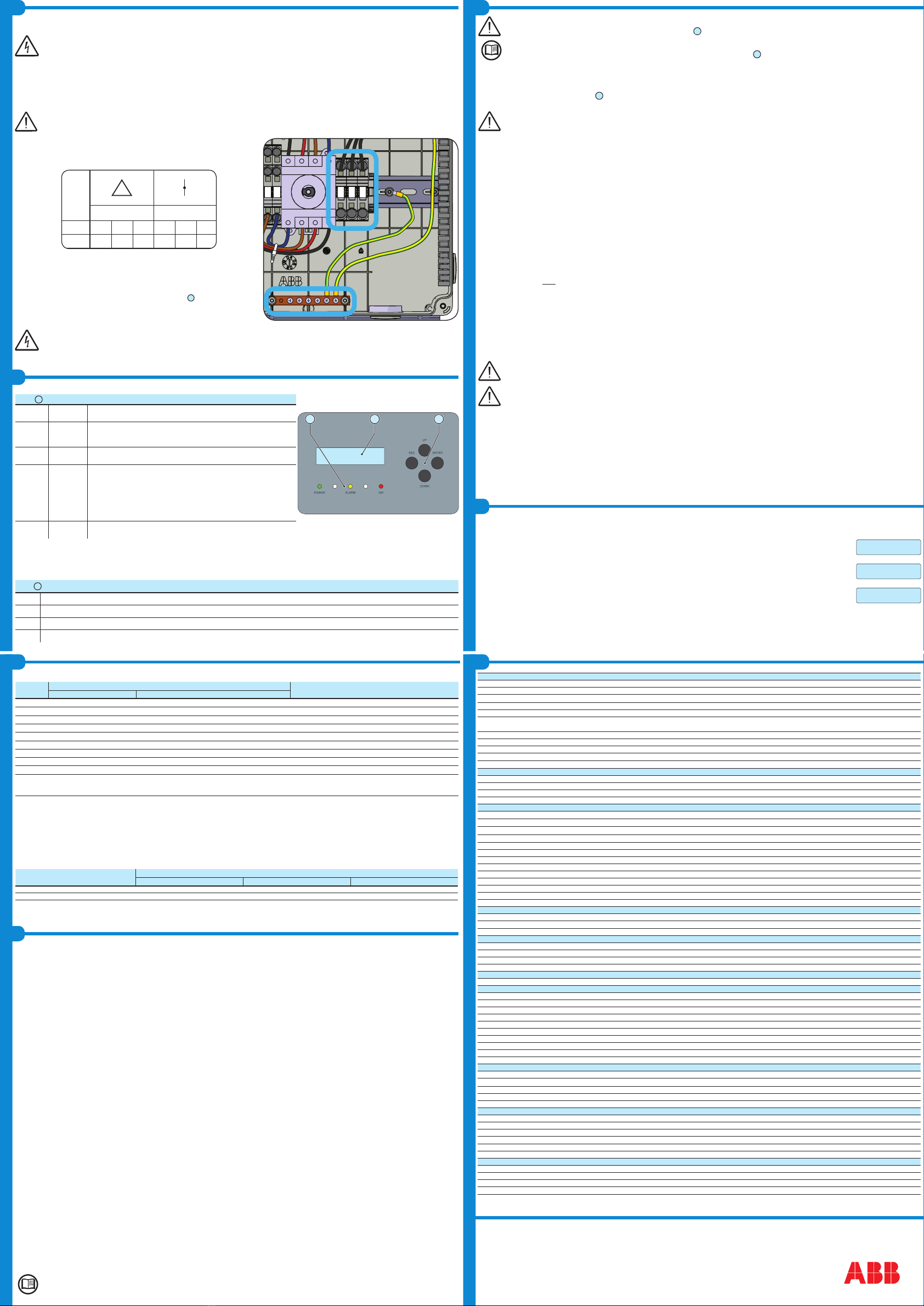
- Connect wiring to the numbered terminals based on selected grid type. AC wiring terminals are
spring pressure type and accommodate a wire size range of 20-6 AWG.
- Connect the protective earth (PE) cable to wiring box busbar
16
. Screws the cable (max
4 wires 8AWG to 4AWG, copper) with 2.0Nm (1.5ft-lb) torque.
The default 240V split-phase connection requires the grid Neutral to be connected to the inverter for proper operation. Before connecting
the inverter to the grid, the grid type must be selected during the commissioning phase. If several inverters are installed to a three-phase
AC grid, always distribute the inverters between the phases in order to reduce power imbalance between the phases.
- When all connections are complete, reinstall the front covers and tighten the cover screws with 1.5Nm (13.2 in-lbs) torque.
CAUTION
ATTENTION
REFER TO LOCAL CODE
FOR WIRE SIZE
FAIRE RÉFERENCE À LA
LÉGISLATION LOCALE POUR
LA DIMENSION DU CABLE
-IN1
+IN1
-IN2
+IN2
1
2
3
-RSD
+RSD
Abnormal grid conditions: The inverter is programmed to respond to abnormal grid conditions, as specied in the below table:
Condition Utility source Max. time (sec) at 60Hz before cessation of current
Voltage (V) Frequency (Hz)
A <0.50 Vnom1 (Fixed) Rated (60Hz) Default setting3 0.16 (Adj. 0.16 to 50)
B0.50 Vnom1 ≤ V < 0.88 Vnom1Rated (60Hz) Default setting3 2 (Adj. Set Points 0.16 to 100 sec)
C1.10 Vnom1 < V < 1.2 Vnom1Rated (60Hz) Default setting3 1 (Adj. Set Points 0.16 to 100 sec)
D1.20 Vnom1 ≤ V Rated (60Hz) Default setting3 0.16 (Adj. 0.001 to 0.16 sec)
E Rated Default setting3 f > 60.5 Hz (Adj. 60.1 to 66.0 Hz) Default setting3 0.16 (Adj. Set Points 0.16 to 1000 sec)
F Rated Default setting3 f < 59.3 Hz (Adj. 50.0 to 59.9 Hz) Default setting3 0.16 (Adj. Set Points 0.16 to 1000 sec)
G Rated Default setting3 f << 57.0 Hz (Adj. 50.0 to 59.9 Hz) Default setting3 0.16 (Adj. Set Points 0.16 to 1000 sec)
H Rated Default setting3 f >> 63.0 Hz (Adj. 60.1 to 66.0 Hz) Default setting3 0.16 (Adj. Set Points 0.16 to 1000 sec)
Reconnection 300s (Default setting3). Adjustable 20s to 1000s.
1. Vnom is the nominal output voltage rating.
2. Trip limit and trip time accuracy specication is as follows: Voltage: +/-2%, Frequency: +/- 0.10Hz, Time: 2 grid cycles (33ms @ 60Hz).
3. Default settings aligned with IEEE 1547-2003 requirements.
To adjust voltage and frequency and disconnect times to meet local utility requirements, make modications are made using :
- The inverter embedded web user interface. The Token is required to unlock the “Admin Plus” functionalities (contact ABB solar inverter technical support
1-877-261-1374).
- The LCD display. A time-limited service password is required, contact ABB solar inverter technical support 1-877-261-1374.
- Aurora Manager LITE software. Connect the inverter equipped with UNO-DM-COM kit UNO or UNO-DM-PLUS-Ethernet COM kit to a PC through a RS-485/USB
adapter. Download the manual at www.abb.com/solarinverters. An User ID and a password is required to unlock the “installer” functionalities of the software,
contact ABB solar inverter technical support 1-877-261-1374.
Fault currents and durations: During a grid fault including a short circuit condition, the inverter may inject current into the grid as specied below:
Utility voltage (V) Fault current RMS (A)
1 cycle 3 cycle 5 cycle
208 17.4 15.9 15.8
240 17.1 16.5 16
Output power derating at high ambient temperature: Under high ambient temperatures, the inverter is designed to automatically reduce its output power.
Detailed derating curves by model are provided in the product manual found on www.abb.com/solarinverters.
LED and KEYS, in various combinations, may display the status conditions or perform complex actions to be explored by consulting the product manual.
LEDs
06
POWER
Green Solid when the inverter is working correctly. Flashes when checking the grid or
if there is insufcient sunlight.
COMM
STATUS Multicolor
Operation status of wireless communication line:
- Blink Red: Communication error (no communication available)
- Green: Communication OK
ALARM Yellow The inverter has detected an anomaly. The anomaly is shown on the
“EVENTS” section of the internal webserver and on the display.
RSSI Multicolor
Communication type and quality of the wireless communication signal (for “Station
Mode”):
- Blink Blue: Wireless board is working in Access Point mode (AP Mode)
- OFF: No signal
- Blink Red: Low signal strenght
- Blink Yellow: Medium signal strenght
- Blink Green: High signal strenght
GFI Red Ground fault on the DC side of the PV generator. The error is shown on
the “EVENTS” section of the internal webserver and on the display.
The LCD has two visible text lines and the UP and DOWN control keys are used to scroll through the menu items. An arrow on the left side of the display highlights
the current selection. Move the arrow UP or DOWN to the desired selection and press ENTER to access the associated submenu. To return to the preceding menu,
press the ESC key.
- Press ESC to open the menus. Use the DOWN key to scroll the submenus.
- The default password for Setting menus is 0000.
Keys
08
ESC Used to access the main menu, to go back to the previous menu or to go back to the previous digit to be edited.
UP Used to scroll upwards the menu options or to shift the numerical scale in ascending order.
DOWN Used to scroll downwards through the menu options or to shift the numerical scale in descending order.
ENTER Used to conrm an action, to access the main menu or the submenu for the selected option (indicated by the > symbol) or to switch to the next digit to edit.
COMM
STATUS
RSSI
080706
Before proceeding with commissioning, make sure you have carried out all the operations and checks indicated in the previous sections of
this quick installation guides, and verify that the inverter cover
05
was properly closed!
Refer to the product manual for further information about the conguration and the use of the functionality of the internal Webserver.
Commissioning and conguration of the inverter can also be done with the display
07
. Consult the product manual for more information.
Commissioning and conguration of the inverter can be made using a wireless capable device such as a smartphone, tablet or laptop.
The steps for commissioning are listed below:
1. Set the inverter’s DC disconnect switch
16
and any external DC switches to “ON” position: If the input voltage applied to one of the two input channels is
greater than the minimum starting voltage, the inverter will start up.
The inverter is powered ONLY by the voltage coming from the photovoltaic generator: the presence of grid voltage alone IS NOT SUFFI-
CIENT to allow the inverter to power up.
If a RSD device was istalled into the plant, it also will needed to connect the AC grid to allow the inverter to power-up!
2. Set the external AC disconnect switch downstream to the inverter to “ON” position.
3. Enable Wireless on the device that is being used for the inverter commissioning (tablet, smartphone or PC) and connect it to the Access Point created by the
inverter: a network with the name ABB-XX-XX-XX-XX-XX-XX will appear in the list of networks, where “X” is a hex digit of the MAC address (MAC address
can be found on the “Wireless Identication Label” placed on the side of the inverter or previously applied to this quick installation guide - see cover page).
4. When prompted, type the “product key” (including the dashes. Example: 1234-1234-1234-1234) as the network password to access the inverter’s access
point. The product key is printed on the “wireless identication label”on the side of the inverter.
5. Open the internet browser (recommended browser: Chrome versions from v.55, Firefox versions from v.50, Safari versions from v.10.2.1) and enter the pre-
set IP address to access the conguration wizard page: 192.168.117.1
6. A conguration wizard will open, consisting of a sequence of steps in which all the required elds must be completed correctly (language of the wizard can be
selected in the upper status bar). The steps and information required by the conguration wizard are:
STEP 1 - Set the Administrator/User login credentials (minimum 8 character for password). User and password are CASE SENSITIVE.
STEP 2 (OPTIONAL) - Enter the required information (IP selection mode, SSID and Password) to connect the inverter to the residential wireless network
with “Station Mode” (Note: This step can be skipped to continue operating with the point-to-point connection “AP mode”). Once the inverter is connected to
the wireless network it will be necessary switch the tablet/smartphone/PC device to the same wireless network to which the inverter is connected to proceed
with the conguration wizard (for any difculties concerning this step, refer to the “Internal Webserver and wireless troubleshooting” chapter of the product
manual). Once the connection is acquired, a new message will provide you the links (corresponding to the IP Address assigned by the router to the inverter
and the “Host Name”) that can be used each time you want to access the internal webserver. TAKE NOTE OF THEM.
STEP 3 - Set the Date, Time and Time zone (The inverter will propose these elds when available).
STEP 4 - Set the inverter country standard, Input channel conguration and Meter conguration (if installed). Clicking the “END” button the wizard will be
completed (after conrmation the inverter will reboot).
From the moment that the grid standard is set, you have 24 hours to make any changes to the value, after which the “Country Select” func-
tionality is blocked and the remaining time will have to be reset in order to have the 24 hours of operation available again. To select a new
grid standard follow the procedure “Resetting the remaining time for grid standard variation” described in the product manual.
Any inverters installed, or commissioned, in California after September 8, 2017 must be set to the Rule 21 country code
USA - RULE21 @ 240 single [R21 240sp] or USA - RULE21 @ 208 single [R21 208si].
Once both AC and DC switches are closed and the wizard commissiong procedure is nished, the inverter starts the grid connection sequence: the inverter
performs the grid voltage check, measures the PV array insulation resistance against earth and carries out other self-diagnosis checks.
During the checks before the connection with the grid, the “Power” LED keeps ashing, the “Alarm” and “GFI” LEDs are off. If there is not sufcient sunlight to
connect to the grid, the inverter will repeat the connection procedure until all the parameters are within range.
If the preliminary checks for parallel connection to the grid are successful, the inverter connects to the grid and begins to export power to the grid.
The “Power” LED remains xed on while the “Alarm” and “GFI” LEDs are off.
UNO-DM-6.0-TL-PLUS-US
Input
Absolute maximum input voltage (Vmax,abs) 600 V
Start-up voltage (Vstart)default 200 V (120...350 V)
Operating MPPT voltage range (Vdcmin...Vdcmax)0.7xVstart...580 V (≥ 90V)
Maximum usable power (PdcrMPPT) - each channel 4000 W
Number of Independent MPPT 2
Full power MPPT voltage range (VMPPT min ... VMPPT max)
with parallel MPPT conguration a Pacr
160...480 V
Maximum usable current (Idc max) - each channel 20.0 A
Maximum current (Idc max)40.0 A
Maximum short circuit current (Isc max) - each channel 24 A
Number of wire landing terminals 2 pairs, capable of connecting two parallel strings
Array wiring termination Terminal block, pressure clamp, AWG20-8
Input protection
Reverse Polarity Protection Yes, from current limited source
Over-voltage protection type Varistor
PV array ground fault detection Pre start-up RISO and dynamic GFDI
DC switch rating (per contact) 600 V / 32A
Output
AC grid connection type 1Φ/2W or Split-Φ/3W
Nameplate Apparent Power (Smax) 6200 VA (208 Vac); 6650 VA (240 Vac)
Nameplate Output Active Power (Pacr@cosφ=1)6000 W (208 Vac); 6000 W (240 Vac)
Output Active Power @Vacr and cosφ=±0,9 (PRated)5600 W (208 Vac); 6000 W (240 Vac)
Nominal AC output voltage (Vacr)208Vac (1Φ/2W) or 240Vac (Split-Φ/3W)
Output AC voltage range (Vacmin...Vacmax)183...228Vac (1Φ/2W) or 211...264Vac (Split-Φ/3W)
Maximum current (Iac max)30 A
Contributory fault current 40 Arms; 100ms
Nominal output frequency (fr) 60 Hz
Adjustable grid frequency range (fmin...fmax)50...64 Hz
Power factor and adjustability range >0.995, adj. +/-0.9
Total harmonic distortion at rated power <2%
Grid wiring termination type Terminal block, pressure clamp, AWG20-6
Output Protection
Anti-islanding protection Meets UL1741 / IEEE1547 requirements
Over-voltage protection type Varistor, 2 (L1 - L2 / L1 - G)
Maximum AC OCPD rating 40.0 A
Operating Performance
Maximum efciency (η
max
)97.4%
CEC efciency 96.5% (208 Vac); 97% (240 Vac)
Stand-by consumption < 8.0 Wrms
Night-time consumption < 0.6 Wrms
Auxiliary Output
Isolated Auxiliary Power Supply (1) 24Vdc, 0.4A max
Communication
Embedded Communication interface Wireless (2)
Embedded Communication Protocol ModBus TCP (SunSpec)
Commissioning Tool Web User interface, Display, ABB Manger Lite
Monitoring Plant Portfolio Manager, Plant Viewer, Plant Viewer for Mobile (4)
Optional board UNO-DM-COM Kit
Optional Communication Interface RS485 (use with meter for dynamic feed-in control), Alarm/Load manager relay, Remote ON/OFF
Optional Communication Protocol ModBus RTU (SunSpec), Aurora Protocol
Optional board UNO-DM-PLUS-Ethernet COM Kit
Optional Communication Interface Ethernet, RS485 (use with meter for dynamic feed-in control), Alarm/Load manager relay, Remote ON/OFF
Optional Communication Protocol ModBus TCP (SunSpec), ModBus RTU (SunSpec), Aurora Protocol
Environmental
Ambient air operating temperature range
-13°F to +140°F (-25°C to +60°C) with automatic power reduction above 113°F (45°C)
Relative Humidity 5-100% RH condensing
Acoustic noise emission level < 50 db (A) @1m
Maximum operating altitude without derating 6560ft (2000m)
Environmental class Outdoor
Mechanical specications
Enclosure rating Certied to NEMA Type 4X
Cooling system Natural convection
Dimensions (H x W x D) 34.0 x 16.4 x 6.9in (728 x 553 x 180mm) (3)
Weight 47.4lb (21.5kg) (3)
Mounting system Wall bracket
Conduit connections (2) Bottom: Markings for (2) concentric KOs 1”, 3/4” and (2) KOs 1/2” - Sides: Markings for concentric KOs 1”, 3/4”
Safety
Insulation level Transformerless (oating array)
Safety and EMC standard
UL1741, IEEE1547.1, CSA-C22.2 N. 107.1-01, UL1998 UL 1699B, FCC Part 15 Class B
Grid standard UL 1741 SA, IEEE 1547, Rule 21, Rule 14 (HI)
Safety approval cTUVus
1. The auxiliary output is used to supply the RSD contactors when required. 2. WLAN IEEE 802.11 b/g/n @2,4GHz
3. When equipped with DC switch and wiring box 4. Plant Viewer per Mobile availble remotely only, not for local commissioning.
Note. Features not specically mentioned in this data sheet are not included in the product


