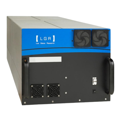
ABB GLA133 Series User manual

—
ABB MEASUREMENT & ANALYTICS | USER MANUAL
GLA133 Series
UAV-Microportable analyzers

2UAV-MICROPORTABLE ANALYZERS | GLA133 SERIES | UM/GLA133-EN REV.B
Contents
Disclaimer ........................................ 4
Cybersecurity Disclaimer .......................... 4
Patent ............................................ 4
Copyright......................................... 4
Customer Support ................................ 4
1 Introduction ................................5
2 Standard Scope of Supply ....................5
3 Recommended Tools .........................6
4 Safety ......................................6
Intended Use...................................... 6
Sound ............................................ 6
Class of Laser Equipment .......................... 6
Certification .......................................7
WEEE Directive.....................................7
Labels .............................................7
Operator Safety ................................... 8
Electrical Hazards ................................. 8
Laser Hazards..................................... 8
Internal Laser-Interlock Switch ..................... 9
Transportation and Storage of Boxed Analyzers ..... 9
Text Formats and Warning Icons ................... 9
Text Formats...................................... 9
Warning Icons ..................................... 9
5 Product Specification ...................... 10
Environmental Requirements ......................11
Performance Specifications........................11
6 Features and Measurement Theory...........12
Connection Ports .................................12
Gas Inlet ..........................................12
Power ............................................12
Data Interface.....................................12
Plumbing Diagram ................................12
7User Interface Operation ....................13
Malware Protection................................13
Set Up Communication ............................13
WiFi Setup ........................................13
VNC Server First-Time Activation ...................15
VNC Viewer User Interface .........................15
Log In. . . . . . . . . . . . . . . . . . . . . . . . . . . . . . . . . . . . . . . . . . . . .16
Security Button ...................................17
Change User Password ............................17
Add New User .....................................18
Log Out...........................................18
Control Bar .......................................18
Display ...........................................19
Numeric Display...................................19
Spectrum Display .................................19
Timechart Display ................................ 20
Alarm Status Display.............................. 20
Rate Button .......................................21
File Transfer Menu................................ 22
Standard Data File................................ 22
Transfer Data Files ............................... 22
Directory Types in Local Hard Drive................ 23
Daily Directory ................................... 23
Archive Directory ................................. 23
File Transfer Error Screen ......................... 24
Setup Button..................................... 24
Time/Files ....................................... 24
Calibration....................................... 25
Laser Adjust ..................................... 26
Service .......................................... 26
Serial Logger......................................27
Active Listeners (OPT-DATALOG Option) ............27
Serial Port Settings................................27
Parsed Debug .....................................27
Save or Restore Configuration .....................27
Security ......................................... 28
User Management................................ 28
Set OA-ICOS Default Data......................... 32
Analyzer Shutdown ............................... 32

UAV-MICROPORTABLE ANALYZERS | GLA133 SERIES | UM/GLA133-EN REV.B 3
8Service ....................................33
Cleaning the Analyzer ............................ 33
Cleaning the Instrument Exterior Casing........... 33
Preventive Maintenance .......................... 33
Daily Operation Checklist ......................... 33
Recommended Maintenance ...................... 33
Mirror Ringdown Time and Maintenance ........... 34
Other Components ............................... 34
Fuse Replacement ................................ 34
Analyzer Cover Maintenance ...................... 35
Appendix A Spare Parts and Kits ........... 36
Mirror Cleaning Kit ............................... 36
Spare Parts Kit – Pump and Filters................. 36
Spare Filters ..................................... 36
Spare Analyzer Shroud............................ 36
Spare Router ..................................... 36
Appendix B Packaging and Shipping the
Analyzer .................................. 36
Contents

4UAV-MICROPORTABLE ANALYZERS | GLA133 SERIES | UM/GLA133-EN REV.B
Disclaimer
This document contains product specifications and
performance statements that may be in conflict with other ABB
published literature, such as product flyers and product
catalogs. All specifications, product characteristics, and
performance statements included in this document are
suggested specifications only. In case of conflict between
product characteristics in this document and specifications in
the official ABB product catalogs, the latter takes precedence.
ABB reserves the right to make changes to the specifications of
all equipment and software, and to the contents of this
document, without obligation to notify any person or
organization of such changes. Every effort has been made to
ensure that the information contained in this document is
current and accurate. Please contact ABB if you find any error in
this document, so we can make appropriate corrections.
Cybersecurity Disclaimer
This product is designed to be connected to and to
communicate information and data via a network interface. It is
your sole responsibility to provide and continuously ensure a
secure connection between the product and your network or
any other network (as the case may be). You shall establish and
maintain any appropriate measures (such as, but not limited to,
the installation of firewalls, application of authentication
measures, encryption of data, etc.) to protect the product, the
network, its system and the interface against any kind of
security breaches, unauthorized access, interference, intrusion,
leakage and/or theft of data or information. ABB and its
affiliates are not liable for damages and/or losses related to
such security breaches, any unauthorized access, interference,
intrusion, leakage and/or theft of data or information.
Patent
The analyzer technology is protected by patents:
• 7,468,797
• 6,839,140
• 6,795,190
• 6,694,067
Copyright
© 2023 ABB Inc. All rights reserved. No information contained in
this document may be reproduced in any form, in full or in part,
without prior written consent from ABB.
Customer Support
ABB provides product support services worldwide. To receive
product support, either in or out of warranty, contact the ABB
office that serves your geographical area, or the office
indicated below:
ABB Inc. Measurement & Analytics
3400, rue Pierre-Ardouin
Quebec, (Quebec) G1P 0B2 Canada
Tel: 1 800 858 3847 (North America)
Tel: +1 418 877 2944 (Worldwide)
Fax: +1 418 877 2834
Technical Support: icos.support@ca.abb.com
representative for more details.
NOTE
Be prepared to provide the serial number or sales order
number of the analyzer.
WARNING!
Using this analyzer in a manner not specified by ABB may
result in damage to the analyzer and render it unsafe to
operate.
WARNING!
Service to the analyzer must be performed only by certified
service personnel trained on servicing this analyzer. User
adjustments inside the analyzer are not necessary or
recommended by the manufacturer.
WARNING!
Only authorized persons may open the analyzer cover or
perform internal maintenance. Contact ABB for
maintenance instructions and maintenance kits. Make sure
the analyzer is unplugged before working with the internal
components. Failure to do so may result in damage to the
analyzer and electric shock.

UAV-MICROPORTABLE ANALYZERS | GLA133 SERIES | UM/GLA133-EN REV.B 5
1 Introduction
This manual contains information on using the ABB GLA133
Series UAV-Microportable Analyzer, including operational and
safety information.
This manual describes the analyzer software menu and data
screens. It also provides instructions to calibrate the analyzer
to its traceable certified bottle gases, adjust data sampling
rates, and transfer data via WiFi on the device that has
established and secured a link with the analyzer.
Even though this user manual provides additional information
on the hardware components and their particular functions,
it is recommended to have qualified ABB service personnel
resolve any issues with the analyzer.
The following items are provided as standard scope of supply:
Table 1: Standard Scope of Supply Items
2 Standard Scope of Supply
Item Description Quantity

6UAV-MICROPORTABLE ANALYZERS | GLA133 SERIES | UM/GLA133-EN REV.B
3 Recommended Tools 4 Safety
The following lists recommended tools (customer-supplied).
–
– Threadlocker Loctite 243
The following pages provide important safety precautions.
Intended Use
Using the device in a manner that does not fall within the
scope of its intended use, disregarding this manual, using
under qualified personnel, or making unauthorized alterations,
releases the manufacturer from any liability for any resulting
damage. Also, if the equipment is used in a manner not
specified by the manufacturer, it may impair the protection
provided by the equipment. This makes the manufacturer’s
warranty null and void. The device must be used by properly
trained personnel when measurements in ambient air are
required. Any use with background gases presenting toxic,
corrosive and/or explosive properties is not intended and may
result in serious injuries.
Sound
There are no specific instructions regarding noise level for this
analyzer.
Class of Laser Equipment
The analyzer is a Class 1 laser analyzer when the case cover is
closed for normal operation.
WARNING!
This analyzer is a Class 1 laser product that complies with:
• 21 CFR 1040.10 and 1040.11
• EN 60825-1:2014
The laser is classified as a Class 3B when exposed.

UAV-MICROPORTABLE ANALYZERS | GLA133 SERIES | UM/GLA133-EN REV.B 7
...4 Safety
WARNING!
Only ABB engineers/ABB service personnel or ABB
certified partners may open the analyzer cover or perform
internal maintenance or Service the laser.
Failure to do so may result in damage to the analyzer and
electric shock.
ABB repairs ensures high quality level of service. Our highly
skilled engineers mean that all certifications remain valid on
all devices.
WARNING!
For maintenance or service, please contact your local sales
representative or ABB service support at:
icos.support@ca.abb.com
Using this analyzer in a manner not specified by ABB may
result in damage to the analyzer and render it unsafe to
operate.
Certification
The analyzer certifications are listed in Table 2.
Table 2: Analyzer Safety Certifications
WEEE Directive
The analyzer is not subject to WEEE Directive 2002/96/
EC (Waste Electrical and Electronic Equipment) or relevant
national laws (for example, ElektroG in Germany).
The product must be disposed of at a specialized recycling
facility. Do not use municipal garbage collection points.
According to the WEEE Directive 2002/96/EC, only products
used in private applications may be disposed of at municipal
garbage facilities. Proper disposal prevents negative effects on
people and the environment and supports the reuse of valuable
raw materials.
Labels
The following three labels are on or in the analyzer to identify
hazardous areas. The first two labels are located on the carbon
fiber plate on the bottom of the analyzer. The last label is
located on the laser enclosure adjacent to the OA-ICOS cell.
Table 3: Radiation Labels
Symbol Standards Tested & Met
EMC Directive, Radio Directive, Low Voltage
Directive, Laser Safety, RoHS and WEEE
Label Description
(invisible laser radiation) when
the housing is open.
Only ABB engineers/ABB
service personnel or ABB
certified partners may open
the analyzer cover or perform
internal maintenance or
service the laser.
Name plate label with Laser
class information showing
product. Refer to the user
guide for installation and
operating instructions.
The fiber laser radiation is
visible only when the laser
enclosure is removed.

8UAV-MICROPORTABLE ANALYZERS | GLA133 SERIES | UM/GLA133-EN REV.B
...4 Safety
The following two labels give important information regarding
the UAV-analyzer integration process and the wireless
connection to the analyzer. Both labels are located on the
carbon fiber plate on the bottom of the analyzer.
Table 4: Important Labels
Label Description
should be applied to all
external screws in the UAV-
analyzer integration process
(refer to the
HoverGuard™
Solution System Manual
(document number
details).
Wireless communications
parameters. The passwords
associated with the IP address
(VNC, SSH, Samba) are given in
Operator Safety
When the cover is closed, and the analyzer interlock switch is
locked into position and not bypassed, the analyzer runs safely,
without risk to the operator. Modifying the analyzer to operate
with the cover open can injure personnel.
WARNING!
Bypassing the analyzer interlock switch to open the case
cover during analyzer operations can cause serious bodily
injury. Even though the analyzer provides a second layer of
protection, such as a laser cover to prevent the user from
the invisible laser beam or any secondary reflection from
the laser on a reflective surface, it is not recommended to
modify the analyzer to operate in an unsafe condition.
Electrical Hazards
The analyzer itself poses no electrical hazards. The individual
currents. However, the electrical connection between the UAV
and analyzer can pose an electrical hazard because it carries a
current that may be > 1 A.
Laser Hazards
During normal operation, with the cover closed, the analyzer
is a Class 1 Laser Product in accordance with Title 21 Code of
The laser in the analyzer is rated Class 3B, > 5 mW. The laser
is enclosed and not accessible unless the cover is opened for
servicing. Laser warning labels are on the enclosure covering
the laser.
NOTE
This analyzer is a Class 1 laser product.
Figure 1 Laser Radiation Label and Laser Interlock Switch and Key

UAV-MICROPORTABLE ANALYZERS | GLA133 SERIES | UM/GLA133-EN REV.B 9
...4 Safety
NOTE
Save the original shipping materials to use when returning
the analyzer to ABB if factory service or repair is needed.
Internal Laser-Interlock Switch
The internal laser-interlock switch disables the laser by
removing its power: This prevents exposure and eye damage
caused by the class 3B laser from primary and secondary
reflections in the OA-ICOS module. The laser interlock switch
and key are shown in Figure 1. The switch is located on the left
side panel toward the front top corner of the analyzer. The
physical key is mounted on the shroud. When lowered so that
the switch and key are in close proximity, it signals the Laser
Controller/Driver board that the interlock is closed, enabling
power to the laser(s).
Transportation and Storage of Boxed
Analyzers
When transporting and storing boxed analyzers:
• Analyzers may be shipped in non-pressurized aircraft.
• Analyzers are fragile: Do not drop or smash boxed analyzers.
• Do not store analyzers outside in wet weather.
• Do not stack boxes.
• Analyzers may be safely stored at temperatures between 4 °C
and 50 °C (40 °F and 122 °F).
Table 5 lists and describes the safety icons on ABB shipping
boxes. Follow these instructions when transporting and storing
boxed analyzers.
Table 5: Transportation and Storage Icon Descriptions
Icon Meaning
Store your analyzer in a sheltered, dry area. Do not
let the box get wet.
Transport and store the analyzer box with the
arrows on the box pointing up.
The analyzer is fragile. Transport carefully. Do not
drop the box.
Icon Meaning
NOTE or
IMPORTANT!
Emphasizes facts and conditions important to
analyzer operation.
WARNING! Or
CAUTION! WARNING: Failure to comply may result in serious
injury.
CAUTION: Follow instructions carefully to avoid
equipment damage or personal injury.
WARNING! Electrical Warning Icon: warns of potential
electrical shock hazard.
WARNING! Laser Warning Icon: warns of potential laser
hazard.
Text Formats and Warning Icons
Text Formats
This section describes text formats and warning icons used in
this manual.
•
Italicized
text is used for emphasis in text and to emphasize
the names of screens or text fields.
• Bold text is used to show text that you type in fields and
button choices that you enter.
Warning Icons
Table 6 shows and describes the warning icons used in this
manual.
Table 6: Warning Icon Descriptions

10 UAV-MICROPORTABLE ANALYZERS | GLA133 SERIES | UM/GLA133-EN REV.B
Table 7 lists analyzer product specifications. Figure 2 illustrates
the overall dimensions of the analyzer. Figure 2 gives relevant
dimensions of the analyzer, while Figure 3 illustrates the
connector panel and external fan.
Table 7: Product Specification
5 Product Specification
Icon Meaning
Physical Dimensions
Physical Weight
Power Source
or UAV batteries
Power Input
Operating Current
Fuse
Altitude
Operational Temperature
Humidity
Installation category II
Pollution degree
NOTE
The main supply voltage fluctuations are not to exceed ± 10
Figure 2 Analyzer Dimensions
Figure 3 Analyzer Case Component Identification

UAV-MICROPORTABLE ANALYZERS | GLA133 SERIES | UM/GLA133-EN REV.B 11
...5 Product Specification
Requirements Specification
Operational Ambient
Temperature
Non-Operational
Temperature
Relative Humidity Below the dew point for the area, avoiding
condensation on surfaces
Maximum Impact Force
Allowable
Parameters Specifications
Measurement Accuracy
Sampling Rate
Environmental Requirements
Table 8 defines the environment requirements of the analyzer
during operational and non-operational conditions. Operation
outside of these requirements may cause damage to the
analyzer.
Table 8: Environment Requirements
Performance Specifications
Table 9: Performance Specifications

12 UAV-MICROPORTABLE ANALYZERS | GLA133 SERIES | UM/GLA133-EN REV.B
The analyzer is a cavity-based spectroscopy instrument. The
analyzer’s cavity design enhances the absorption of laser
light by the target gas molecule. This enhancement improves
the signal-to-noise ratio over conventional laser sensors
enabling trace gas measurement and sensitive monitoring.
The type of gas the analyzer can measure is based upon the
laser wavelength used. ABB provides a variety of models,
each targeting gases that various industries monitor. All
measurements are real-time.
Connection Ports
This section describes the connections shown in Figure 4.
6 Features and Measurement
Theory
Figure 4 Connection Ports
Figure 5 COM/DC Out Pinouts
Figure 6 Plumbing Diagram
Gas Inlet
The gas to be measured is connected to the ¼ inch push-
connect
INLET
port.
During normal operation, the pump draws the sample through
the analyzer inlet and exhausts the sample through the
ventilation holes of the case. The acceptable inlet gas-pressure
range is 0 to 15 psig.
Power
The analyzer is powered 11-30 V DC to the DC power inlet
with a 5 A / 32 VDC automotive fuse inside the power-input
harness. Power can be supplied using the 120/240 V power
cable supplied with the analyzer or from the UAV batteries (if
applicable, refer to the
HoverGuard™ Solution System Manual
,
Data Interface
• USB ports – used to transfer data to a USB memory device or
connect a USB keyboard and mouse.
• WiFi External Antenna port – allows for wireless connection to
the analyzer via an externally connected antenna. Note that the
external antenna, packaged with the analyzer, must be
attached prior to powering on the analyzer.
• COM/DC Out ports (15 pin Micro-D Connector) – real-time
digital input and output measurement data, as well as power,
+5 V DC and +12 V DC, for external devices (for example,
anemometer, auto pilot). See Figure 5 for pinouts.
Plumbing Diagram
The internal flow of gas through the analyzer is shown in
Figure 6.
The gas enters the sample inlet (IN) and is initially filtered
through a 5 µm screen filter. It then enters the optional
pressure controller, which regulates the pressure to maintain
a specific setpoint. Before the gas travels through the optical
cell to the pump, it passes through an additional filter that is
µm diameter or larger. The gas then passes through a second
5 µm screen filter before the pump as it exits through the
ventilation holes in the analyzer cover.

UAV-MICROPORTABLE ANALYZERS | GLA133 SERIES | UM/GLA133-EN REV.B 13
7 User Interface Operation
Malware Protection
runs an anti-virus scanner on each disk image at the factory to
ensure no malware is inadvertently included.
Set Up Communication
To establish communication and operate the analyzer, the
following options are available:
• SSH: For remote shell login. Use your preferred SSH client (for
example, Putty) and log in using the IP address and SSH
password.
• Samba: For sharing the data directory on the network. Using
the explorer, navigate to: \\<IP-ADDRESS>\lgrdata, then log in
with the Samba password.
• VNC Viewer: For remote login. Data transfer via VNC is not
encrypted, however, authentication credentials are. By
default, VNC is not activated on the analyzer. To enable VNC,
you must first login remotely using SSH and run an activation
script. Refer to
VNC Server First-Time Activation
on page 15
for setup instructions.
WARNING!
To maximize cybersecurity, users are advised to change all
passwords from their default value.
WiFi Setup
1 Connect the external antenna (provided with the analyzer) to
the WiFi external antenna port (see Figure 4).
2 Power on the analyzer by pressing the power button on the
connector panel to the On position.
3 On the tablet, cell phone, or laptop, go to the WiFi symbol to
access all available networks your device can see.
4 From the available network list, select the network (SSID)
marked on the analyzer label. It should read:
RUT240_xxxx
,
where xxxx varies from analyzer to analyzer. Once selected,
enter the corresponding password (key) from the same label
on the analyzer for access. The password consists of eight
(Figure 7)
5 Log in:
a. Open a Web browser (Chrome/Firefox is recommended).
b. Visit http://192.168.1.1. You will be directed to the login
page.
c. Enter the default username/password, admin/
Lgr123456789.
6 Change the Web-interface admin password for the router:
a. On the per right-hand side of the screen, navigate to
System > Administration. (Figure 8)
Figure 7 Access WiFi

14 UAV-MICROPORTABLE ANALYZERS | GLA133 SERIES | UM/GLA133-EN REV.B
b. Input your default password, Lgr123456789, in the
Current Password field.
c. Input your new password in the New Password field. The
new password must have at least one uppercase letter, one
lower case letter, one number and be least six characters
long.
d. Click Save.
7 Change the Wireless Key (WiFi password):
a. On the left side of the screen, click Network > Wireless. To
the right of the SSID, click Edit. Click on the Wireless
Security tab and click to show the Key. (Figure 9)
Figure 8 Admin Password Panel
Figure 9 Wireless Settings Panel
Figure 10 Save New WiFi Password
...7 User Interface Operation
b. Input the new WiFi password in the WiFi Key field. The new
password must be at least six characters long.
c. Click Save. (Figure 10)

UAV-MICROPORTABLE ANALYZERS | GLA133 SERIES | UM/GLA133-EN REV.B 15
Figure 11 Remote SSH Session to Activate the VNC Server
Figure 12 VNC Viewer Download Page
...7 User Interface Operation
VNC Server First-Time Activation
By default, the VNC server is not active on a new factory
analyzer because it uses an unencrypted communication
protocol. To enable VNC connections, you must perform a one-
time activation of the VNC server. This is done through a
remote SSH connection, as shown in Figure 11.
1 Use an SSH client to remote login using the analyzer IP
address.
a. User: lgr
b. Password: 3456789 (the default SSH password)
2 Type the following command into the prompt to execute the
activation script:
./enableVnc.sh
3 Type yes at the prompt to accept the security disclaimer.
4 The VNC server should now be running and will automatically
start each time the analyzer is powered on.
VNC Viewer User Interface
The VNC Viewer® application must be installed on a tablet,
cell phone, or laptop PC, to allow a wireless remote-control
connection between the analyzer and the interface.
The analyzer uses VNC Viewer® by RealVNC Limited for
communication between the user and the analyzer. VNC Viewer
(Figure 12) can be downloaded from Play Store for Android
devices, App Store Apple OS devices, or directly from the
RealVNC Internet site for PC or Mac installation
(www.realvnc.com).
The following procedure is for a Windows machine to establish
communication with the analyzer using VNC Viewer. A label
showing the SSID, network key, and analyzer IP address is
affixed to the bottom of the analyzer. (If the key has been
changed as described in Step 7 in the
WiFi Setup
section above,
use the new key.)
1 Connect to the analyzer’s WiFi network:
a. Once VNC Viewer is downloaded and installed on the
tablet or laptop, power on the analyzer and wait
approximately 2 minutes for the WiFi router to boot up
completely.
b. Connect the computer or laptop to the analyzer WiFi
network.
2 Search the available networks to find an SSID in the form,
RUT240_xxxx
(where xxxx varies with the analyzer) and click
Connect.
3 Enter the network security key: from Figure 7 (or modified
security key).
4 Ensure that a network connection is made.

16 UAV-MICROPORTABLE ANALYZERS | GLA133 SERIES | UM/GLA133-EN REV.B
Log In
To access the analyzer user interface features, log into the
system as follows:
1 Click the Security button on the
Control Bar
. (Figure 15)
2 For initial login, use the default Linux credentials for the
username and password (Figure 16), as follows:
User: lgr
Password: 3456789
3 Click Login.
...7 User Interface Operation
NOTE
You will no longer have internet access.
5 Establish communication with the analyzer using VNC:
a. Find the VNC icon shown in Figure 13. (Check the
Windows
Start men
u application list).
b. Click on the VNC icon to execute the application; the
screen shown in Figure 14 appears.
c. Enter the IP address of the analyzer. (Figure 7) The format
three digits that vary from analyzer to analyzer.
d. When prompted, enter the password: lgrvnc.
The analyzer’s software display should appear within the VNC
Viewer window.
Figure 13 VNC Icon
Figure 15 Control Bar Security Button
Figure 16 Login Dialog Box
Figure 14 VNC Get Started Screen
NOTE
There is only one Linux account.
WARNING!
If you change and forget this password, you will not be able
to recover it without a factory restore.

UAV-MICROPORTABLE ANALYZERS | GLA133 SERIES | UM/GLA133-EN REV.B 17
To change a user password, perform the following:
1 Click the Security button: The dialog box shown in Figure 17
appears.
2 Click Change Password: The
Change Password
dialog-box
appears, as shown in Figure 18.
...7 User Interface Operation
Figure 17 Security Dialog Box After Login
Figure 18 Change Password Dialog-Box
NOTE
The
lgr
password is the same for SSH. If you change the lgr
password, the SSH password also changes.
WARNING!
If you forget the new password, it is not recoverable.
Security Button
Once logged in, the Security button also lets you do the
following:
• Change a user password
• Add a new user
• Log out of the system
Change User Password
Upon commissioning of the analyzer, all passwords should be
changed. Table 10 lists the default passwords.
Table 10: Default Passwords
Default Passwords
lgr
ssh
samba lgrsmb
vnc lgrvnc
Wireless Key
Wireless Router Admin Password
3 Enter the new password in the New Password field.
4 Re-enter the new password in the Confirm New Password
field.
5 Click Change Password.

18 UAV-MICROPORTABLE ANALYZERS | GLA133 SERIES | UM/GLA133-EN REV.B
Log Out
To log out of the system, click the Security button, then click
Log Out.
Control Bar
The
Control Bar
lets you select the type of information to
display: (Figure 21)
• Display
• Rate
• Files
• Setup
• Exit (to shut down the analyzer)
Select an option by tapping the required button on the
touchscreen tablet/phone. Adjust the screen size and zooming
using the pinch-and-expand motion of your fingers on the
tablet screen as you would on a regular tablet for zooming.
To add a new user, perform the following:
1 Click the Security button.
2 Click Add User: The
Add User
dialog box shown in Figure 19
appears.
3 Enter a username in the User Name field.
4 Enter a password in the Password field.
5 Re-enter the new password in the Confirm Password field.
6 Select a group from the Group Name drop-down menu:
Admin, Service, or User.
7 Click Add New User.
If you try to add a user and are in the User group (instead of the
Admin or Service group), the following dialog box appears, and
you must cancel the action. (Figure 20)
...7 User Interface Operation
NOTE
Only users belonging to the Admin and Service groups can
add new users.
Add New User
Figure 19 Add User Dialog-Box
Figure 21 Control Bar
Figure 20 Permission Denied

UAV-MICROPORTABLE ANALYZERS | GLA133 SERIES | UM/GLA133-EN REV.B 19
...7 User Interface Operation
Figure 22 Numeric Display Screen
Figure 23 Spectrum Display Screen
Display
In the Control Bar, the Display button (see Figure 21) lets you
select the desired screen:
•
Numeric
(Figure 22)
•
Spectrum
(Figure 23)
•
Timechart
(Figure 24 and Figure 25)
•
Alarm Status
(Figure 26)
Numeric Display
The
Numeric
display is the default display and one of the
simplest screens for go/no-go decisions based strictly on
gas concentration measurements. Sample gas is measured
in parts per million (ppm). The resolution unit auto-adjusts.
Figure 22 shows an example of numeric readout of the last
parts per million (ppm). The displayed numeric readout may
vary, depending on the analyzer type. In addition, the analyzer
color-coded operational status is indicated (for details on
color-coding, refer to
Alarm Status
Display - Figure 26).
Spectrum Display
The sample
Spectrum
display provides additional information
on the measured gas: the analyzer sensitivity level shown
in the Transmitted Intensity diagram, the absorption level,
a theoretical fit to the measured target gas(es), and the
ringdown time which is indicative of whether or not the high-
reflectivity mirrors require cleaning.
The
Spectrum
screen displays peaks related to different gases.
The measured concentrations are shown in ppm on the bottom
of the
Spectrum
display. (Figure 23)
The transmitted intensity also provides important information
about the analyzer measurement module light source. A drop
in intensity may indicate an issue with the laser, detector, OA-
ICOS module mirrors, or supporting electronics board. This
information is helpful when contacting ABB service about the
issue.

20 UAV-MICROPORTABLE ANALYZERS | GLA133 SERIES | UM/GLA133-EN REV.B
...7 User Interface Operation
Timechart Display
The
Timechart
display (Figure 24) provides the absorption (in
ppm) of the sample gas measured. The black line represents the
trace of measured concentrations at a customizable interval
rate.
Figure 24 Spectrum Display Screen
Figure 25 Timechart Refresh Display
Figure 26 Alarm Status Display
The Refresh button in the
Timechart
display (Figure 25)
refreshes the screen to display the sampling data with a new
starting point.
Alarm Status Display
The
Alarm Status
display (Figure 26) indicates the real-time
analyzer operational status. The status uses traffic-light color
indication.
• Green indicates no problem.
• Yellow indicates the analyzer is out-of-spec or maintenance
is soon required.
• Red indicates there is a problem, and maintenance is
immediately required.
Error messages for each alarm can be displayed by selecting
the relevant alarm button: After the button is selected, a pop-
up window appears displaying the messages.
Table of contents
Other ABB Measuring Instrument manuals

ABB
ABB SM1000 User manual

ABB
ABB CoriolisMaster FCM2000 User manual

ABB
ABB Stanilite Nexus LX User manual

ABB
ABB NGC8200 User manual

ABB
ABB GLA132 Series User manual

ABB
ABB XFC6200EX User guide

ABB
ABB AV1 User manual

ABB
ABB SmartMedia SM2000 Installation instructions

ABB
ABB RATOSIGHT 10A2235 User manual

ABB
ABB LWT300 series User manual