ABB 10D1477 User manual

INSTRUCTION MANUAL
MAGNETIC FLOWMETERS
10D1477 Design Level S
Sizes 1" through 4"
CK-MAGMAGNETIC FLOWMETER
PN25010

The following are trademarks of ABB Inc.: CK- MAG
MAG-X®
MICRO-DCI
The following is a registered trademark of E.I. DuPont de Nemours & Co: TEFLON
The following is a registered trademark of Garlock Inc: GYLON
The following is a trademark of Haynes International Inc: HASTELLOY
The following is a trademark of Richard Klinger, Inc: KLINGER SIL C-4401
The following is a registered trademark of Ladish Company, Tri-Clover Div: TRI-CLAMP
The following is a trademark of Rosemount Inc: HART
WARNING notices as used in this manual apply to hazards or unsafe practices which could result in personal in-
jury or death.
CAUTION notices apply to hazards or unsafe practices which could result in property damage.
NOTES highlight procedures and contain information which assist the operator in understanding the information
contained in this manual.
All software, including design, appearance, algorithms and source codes, is owned and copyrighted by
ABB Inc. or its suppliers.
WARNING
INSTRUCTION MANUALS
Do not install, maintain or operate this equipment without reading, understanding and following the
proper ABB Inc. instructions and manuals, otherwise injury or damage may result.
POSSIBLE PROCESS UPSETS
Operation & maintenance must be performed only by qualified personnel and only after securing
equipment controlled by this product. Adjusting or removing this product while it is in the system may
upset the process being controlled. Some process upsets may cause injury or damage.
NOTICE
The information contained in this document is subject to change without notice. ABB Inc. reserves the
right to make minor changes to this publication, such as company name & logos as well as other minor
corrections, without necessarily changing the publication number.
ABB Inc., its affiliates, employees, and agents, and the authors of and contributors to this publication
specifically disclaim all liabilities and warranties, express and implied (including warranties of
merchantability and fitness for a particular purpose), for the accuracy, currency, completeness, and/or
reliability of the information contained herein and/or for the fitness for any particular use and/or for the
performance of any material and/or equipment selected in whole or part with the user of/or in reliance
upon information contained herein. Selection of materials and/or equipment is at the sole risk of the
user of this publication.
This document contains proprietary information of ABB Inc. and is issued in strict confidence. Its use,
or reproduction for use, for the reverse engineering, development or manufacture of hardware or
software described herein is prohibited. No part of this document may be photocopied or reproduced
without the prior written consent of ABB Inc.
Copyright 2003 ABB Inc. [July, 2003]

Table of Contents
READ FIRST . . . . . . . . . . . . . . . . . . . . . . . . . . . . . . . . . . . . . . . . . . . . . . . . . . . . . . . . . . . I
1.0 INTRODUCTION . . . . . . . . . . . . . . . . . . . . . . . . . . . . . . . . . . . . . . . . . . . . . . . . . . 1-1
1.1 General . . . . . . . . . . . . . . . . . . . . . . . . . . . . . . . . . . . . . . . . . . . . . . . . . . . . . . . . . . . . . . . . . . . . . . . . 1-1
1.2 Model Number Breakdown . . . . . . . . . . . . . . . . . . . . . . . . . . . . . . . . . . . . . . . . . . . . . . . . . . . . . . . . . 1-4
1.3 Specifications . . . . . . . . . . . . . . . . . . . . . . . . . . . . . . . . . . . . . . . . . . . . . . . . . . . . . . . . . . . . . . . . . . . 1-6
2.0 INSTALLATION . . . . . . . . . . . . . . . . . . . . . . . . . . . . . . . . . . . . . . . . . . . . . . . . . . . 2-1
2.1 Inspection . . . . . . . . . . . . . . . . . . . . . . . . . . . . . . . . . . . . . . . . . . . . . . . . . . . . . . . . . . . . . . . . . . . . . . 2-1
2.2 Location . . . . . . . . . . . . . . . . . . . . . . . . . . . . . . . . . . . . . . . . . . . . . . . . . . . . . . . . . . . . . . . . . . . . . . . 2-4
2.3 Mounting . . . . . . . . . . . . . . . . . . . . . . . . . . . . . . . . . . . . . . . . . . . . . . . . . . . . . . . . . . . . . . . . . . . . . . . 2-4
2.3.1 Meter Orientation . . . . . . . . . . . . . . . . . . . . . . . . . . . . . . . . . . . . . . . . . . . . . . . . . . . . . . . . . . 2-4
2.3.2 Meter Handling . . . . . . . . . . . . . . . . . . . . . . . . . . . . . . . . . . . . . . . . . . . . . . . . . . . . . . . . . . . . 2-5
2.3.3 Pipe Connections . . . . . . . . . . . . . . . . . . . . . . . . . . . . . . . . . . . . . . . . . . . . . . . . . . . . . . . . . . 2-5
2.3.4 Basic Mounting Procedure, Standard Coupling . . . . . . . . . . . . . . . . . . . . . . . . . . . . . . . . . . 2-11
2.3.4.1 25 - 40 mm (1 - 1-1/2 inch) Meter Sizes . . . . . . . . . . . . . . . . . . . . . . . . . . . . . . . . . . 2-11
2.3.4.2 50 - 100 mm (2 - 4 inch) Meter Sizes . . . . . . . . . . . . . . . . . . . . . . . . . . . . . . . . . . . . 2-12
2.3.5 Mounting Procedure, Sanitary Coupling . . . . . . . . . . . . . . . . . . . . . . . . . . . . . . . . . . . . . . . . 2-14
2.4 Grounding Procedure . . . . . . . . . . . . . . . . . . . . . . . . . . . . . . . . . . . . . . . . . . . . . . . . . . . . . . . . . . . . 2-15
2.4.1 General . . . . . . . . . . . . . . . . . . . . . . . . . . . . . . . . . . . . . . . . . . . . . . . . . . . . . . . . . . . . . . . . . 2-15
2.4.2 Conductive Pipeline . . . . . . . . . . . . . . . . . . . . . . . . . . . . . . . . . . . . . . . . . . . . . . . . . . . . . . . 2-15
2.4.3 Non-Conductive or Insulated Pipeline . . . . . . . . . . . . . . . . . . . . . . . . . . . . . . . . . . . . . . . . . 2-15
2.5 Electrical Interconnection . . . . . . . . . . . . . . . . . . . . . . . . . . . . . . . . . . . . . . . . . . . . . . . . . . . . . . . . . 2-19
3.0 START-UP and OPERATION . . . . . . . . . . . . . . . . . . . . . . . . . . . . . . . . . . . . . . . . 3-1
4.0 FUNCTIONAL DESCRIPTION . . . . . . . . . . . . . . . . . . . . . . . . . . . . . . . . . . . . . . . 4-1
4.1 Basic Operating Principle . . . . . . . . . . . . . . . . . . . . . . . . . . . . . . . . . . . . . . . . . . . . . . . . . . . . . . . . . . 4-2
4.1.1 Signal Voltage Generation . . . . . . . . . . . . . . . . . . . . . . . . . . . . . . . . . . . . . . . . . . . . . . . . . . . 4-2
4.1.2 Magnet Coil Drive Circuits . . . . . . . . . . . . . . . . . . . . . . . . . . . . . . . . . . . . . . . . . . . . . . . . . . . 4-2
4.1.3 Volumetric Flow Rate Measurement. . . . . . . . . . . . . . . . . . . . . . . . . . . . . . . . . . . . . . . . . . . . 4-3
4.2 Operating Characteristics . . . . . . . . . . . . . . . . . . . . . . . . . . . . . . . . . . . . . . . . . . . . . . . . . . . . . . . . . . 4-4
4.2.1 Liquid Variables . . . . . . . . . . . . . . . . . . . . . . . . . . . . . . . . . . . . . . . . . . . . . . . . . . . . . . . . . . . 4-4
4.2.1.1 Liquid Conductivity . . . . . . . . . . . . . . . . . . . . . . . . . . . . . . . . . . . . . . . . . . . . . . . . . . . 4-4
4.2.1.2 Liquid Temperature. . . . . . . . . . . . . . . . . . . . . . . . . . . . . . . . . . . . . . . . . . . . . . . . . . . 4-4
4.2.1.3 Other Liquid Variables . . . . . . . . . . . . . . . . . . . . . . . . . . . . . . . . . . . . . . . . . . . . . . . . 4-5
4.2.2 Metering Characteristics . . . . . . . . . . . . . . . . . . . . . . . . . . . . . . . . . . . . . . . . . . . . . . . . . . . . . 4-5
5.0 CIRCUIT DESCRIPTION. . . . . . . . . . . . . . . . . . . . . . . . . . . . . . . . . . . . . . . . . . . . 5-1
5.1 Primary Signals. . . . . . . . . . . . . . . . . . . . . . . . . . . . . . . . . . . . . . . . . . . . . . . . . . . . . . . . . . . . . . . . . . 5-1
5.2 Constant Meter Factor (CMF) and Buffer PC Assembly . . . . . . . . . . . . . . . . . . . . . . . . . . . . . . . . . . . 5-1
INSTRUCTION BULLETIN 10D1477 CK-MAG MAGNETIC FLOWMETER
i

6.0 MAINTENANCE . . . . . . . . . . . . . . . . . . . . . . . . . . . . . . . . . . . . . . . . . . . . . . . . . . . 6-1
6.1 General . . . . . . . . . . . . . . . . . . . . . . . . . . . . . . . . . . . . . . . . . . . . . . . . . . . . . . . . . . . . . . . . . . . . . . . 6-1
6.2 System Troubleshooting . . . . . . . . . . . . . . . . . . . . . . . . . . . . . . . . . . . . . . . . . . . . . . . . . . . . . . . . . . 6-2
6.3 Static Test . . . . . . . . . . . . . . . . . . . . . . . . . . . . . . . . . . . . . . . . . . . . . . . . . . . . . . . . . . . . . . . . . . . . . 6-3
6.3.1 Magnet Coil Check . . . . . . . . . . . . . . . . . . . . . . . . . . . . . . . . . . . . . . . . . . . . . . . . . . . . . . . . 6-3
6.3.2 Electrode Check . . . . . . . . . . . . . . . . . . . . . . . . . . . . . . . . . . . . . . . . . . . . . . . . . . . . . . . . . . 6-4
6.3.3 Primary CMF Board . . . . . . . . . . . . . . . . . . . . . . . . . . . . . . . . . . . . . . . . . . . . . . . . . . . . . . . . 6-4
6.4 Interconnection Cables . . . . . . . . . . . . . . . . . . . . . . . . . . . . . . . . . . . . . . . . . . . . . . . . . . . . . . . . . . . 6-5
7.0 PARTS LIST . . . . . . . . . . . . . . . . . . . . . . . . . . . . . . . . . . . . . . . . . . . . . . . . . . . . . . 7-1
Figure List
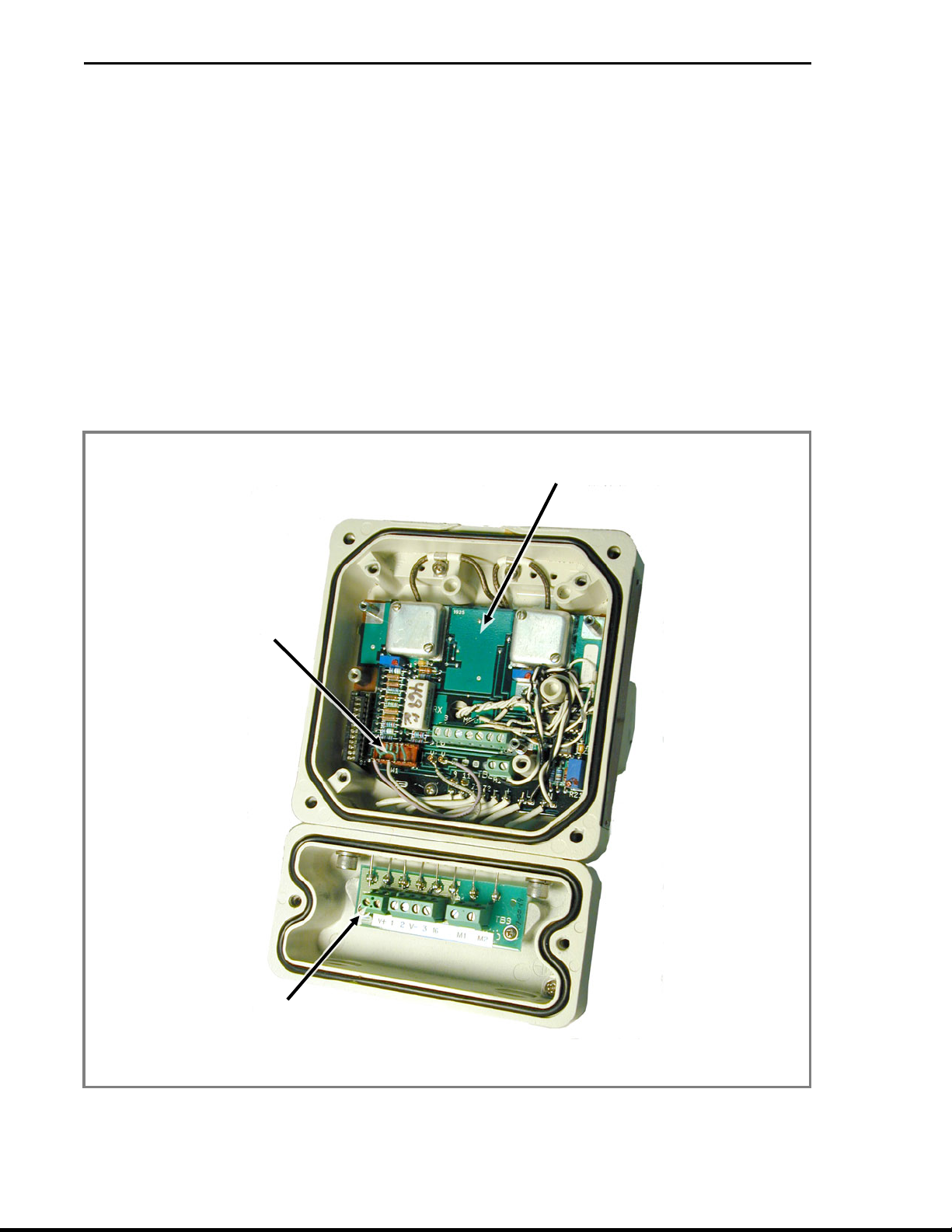
FIGURE 1-1. ELECTRONICS COMPARTMENT WITHOUT THE SIGNAL CONVERTER. . . . . . . . . . . 1-2
FIGURE 1-2. ELECTRONICS COMPARTMENT WITH THE SIGNAL CONVERTER . . . . . . . . . . . . . . 1-3
FIGURE 2-1. OUTLINE DIMENSIONS, 1" - 1-1/2" SIZES . . . . . . . . . . . . . . . . . . . . . . . . . . . . . . . . . . . 2-3
FIGURE 2-2. OUTLINE DIMENSIONS, 2" - 4" SIZES . . . . . . . . . . . . . . . . . . . . . . . . . . . . . . . . . . . . . . 2-4
FIGURE 2-3. OUTLINE DIMENSIONS, WITH SANITARY FITTINGS, 1" - 1-1/2" SIZES. . . . . . . . . . . . 2-5
FIGURE 2-4. OUTLINE DIMENSIONS, WITH SANITARY FITTINGS, 2" - 4" SIZES . . . . . . . . . . . . . . . 2-6
FIGURE 2-5. RECOMMENDED PIPING DIAGRAM . . . . . . . . . . . . . . . . . . . . . . . . . . . . . . . . . . . . . . . . 2-7
FIGURE 2-6. FLANGE BOLT TIGHTENING SEQUENCE . . . . . . . . . . . . . . . . . . . . . . . . . . . . . . . . . . . 2-9
FIGURE 2-7. MOUNTING DIAGRAM FOR 25 - 40 mm (1 - 1-1/2") SIZES . . . . . . . . . . . . . . . . . . . . . . 2-11
FIGURE 2-8. MOUNTING DIAGRAM FOR 50 - 100 mm (2 - 4") SIZES. . . . . . . . . . . . . . . . . . . . . . . . 2-12
FIGURE 2-9. TYPICAL MOUNTING DIAGRAM, SANITARY FITTINGS. . . . . . . . . . . . . . . . . . . . . . . . 2-13
FIGURE 2-10. GROUNDING PROCEDURE, CONDUCTIVE PIPE . . . . . . . . . . . . . . . . . . . . . . . . . . . 2-15
FIGURE 2-11. GROUNDING PROCEDURE, PIPE WITH INSULATED PIPE . . . . . . . . . . . . . . . . . . . 2-17
FIGURE 2-12. OUTLINE DIMENSIONS, GROUNDING RINGS. . . . . . . . . . . . . . . . . . . . . . . . . . . . . . 2-18
FIGURE 2-13. CUSTOMER CONNECTION BOX FOR INTERCONNECTION WIRING . . . . . . . . . . . 2-18
FIGURE 3-1. TYPICAL INSTRUMENT TAG . . . . . . . . . . . . . . . . . . . . . . . . . . . . . . . . . . . . . . . . . . . . . . 3-1
FIGURE 3-2. PRIMARY MOUNTED PC ASSEMBLY . . . . . . . . . . . . . . . . . . . . . . . . . . . . . . . . . . . . . . . 3-2
FIGURE 4-1. BASIC OPERATING PRINCIPLE . . . . . . . . . . . . . . . . . . . . . . . . . . . . . . . . . . . . . . . . . . . 4-1
FIGURE 5-1. SCHEMATIC FOR PRIMARY WIRING WHEN USING INTEGRAL CONVERTER. . . . . . 5-3
FIGURE 5-2. SCHEMATIC FOR PRIMARY WIRING WHEN USING REMOTE CONVERTER . . . . . . . 5-4
FIGURE 6-1. BASIC FLOWMETER PARTS . . . . . . . . . . . . . . . . . . . . . . . . . . . . . . . . . . . . . . . . . . . . . . 6-6
Table List
TABLE 1-1. CAL FACTOR & CAPACITY . . . . . . . . . . . . . . . . . . . . . . . . . . . . . . . . . . . . . . . . . . . . . . . . 1-10
TABLE 1-2. METER WEIGHT . . . . . . . . . . . . . . . . . . . . . . . . . . . . . . . . . . . . . . . . . . . . . . . . . . . . . . . . 1-10
TABLE 2-1. RECOMMENDED BOLT TORQUE . . . . . . . . . . . . . . . . . . . . . . . . . . . . . . . . . . . . . . . . . . . 2-9
TABLE 6-1. PRIMARY COIL RESISTANCE . . . . . . . . . . . . . . . . . . . . . . . . . . . . . . . . . . . . . . . . . . . . . . 6-4
TABLE 7-1. ANSI CLASS 125/150 GROUNDING RINGS. . . . . . . . . . . . . . . . . . . . . . . . . . . . . . . . . . . . 7-1
TABLE 7-2. GASKETS FOR GROUNDING RINGS . . . . . . . . . . . . . . . . . . . . . . . . . . . . . . . . . . . . . . . . 7-1
TABLE 7-3. STANDARD GASKETS FOR METER BODY . . . . . . . . . . . . . . . . . . . . . . . . . . . . . . . . . . . 7-2
TABLE 7-4. SPECIAL METALLIC GASKETS FOR METER BODY IN AREAS
WITH HIGH LEVEL OF RFI . . . . . . . . . . . . . . . . . . . . . . . . . . . . . . . . . . . . . . . . . . . . . . . . 7-2
TABLE 7-5. INTERCONNECTION CABLE . . . . . . . . . . . . . . . . . . . . . . . . . . . . . . . . . . . . . . . . . . . . . . . 7-2
INSTRUCTION BULLETIN 10D1477 CK-MAG MAGNETIC FLOWMETER
ii

READ FIRST
WARNING
INSTRUCTION MANUALS
Do not install, maintain, or operate this equipment without reading,
understanding and following the proper factory-supplied instructions
and manuals, otherwise injury or damage may result.
RETURN OF EQUIPMENT
All Flowmeters and/or Signal Converters being returned to the factory
for repair must be free of any hazardous materials (acids, alkalis,
solvents, etc). A Material Safety Data Sheet (MSDS) for all process
liquids must accompany returned equipment. Contact the factory for
authorization prior to returning equipment.
Read these instructions before starting installation;
save these instructions for future reference.
Contacting the Factory . . .
Should assistance be required with any of the company’s products, contact the following:
Telephone:
24-Hour Call Center
1-800-HELP-365
E-Mail:
ins.techsuppor[email protected]
10D1477 MAGNETIC FLOWMETER INSTRUCTION MANUAL
III

The NEMA 4X rating applies to the meter body and electronics enclosure only. The following
accessories (if supplied) may not meet NEMA 4X unless specifically ordered as NEMA 4X:
•meter flanges
•meter installation hardware: studs, nuts, bolts
•enclosure mounting hardware for pipe or wall mounting
•conduit hardware
This product is painted with a high performance epoxy paint. The corrosion protection provided by
this finish is only effective if the finish is unbroken. It is the users’ responsibility to "touch-up" any
damage that has occurred to the finish during shipping or installation of the product. Special attention
must be given to: meter flange bolting, pipe mounting of electronics, conduit entries and covers that
are removed to facilitate installation or repair. For continued corrosion protection throughout the
product life, it is the users’ responsibility to maintain the product finish. Incidental scratches and other
finish damage must be repaired and promptly re-painted with approved touch-up paint. Provide the
model number and size of your product to the nearest factory representative to obtain the correct
touch-up paint.
10D1477 MAGNETIC FLOWMETER INSTRUCTION MANUAL
I

1.0 INTRODUCTION
1.1 General
The series 10D1477 CK-MAGMagnetic Flowmeter is an electro-magnetic liquid flow rate detector.
The meter uses the characteristics of a conductive liquid to generate an induced signal voltage,
directly proportional to flow rate, as the liquid passes capacitively coupled measuring electrodes. The
resultant voltage is applied to a solid state electronics package that conditions it to an output signal
compatible with conventional receiving equipment.
The standard meter design provides a compact, very low power, obstructionless primary metering
element that bolts between flanges in a process pipeline. Pressure losses in this type of meter are
reduced to levels occurring in equivalent lengths of equal diameter pipeline, thus reducing or
conserving pressure source requirements as compared to other metering methods. The compact size
of the meter results in a light-weight unit that requires no additional support other than that normally
used on pipe runs.
The Series 10D1477 CK-MAG complies with 3-A Sanitary Standards For Flowmeters For Milk and
Milk Products, Number 28-03*. As an option, for 3-A Sanitary applications, the CK-MAG can be
supplied with TRI-CLAMP®sanitary adaptors for connection to the customer’s sanitary tubing
system.
This Flowmeter can be used to meter either clean or dirty liquids. The meter may be used without
regard to the heterogeneous consistency of the measured liquid and is as independent of the
tendency to plug or foul as the pipeline in which it is mounted. By design, the ceramic spool of the
meter body is wetted (electrodes are non-wetted). This design will accommodate most acids, bases,
water and aqueous solutions.
Viscosity and density of the metered liquid have no effect on the measurement accuracy of the meter
and, therefore, signal compensation is not required. Metering limitations are confined to a minimum
threshold of electrical conductivity inherent to the liquid being metered. The degree of liquid conduc-
tivity has no effect upon the metering accuracy (as long as it is greater than the minimum level). The
liquid temperature and pressure are limited to the meter material specification limit.
The meter body is a sealed section that bolts between the customer’s pipe line flanges. The
measuring electrodes are encased behind the metering tube. For accurate results, the meter bore
diameter must be centered in the pipeline. For the larger size meters, spacer sleeves are slipped
over the flange mounting bolts. The smaller size meters use a unique centering device to center the
meter. The centering device is shown in Figure 2-6.
* 3-A Sanitary Standards are formulated by the International Association of Food Industry Suppliers (IAFIS), the International
Association for Food Protection (IAFP), the United States Public Health Service (USPHS) and the Dairy Industry Committee
(DIC). The 3-A Sanitary Standards, Inc. Administrative Council verifies compliance to these standards and authorizes the
use of the 3-A Symbol.
10D1477 MAGNETIC FLOWMETER INSTRUCTION MANUAL
1-1

With the exception of the CMF/BUFFER board, the associated electronics package is called the
signal converter and is remotely mounted. Figure 1-1 shows the electronics housing used in conjunc-
tion with a remote signal converter.
The remote mounted signal converter is beneficial for:
1) high vibration areas
2) high process temperatures
The Signal Converter contains a magnet driver unit that is used to power the meter’s magnet coils.
The steady state magnetic field principle, referred to as the MAG-X design concept, provides
optimum zero point stability at an optimized frequency which is a submultiple of the power line
frequency.
For additional information on the electrical operation of the meter refer to Section 4.0 Functional
Description in this instruction manual and the instruction manual supplied with the signal converter.
FIGURE 1-1. 10D1477S ELECTRONICS COMPARTMENT
PRIMARY CMF/BUFFER BOARD
CUSTOMER
CONNECTION
BOARD
W1 CONNECTOR
10D1477 MAGNETIC FLOWMETER INSTRUCTION MANUAL
1-2

1.2 Model Number Breakdown
Refer to the data sheet or the data tag on the equipment for the model number of the instrument
furnished. The details of a specific number are shown on the following pages:
10D1477 MAGNETIC FLOWMETER INSTRUCTION MANUAL
1-3

1.2.1 Model 10D1477S
10D 1477 SH__A 1 9_Y_3 A 1 1 2_
Engineering File Reference
Obstructionless Magnetic Flowmeter 10D
Design Designation
CK-MAG Design (non-flanged insert)
MAG-X Driver Circuit
1477
Design Level
Letter assigned by the factory; Constant meter
factor/size & Microprocessor Signal Converter
S
Liner Material
Ceramic Spool H
Meter Size, Inches (mm)
1 (25)
1-1/2 (40)
2 (50)
3 (80)
4 (100)
09
11
12
14
15
Flange Standard/Pressure Rating
(Meter clamps between customer’s pipeline flanges)
ANSI Class 150
ANSI Class 300
Sanitary TRI-CLAMP Fittings *
P
Q
1
Electrode Construction (non-wetted)
Encased within spool body A
Electrode Type
Capacitive Pickup 1
Flange Material
Flangeless Design 9
Note: Certification option "K" is not mutually exclusive;
i.e. an FM approved meter can be supplied for sanitary applications
* Must be approved by Product Manager. No grounding rings or mounting hardware supplied.
10D1477 MAGNETIC FLOWMETER INSTRUCTION MANUAL
1-4

1.2.1 Model 10D1477S (continued)
10D 1477 SH__A 1 9_Y_3 A 1 1 2_
Certifications
Without FM Approval (General Purpose)
FM Approved
Primary Flowmeter & remote-mounted Signal Converter;
Non-incendive for Cl I, Div 2, Gp.A,B,C & D; Outdoor Hazardous
Locations, NEMA-4X. Accidental Submergence,
30 ft H2O/48 h (9 m H2O/48 h)
A
K
Power Requirements
Remote Converter with separate model number Y
Enclosure Classification
IEC 529 IP65, NEMA 4X
Accidental Submergence, IEC 529 IP67, NEMA 4X
30ft H2O/48 hr (9 m H2O/48 hr)
1
5
Liquid Temperature Range
w/ Remote Converter to 120oC (248oF) 2
Output Current
No Output Signal Required, Remote Mounted Converter A
Output Options
No Scaled Output Required 1
Communication Mode Over Data Link
Not Applicable 1
Coil Drive Frequency
15 Hz (@ 60 Hz power line frequency) 2
Additional Options
None
HARTProtocol
2
3
10D1477 MAGNETIC FLOWMETER INSTRUCTION MANUAL
1-5

1.3 Specifications
Power Requirements See Section 1.2 Model Number Breakdown
Power Consumption Refer to Signal Converter instruction manual
50XM1000N for power input requirements
Flowmeter Characteristics
Meter Size/Flow Capacity See Table 1-1
Span Factory set at specified range between extremes
listed in Table 1-1; can be field adjusted.
Rangeability 100:1
Minimum Liquid Conductivity To 0.05 µS/cm (depending on liquid velocity and
viscosity)
System Accuracy:
Applies from 2 to 100% of
CAL FACTOR.
1% of rate
RFI Protection Class 3-abc-0.5% (30 V/m-20 to 1000 MHz) Per
SAMA Standard PMC 33.1-1978. Standard with
integral Converters.
Environmental Limits
Enclosure Classification with
or without Signal Converter
IEC 529 IP65, NEMA 4X
Accidental Submergence IE 529 IP67, NEMA 4X,
30 feet H2O/48 h (9 m H2O/48 h)
10D1477 MAGNETIC FLOWMETER INSTRUCTION MANUAL
1-6

Temperature Limits
Primary Temperature Limits With
Remote Mounted Converter
Maximum liquid temperature is 120oC (248oF)
and maximum liquid temperature is a function of
ambient temperature:
Maximum oC liquid = 140 - maximum oC ambient
Maximum oF liquid = 316 - maximum oF ambient
NOTE
Process liquid temperature may not exceed 120oC (248oF)
Thermal Shock positive temp change, 100oC
negative temp change, 70oC
CAUTION
The temperature gradient between the liquid and the ceramic spool
should not exceed 100o C when increasing the temperature,
or 70oC when cooling, to prevent cracking. For example, if the ce-
ramic is at a temperature of 20o C, liquids at 120o C can safely be
handled. However, if the liquid temperature is 120oC, the ceramic
spool should be stabilized for approximately 5 minutes at 60o C be-
fore allowing it to decrease to 20oC. This is especially important
when following SIP* (Steam-in-place) procedures.
* SIP procedures per pharmaceutical industry.
Pressure Rating: MPa (psi)
Temperature
Meter Size 38oC (100o F) 120oC (248oF)
25 to 80mm
(1" - 3")
5.11 MPa
(740 psi)
4.62 MPa
(669 psi)
100mm
(4")
2.00 MPa
(285 psi)
1.66 MPa
(240 psi)
Vacuum Limit full vacuum at 120oC (248oF)
Meter Calibration Factor specified on primary data tag (equal to max flow
capacity in engineering units). This factor is
equivalent to a flow velocity of 33.33 ft/s in the
metering tube.
10D1477 MAGNETIC FLOWMETER INSTRUCTION MANUAL
1-7

Physical Characteristics
Outline Dimensions, Magnetic
Flowmeter with or without
integral Signal Converter Standard with Sanitary Fittings
25 - 40 mm (1 - 1-1/2") See Figure 2-1 See Figure 2-3
50 - 100 mm (2 - 4") See Figure 2-2 See Figure 2-4
Remote Mounted Signal
Converter
See Signal Converter Instruction Bulletin
Conduit Connections (2) 1/2" NPT internally threaded entrances in pri-
mary junction box
Meter Weight
Remote Mounted Signal
Converter
See Signal Converter Instruction Bulletin
Materials of Construction
Meter Body (Spool) Ceramic, 99.5% Alumina
Electrode Assemblies
(non-wetted)
Capacitive Pickup
Meter Housing carbon steel, all welded construction, epoxy finish
Housing End Rings 304 sst
Electronics Housing die cast aluminum, epoxy finish, 316 sst attach-
ment screws, 1/2 NPT conduit connections,
gasketed covers
Installation Kit includes 2 gaskets, mounting studs and nuts,
flange adaptor device(s) as required.
Exception: Sanitary TRI-CLAMP Fittings
Meter is preassembled; all mounting hardware
(studs and nuts) and flanges are stainless steel.
Gaskets are TEFLON-FEP (Virgin). Gasket
manufacturer must provide certificate of
compliance as proof of and compliance with 3A
Sanitary Standards, Class-I material.
10D1477 MAGNETIC FLOWMETER INSTRUCTION MANUAL
1-8

TABLE 1-1. CAL FACTOR and CAPACITY
FLOW RANGES
0 to VALUE TABULATED
SIZE
CAL
FACTOR * MINIMUM MAXIMUM
mm inches gpm gpm lpm gpm lpm
25 1 53.67 4.8 20.0 60.0 200.0
40 1-1/2 161.0 14.4 60.0 180.0 600.0
m3/H m3/H
50 2 268.3 24.0 6.0 300.0 60.0
80 3 805.1 72.0 18.0 900.0 180.0
100 4 1073.0 96.0 24.0 1200.0 240.0
10D1477 MAGNETIC FLOWMETER INSTRUCTION MANUAL
1-9

2.0 INSTALLATION
2.1 Inspection
All Model 10D1477 CK-MAG magnetic flowmeters are shipped in heavy duty containers. The packag-
ing used for CK-MAG protection is certified for air shipment by the Container Testing Laboratory. An
itemized list of all items included in the shipment is attached to the shipping container.
The shipment will generally consist of the magnetic flowmeter and appropriate mounting hardware kit
and a remote mounted signal converter with a 30 foot (9 m) long interconnection cable. (Signal cable
lengths up to 100 feet (30 m) can be supplied, when specified.)
The mounting hardware kit for the standard CK-MAG includes:
1) 4 (or 8) threaded studs and nuts,
2) 2 gaskets, and
3) appropriate flange adapter components, if specified.
NOTE
The centering device (see Figure 2.7) or adapter sleeves (see Fig-
ure 2-7) required for the particular meter installation are supplied
with all US orders.
When a sanitary CK-MAG is specified, it is provided with TRI-CLAMP sanitary adapters assembled
to the meter with all stainless steel (studs and nuts) hardware as shown in Figures 2-3 and 2-4.
Inspect all items included in the shipment immediately for indications of damage which may have
occurred during shipment. All damage claims should be reported to the shipping agent involved
before attempting to install or operate the equipment.
The proper use of the items included in the mounting hardware kit and the proper employment of
them during installation is necessary to maintain a valid instrument warranty. (An installation and
warranty tag is furnished with the mounting hardware kit that provides the basic information essential
for proper meter installation.)
Following inspection of the shipment contents, it is suggested that all items be carefully replaced in
the shipping container for transit to the installation site. The use of normal care in the handling and
installation of this equipment will contribute substantially toward satisfactory performance.
10D1477 MAGNETIC FLOWMETER INSTRUCTION MANUAL
2-1

2.2 Location
The Flowmeter is suitable for either indoor or outdoor installation. When selecting the installation
site, consideration should be given to the ambient and process temperature limits, as stated in
Specifications Section 1.3. The standard meter is rated NEMA 4X, (dust tight and watertight) and will
therefore withstand rain and hose down. If flooding is a problem, the optional "Accidental Submer-
gence" flowmeter is suited for applications where occasional submergence to 30 ft H2O/48 h
(9 m H2O/48 h) may occur.
For proper operation, it is recommended that the meter not be installed within the immediate
proximity of heavy induction equipment such as pumps, motors, etc.
Outline dimensions of the flowmeter are given in Figures 2-1 through 2-4. When applicable, allow
access for occasional servicing of the flowmeter primary. At least 5 inches of overhead clearance is
required for cover removal.
The installation site must be provided with a source of 120 V ac, 50/60 Hz (220/240 V ac, 50/60 Hz
optional) single phase line power. Power requirements for the particular magnetic flowmetering
system are given on the instrument data tag. The power source must have an external disconnect
and suitable fuse (or circuit breaker) as shown on the applicable interconnection diagram. System
interconnection diagrams are provided in the instruction manual supplied with the particular signal
converter.
2.3 Mounting
2.3.1 Meter Orientation
The Model 10D1477 CK-MAG magnetic flowmeter may be installed in horizontal, vertical or sloping
pipe runs. However, precautions must be taken to assure that the meter is filled at all times during
measurement. A vertical installation, with the pipe line carrying liquid upwards, assures a filled
hydraulic line under low flow rate conditions and also minimizes wear on the metering tube by
abrasive grit. Horizontal installations should be made with the meter in the lower section of a pipeline
to assure a filled meter condition.
The electronic housing of the meter should be top oriented for horizontal or sloping installations. This
aligns the meter electrodes in a lateral plane, a position that eliminates the possibility of entrained air
acting as an electrode insulator. Electrodes must not be on "top" when the meter is horizontally
mounted.
The CK-MAG magnetic flowmeter must be oriented in accordance with the direction of process flow,
as indicated by the FLOW arrow on the meter data tag. Elbows should be located a minimum of three
pipe diameters upstream from the meter. Control valves should be located on the downstream side
of the meter. Control valves upstream of the meter can create turbulence that result in air pockets
and may effect the meter’s accuracy or cause its output to be noisy. If for some reason the control
valve cannot be located downstream from the meter, a minimum of ten pipe diameters upstream are
required between the meter and the control valve. The requirements for control valves also applies to
pumps. Pipe diameters are measured from the centerline of the meter to the nearest edge of the
device, as shown in Figure 2-5. For higher accuracy requirements, use twice the number of pipe
diameters referenced. See Figure 2-5 for recommended piping diagram.
10D1477 MAGNETIC FLOWMETER INSTRUCTION MANUAL
2-2

FIGURE 2-1. OUTLINE DIMENSIONS, 1" - 1-1/2" SIZES
10D1477 MAGNETIC FLOWMETER INSTRUCTION MANUAL
2-3

FIGURE 2-2. OUTLINE DIMENSIONS, 2" - 4" SIZES
10D1477 MAGNETIC FLOWMETER INSTRUCTION MANUAL
2-4

FIGURE 2-3. OUTLINE DIMENSIONS, WITH SANITARY FITTINGS,
1" - 1-1/2" SIZES
Ref.
10D1477 MAGNETIC FLOWMETER INSTRUCTION MANUAL
2-5
Table of contents
Other ABB Measuring Instrument manuals

ABB
ABB MagMaster User manual

ABB
ABB GLA132 Series User manual

ABB
ABB NETA-21 User manual

ABB
ABB COPA-XM 3000 Series User manual

ABB
ABB Totalflow G5 Series User guide

ABB
ABB CoriolisMaster FCM2000 Training manual

ABB
ABB SACE Emax 2 User manual

ABB
ABB Levelmeter 2000 User manual

ABB
ABB SM1000 User manual

ABB
ABB FV4000-VT4 User manual
Popular Measuring Instrument manuals by other brands

NORTHROP GRUMMAN
NORTHROP GRUMMAN Patara I user manual

PCB Piezotronics
PCB Piezotronics J353B18 Installation and operating manual

Endress+Hauser
Endress+Hauser Analytik Jena Biometra TS1 ThermoShaker Short manual

PAT
PAT DS 350 / 1334 GRAPHIC Operator's manual

GF
GF SG 160 instruction manual

Chemtrac
Chemtrac HydroACT Quick start up guide