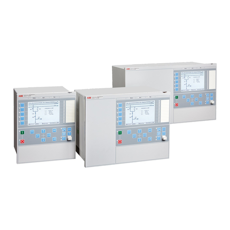
ABB JDF300 User manual

—
ABB MEASUREMENT & ANALYTICS | OPERATING INSTRUCTION
JDF300
Field indicator with
FOUNDATION Fieldbus communication
The field indicator JDF300 provides
simple and low cost remote
indication of a process variable on
an easy to read LCD display.
Measurement made easy
Introduction
The present manual provides information on
installing, operating, troubleshooting the field
indicator JDF300. Every section of the present
manual is specifically dedicated to the specific
phase of the field indicator lifecycle starting from
its receipt and identification, passing to the
installation, to the electrical connections, to the
configuration and to the troubleshooting and
maintenance operations.
The present manual can be used for JDF300 field
indicator.
The new JDF300 Foundation Fieldbus indicator
provides remote visibility for up to 8 variables,
subscribed from the bus (publisher/subscriber) or
directly written by the Host (client/server).
Each individual variable/input to be displayed can
be remotely selected through FF protocol or locally
selected operating on the housing push button or
through the local display menu: such delocalized
configuration capabilities saves time and greatly
improve productivity.
In addition to its standard function of Field
Indicator, the JDF300 is a Link Master device and
offers a set of Control Function Blocks improving its
calculation capability available for distributed
control strategy solutions.
For more information
Further publications for JDF300 are available
for free download from:
www.abb.com/measurement
or by scanning this code:
Search for or click on:
Datasheet
Operating Instruction
—
JDF300 field indicator

2JDF300 | FIELD INDICATOR | OI/JDF300-EN REV. B
Contents
1 Health & Safety ............................. 4
General Safety Information ........................ 4
Improper use...................................... 4
Technical limit values .............................. 4
Warranty provision ................................ 4
Use of instructions ................................ 4
Operator liability ...................................5
Qualified personnel ................................5
Returning devices ..................................5
Disposal ...........................................5
Information on WEEE Directive 2012/19/EU
(Waste Electrical and Electronic Equipment) .........5
Transport and storage ..............................5
Safety information for electrical installation .........5
Safety information for inspection and
maintenance .......................................5
Cyber security .....................................5
2 Field indicator overview......................6
Field indicator components overview............... 6
3 Product identification .......................6
Nameplate ........................................ 6
.....................7
4 Handling and storage ........................7
5 Installation..................................7
General ............................................7
IP protection & designation .........................7
General installation information.................... 8
Field indicator factory configuration
consideration ...............................8
Hazardous area considerations................8
Warning General risk for JDF300 used in zone 0 .8
Installing JDF300 field indicator.................... 8
Bracket mounting.............................8
Securing the housing cover in flameproof areas.9
6 Field indicator wiring ........................9
Cable connection.................................. 9
Supply requirement ...............................10
Grounding ........................................10
Wiring procedure..................................10
7 Electronic board ............................11
Fault Protection ...................................11
On board switches ................................11
8 Display.....................................12
Configuration of the field indicator using the
10
Installing/Removing the LCD display ...............12
Integral Display Rotation...........................12
Display Layout ....................................12
Configuration of the field indicator using the optional
........14
Local device menu.................................14
Local menu details ...........................14
Local operator menu ..............................14
Configuration of the field indicator using the housing
push buttons......................................15
The Write Lock button .......................15
The Z and S functions ........................15
Autoscrolling Function .......................16
Squawk Function ............................ 17
9 Device Application Process (DAP) blocks .....18
Resource Block (RB) ...............................18
Overview ....................................18
Resource block mapping .....................19
HMI Transducer Block (HMITB) .................... 22
Overview ....................................22
Block diagram ...............................22
Description..................................22
HMITB mapping .............................23

JDF300 | FIELD INDICATOR | OI/JDF300-EN REV. B 3
10 Control Application Process (CAP) blocks ... 24
Multiple Analog Output Function Block (MAO)...... 24
Overview ....................................24
Block diagram ...............................24
Description..................................24
MAO block mapping .........................25
Diagnostic ..................................26
...............27
Overview ....................................27
Block diagram ...............................27
Description..................................27
Equations ...................................28
Configuration hints ..........................28
Block mapping ..............................29
Diagnostic ..................................32
OUT status . . . . . . . . . . . . . . . . . . . . . . . . . . . . . . . . . . 32
Troubleshooting .............................32
Arithmetic Function Block (AR).................... 33
Overview ....................................33
Block diagram ...............................33
Description..................................33
Equations ...................................34
Configuration hints ..........................35
Block mapping ..............................35
Diagnostic ..................................37
OUT status . . . . . . . . . . . . . . . . . . . . . . . . . . . . . . . . . . 37
Troubleshooting .............................37
Input Selector Function Block (IS) ................. 38
Overview ....................................38
Block diagram ...............................38
Description..................................38
Equations ...................................39
Configuration hints ..........................39
Block mapping ..............................40
Diagnostic ..................................41
OUT status . . . . . . . . . . . . . . . . . . . . . . . . . . . . . . . . . . 41
Troubleshooting .............................41
Control Selector Function Block (CS) .............. 42
Overview ....................................42
Block diagram ...............................42
Description..................................42
Equations ...................................42
Configuration hints ..........................42
Block mapping ..............................43
Diagnostic ..................................44
OUT status . . . . . . . . . . . . . . . . . . . . . . . . . . . . . . . . . .44
Troubleshooting .............................44
11 Maintenance .............................. 45
Returns and removal.............................. 45
Basic maintenance activities ..................... 45
12 Hazardous Area considerations............. 46
Ex Safety aspects and IP Protection (Europe) ...... 46
approval. ........................................48
13 Requirements for installation and use in US and
Canada ................................... 49
General .......................................... 49
Environmental Conditions ........................ 49
Instructions for cleaning.......................... 49
Insulation for secondary circuits derived from main
circuits of overvoltage category II up to 300 V...... 49
Ex Safety aspects and IP Protection (USA) ......... 49
Applicable standards ............................. 49
Classifications ................................... 49
Special conditions................................50
Ex Safety aspects and IP Protection (Canada) ......50
Applicable standards .............................50
Classifications ................................... 50
Special conditions................................50
FM marking and entities ...........................51

4JDF300 | FIELD INDICATOR | OI/JDF300-EN REV. B
1 Health & Safety
General Safety Information
The Safety section provides an overview of the safety aspects
to be observed for operation of JDF300. The device has been
constructed in accordance with the state of the art and is
operationally safe. It has been tested and left the factory in
perfect working conditions. The information in the manual, as
well as the applicable documentation and certificates, must be
observed and followed in order to maintain this condition
throughout the period of operation.
Full compliance with the general safety requirements must be
observed during operation of the device. In addition to the
general information, the individual sections in the manual
contain descriptions of processes or procedural instructions
with specific safety information. Only by observing all of the
safety information can you reduce to the minimum the risk of
hazards for personnel and/or environment. These instructions
are intended as an overview and do not contain detailed
information on all available models or every conceivable event
that may occur during setup, operation, maintenance work and
dismantling. For additional information, or in the event of
specific problems not covered in detail by these operating
instructions, please contact the manufacturer. In addition, ABB
declares that the contents of this manual are not part of any
prior or existing agreements, commitments or legal
relationships; nor are they intended to amend these. All
obligations of ABB arise from the conditions of the relevant
sales agreement, which also contains the solely binding
warranty regulations in full. These contractual warranty
provisions are neither extended nor limited by the information
provided in this manual.
Only qualified and authorized specialist personnel should be
charged with installation, electrical connection,
commissioning and maintenance of the field indicator.
Qualified personnel are persons who have experience in
installation, electrical connection, commissioning and
operation of the field indicator or similar devices and hold the
necessary qualifications such as:
•Training or instruction, i.e., authorization to operate and
maintain devices or systems according to safety
engineering standards for electrical circuits, high
pressures and aggressive media
•Training or instruction in accordance with safety
engineering standards regarding maintenance and use of
adequate safety systems.
For safety reasons, ABB draws your attention to the fact that
only sufficiently insulated tools conforming to DIN EN 60900
may be used. Since the field indicator may form part of a safety
chain, we recommend replacing the device immediately if any
defects are detected. In case of use in Hazardous Area non
sparking tools only must be employed. In addition, you must
observe the relevant safety regulations regarding the
installation and operation of electrical systems and the relevant
standards, regulations, guidelines about explosion protection.
Improper use
It is prohibited to use the device for the following purposes:
• As a climbing aid, e.g., for mounting purposes
• As a support for external loads, e.g., as a support for pipes.
• Adding material, e.g., by painting over the name plate or
welding/soldering on parts
•Removing material, e.g., by drilling the housing.
Repairs, alterations, and enhancements, or the installation of
replacement parts, are only permissible as far as these are
described in the manual. Approval by ABB must be requested
for any activities beyond this scope. Repairs performed by
Technical limit values
The device is designed for use exclusively within the values
stated on the name plates and within the technical limit values
specified on the data sheets.
The following technical limit values must be observed:
• The maximum ambient operating temperature may not be
exceeded.
• The housing protection type must be observed.
• The supply voltage and power
Warranty provision
Using the device in a manner that does not fall within the scope
of its intended use, disregarding this manual, using
underqualified personnel, or making unauthorized alterations,
releases the manufacturer from any liability for any resulting
damage. This makes the manufacturer’s warranty null and void.
Use of instructions
The signal word ‘DANGER’ indicates an imminent danger.
Failure to observe this information will result in death or
severe injury.
The signal word ‘WARNING’ indicates an imminent danger.
Failure to observe this information may result in death or
severe injury.
The signal word ‘CAUTION’ indicates an imminent danger.
Failure to observe this information may result in minor or
moderate injury.
The signal word ‘NOTICE’ indicates potential damage to
material or its surrounding area.
This message indicates operator tips or particularly
useful information. It does not indicate a dangerous or
damaging situation.
DANGER
WARNING
CAUTION
NOTICE
IMPORTANT
CAUTION

JDF300 | FIELD INDICATOR | OI/JDF300-EN REV. B 5
Operator liability
The operators must strictly observe the applicable national
regulations with regard to installation, function tests, repairs,
and maintenance of electrical devices.
Qualified personnel
Installation, commissioning, and maintenance of the device
may only be performed by trained specialist personnel who
have been authorized by the plant operator. The specialist
personnel must have read and understood this safety manual
and comply with its instructions.
Returning devices
Use the original packaging or suitably secure shipping package
if you need to return the device for repair.
According to EU guidelines and other local laws for hazardous
materials, the owner of hazardous waste is responsible for its
disposal. The owner must observe the proper regulations for
shipping purposes. All devices sent back to ABB must be free
from any hazardous materials (acids, alkalis, solvents, etc.).
Disposal
ABB actively promotes environmental awareness and has an
operational management system that meets the requirements
of EN ISO 9001:2015, EN ISO 14001:2015 and EN ISO 18001:2015.
Our products and solutions are intended to have minimum
impact on the environment and people during manufacturing,
storage, transport, use and disposal. This includes the
environmentally friendly use of natural resources. ABB conducts
an open dialog with the public through its publications. This
product/solution is manufactured from materials that can be
reused by specialist recycling companies.
Information on WEEE Directive 2012/19/EU
(Waste Electrical and Electronic Equipment)
This product or solution is subject to the WEEE Directive
2012/19/EU or corresponding national laws. Starting from
August 15th 2018, electrical and electronic equipment marked
as unsorted municipal waste. Waste of electrical and electronic
equipment (WEEE) shall be treated separately using the
national collection framework available to customers for the
return, recycling and treatment of WEEE.
Transport and storage
After unpacking the field indicator, check the device for
transport damage. Check the packaging material for
accessories. During intermediate storage or transport, store
the field indicator in the original packaging only.
For information on permissible ambient conditions for storage
and transport, see “Technical data”. Although there is no limit
on the duration of storage, the warranty conditions stipulated
on the order acknowledgment from the supplier still apply.
Safety information for electrical installation
Electrical connections may only be established by authorized
specialist personnel in accordance with the electrical circuit
diagrams. The electrical connection information in the manual
must be observed; otherwise, the applicable protection type
may be affected. Ground the measurement system according
to requirements.
Safety information for inspection and
maintenance
There is no EMC protection or protection against accidental
contact when the housing cover is open. There are electric
circuits within the housing which are dangerous if touched.
Therefore, the auxiliary power must be switched off before
opening the housing cover.
Corrective maintenance work may only be performed
by trained personnel.
• Before removing the device, remove power supply.
• Check whether hazardous materials have been used in the
surroundings before opening the device. Residual
amounts of hazardous substances may still be present in
the device and could escape when the device is opened.
• Within the scope of operator responsibility, check the
inspection.
Cyber security
Disclaimer
This product is designed to be connected to and to
communicate information and data via a network interface. It is
operator’s sole responsibility to provide and continuously
ensure a secure connection between the product and your
network or any other network (as the case may be). Operator
shall establish and maintain any appropriate measures (such as
but not limited to the installation of firewalls, application of
authentication measures, encryption of data, installation of
its system and the interface against any kind of security
breaches, unauthorized access, interference, intrusion, leakage
and/or theft of data or information.
ABB and its affiliates are not liable for damages and/or losses
related to such security breaches, any unauthorized access,
interference, intrusion, leakage and/or theft of data or
information.
Communication protocol specific
The FOUNDATION Fieldbus protocol is an unsecured protocol,
such as the intended application should be assessed to ensure
that these protocols are suitable before implementation.
WARNING

6JDF300 | FIELD INDICATOR | OI/JDF300-EN REV. B
2 Field indicator overview
Field indicator components overview
Figure 1 Field Indicator components
3 Product identification
Nameplate
The instrument is identified by the plates shown below.
The Nameplate provides information concerning: product code, output signal, tag and product serial number (see Ref. A).
Please refer to this number when making enquiries.
The Safety Marking plate provides information of Ex protection; it is filled with necessary Ex information only when the indicator is
for Hazardous Area installation (see Ref. B).
Local keys below label
FM18CA0110X - FM18US0231X
Figure 2 Product identification
HMI display with keypad
(L1 option)
Terminal blockCommunication board
Ref. A)
Ref. B)

JDF300 | FIELD INDICATOR | OI/JDF300-EN REV. B 7
JDF300 field indicator is in compliance with EMC 2014/30/EU.
The certification plate (ref.A) shown here is issued by ABB S.p.A,
22016 Tremezzina, Italy, with the numbers:
• FM 18 ATEX 0054X Ex db
• FM 18 ATEX 0055X Ex ia
• FM 18 ATEX 0056X Ex ic
• IECEx FME 18.0004X Exia, Ex db, Ex ic
• FM 18 US 0231X (IS, XP, NI, DIP) US
• FM 18 US 0110X (IS, XP, NI, DIP) CAN
Optional wired-on SST plate (I1)
The JDF300 can be supplied with the optional “Wired
on stainless steel plate” (figure 3) which is permanently laser
printed with a custom text specified in phase of order. The
available space consists in 4 lines with 32 characters per line.
The plate will be connected to the field indicator with a
stainless steel wire.
plate
4 Handling and Storage
The instrument does not require any special precautions during
handling although normal good practice should be observed.
The instrument does not require any special treatment if stored
as dispatched and within the specified ambient conditions.
There is no limit to the storage period, although the terms of
guarantee remain as agreed with the Company and as given in
the order acknowledgement.
Model JDF300 Storage temperature limits
With LCD display
5 Installation
General
Study these installation instructions carefully before
proceeding.
Failure to observe the warnings and instructions may cause a
malfunction or personal hazard. Before installing the field
indicator, check whether the device design meets the
requirements of the measuring point from a measurement
technology and safety point of view. This applies in respect of:
• Environment corrosion
• Explosion protection certification
• Temperature
• Operating voltage and current
In addition, the relevant directives, regulations, standards, and
accident prevention regulations must be observed (e.g., VDE/
VDI 3512, DIN 19210, VBG, Elex V, etc.). As far as possible, the
setup should be free from critical ambient conditions such as
extreme temperatures, vibrations, or shocks.
IMPORTANT
If unfavorable ambient conditions cannot be
avoided for reasons relating to building structure,
measurement technology, or other issues, product
quality may be affected.
IP protection & designation
The field indicator is dust and sand tight and protected against
spray water effect as defined by IEC60529 to IP66, IP67 or by
NEMA 250 Type 4X.
The first number indicates the protection of the electronics
against the entry of foreign bodies, including dust.
dust). The second number indicates the type of protection
the integrated electronics have against the effects of
temporary immersion in water under standardized water
pressure and temporal conditions.
AAAAAAAAAAAAAAAAAAAAAAAAAAAAAAAA
BBBBBBBBBBBBBBBBBBBBBBBBBBBBBBBB
CCCCCCCCCCCCCCCCCCCCCCCCCCCCCCCC
DDDDDDDDDDDDDDDDDDDDDDDDDDDDDDDD

8JDF300 | FIELD INDICATOR | OI/JDF300-EN REV. B
...5 Installation
General installation information
Field indicator factory configuration consideration
The field indicator in your hands has been manufactured to
reflect the published specification. According to the user
requirements it is possible to customize TAG number and
device address.
Hazardous area considerations
The field indicator can be installed in hazardous area only if
certified. The certification plate is permanently fixed on the
field indicator housing. JDF300 can have the following
certifications:
INTRINSIC SAFETY Ex ia:
• ATEX Europe (code E1) approval
IP66, IP67.
• IECEx (code E8) approval
EXPLOSION PROOF:
• ATEX Europe (code E2) approval
IP66, IP67.
• IECEx (code E9) approval
INTRINSIC SAFETY Ex ic:
• ATEX Europe (code E3) type examination
IP66, IP67.
• IECEx (code ER) type examination
FM Approvals US (code E6) and
FM Approvals Canada (code E4):
• Explosionproof:
Class I, Division 1, Groups A, B, C, D; T4
Class II, III Division 1, Groups E, F, G; T4
• Flameproof (US): Class I, Zone 1 AEx db IIC T4 Gb
• Flameproof (Canada): Class I, Zone 1 Ex db IIC T4 Gb
• Intrinsically safe:
Class I, Zone 0 AEx ia IIC T6...T4 Ga (US)
Class I, Zone 0 Ex ia IIC T6...T4 Ga (Canada)
Class I, Division 1, Groups A, B, C, D, T6...T4
Class II, Division 1, Groups E, F, G, T6...T4
Class III
when connected per drawing 3KXP000074U0109
“FISCO Field Instrument”
• Energy limited (US):
Class I, Zone 2 AEx nC IIC T6...T4 Gc
• Energy limited (Canada):
Class I, Zone 2 Ex nC IIC T6...T4 Gc
• Nonincendive: Class I, Division 2, Groups A, B, C, D T6...T4
when connected per drawing 3KXP000074U0109
“FISCO Field Instrument”
• Type 4X, IP66, IP67 for all above markings.
COMBINED ATEX (code EW = E1 + E2 + E3), (code E7 = E1 +
E2)
COMBINED IECEx (code EI = E8 + E9 + ER), (code EH = E8 +
E9)
COMBINED FM Approvals US and Canada
• Intrinsically safe (code EA)
• Nonincendive (code EC)
COMBINED ATEX, FM and IECEx Approvals (code EN)
Model JDF300 enclosure contains aluminium and is
considered to present a potential risk of ignition by impact or
friction. Care must be taken into account during installation
and use to prevent impact or friction.
Installing JDF300 field indicator
The field indicator model JDF300 can be mounted directly a
wall using approriate fixing screws (not provided by the
manufacturer).
A mounting bracket for pipe mounting (2 in pipe) is also
available as an accessory. It is recommended to mount the
field indicator to prevent this from being source of possible
damage for unskilled operators.
Bracket mounting
Mounting bracket is available as standard please refer to
the relevant installation drawing below in mm (inch.):
Figure 4 Mounting bracket
WARNING

JDF300 | FIELD INDICATOR | OI/JDF300-EN REV. B 9
Securing the housing cover in flameproof areas
The front face of the field indicator housing features a locking
(see picture 5).
•
• Turn the locking screw counterclockwise to secure the
housing cover. This involves unscrewing the screw until the
screw head stops at the housing cover.
For Hazardous Areas installations, at least six (6) threads on
the cover must be engaged in order to meet flameproof
Figure 5 Locking screw position
6 Field indicator wiring
Cable connection
Observe the applicable regulations governing electrical
installation. Connections must only be established in a
lightening according to IEC 61326 (higher capacity must be
provided at the plant). Check that the existing operating
voltage corresponds to the needed voltage.
The same lines are used for both the power supply and output
signal. In case the surge protection option is present and the
field indicator is installed in a Hazardous area, the field
indicator has to be power supplied from a voltage source
isolated from mains (galvanic separation). Furthermore the
potential equalization for the entire powering cable must be
guaranteed since the intrinsic safety circuit of the field
indicator is grounded.
Electrical shock can result in death or serious injury. Avoid
contact with the leads and terminals. High voltage that may be
present on leads can cause electrical shock. Do NOT make
electrical connections unless the electrical code designation
agrees with the classification of the area in which the field
indicator is to be installed. Failure to comply with this warning
can result in fire or explosion.
To remove the LCD, unscrew the housing cover by turning it.
Unplug the LCD by pulling it out gently. On the field indicator
housing there are two connection ports for cable glands or
conduit fittings. These ports are protected with plastic plugs
for transit purpose. The unused port plastic plug must be
replaced for Hazardous Area installations with flameproof
(explosion proof) protection (see relevant warning). Depending
on the design supplied, the electrical connection is established
terminals are suitable for wire cross sections up to 2.5 mm2
(AWG 14).
With Category 3 field indicators for use in “Zone 2”, a
qualified cable gland for this type of protection must be
installed by the customer (see the section “Hazardous Area
Consideration”).
housing for this purpose. For field indicators with “Flameproof
enclosure” (Ex d) type of protection, the housing cover must be
secured using the locking screw. The screw plug that may have
been supplied with the field indicator must be sealed at the
plant using Molykote DX. The installer assumes responsibility
for any other type of sealing medium used. At this point, we
wish to draw your attention to the fact that increased force will
be required to unscrew the housing cover after an interval of
several weeks. This is not caused by the threads, but instead is
due solely to the type of gasket.
WARNING
IMPORTANT
IMPORTANT

10 JDF300 | FIELD INDICATOR | OI/JDF300-EN REV. B
...6 Field indicator wiring
...Cable connection
The field indicator can be connected in accordance with the
following configuration:
• Indicator only, i.e. coupled to the field indicator’s terminal
block.
Supply requirement
For signal/power connection use twisted, stranded pairs of
wiring no 18 to 22 AWG / 0.8 to 0.35 mm2 OD up to 6200 feet
(1900 m). Longer loops require larger wire. If a shielded
wire is used, the shield should be grounded only at one end,
not both ends. In case of wiring at field indicator end, use the
terminal located inside the housing marked with the
appropriate sign.
The JDF300 Field Indicator is a Bus Powered device with
Fieldbus Foundation output. The two wires of the bus have to
be connected as in the picture.
The JDF300 FF is not Polarity Sensitive.
Note. Avoid routing cables with other electrical cables (with
inductive load, etc.) or near large electrical equipment.
Grounding
Field indicator housing should be grounded or earthed in
accordance with national and local electrical codes.
Protective grounding terminals (PE) are available outside and/
or inside the housing. Both ground terminals are electrically
connected and the user can decide which one to use.
The most effective field indicator case grounding method is
direct connection to earth ground with impedance equal or less
of 5 ohm.
Figure 6 Field indicator grounding
Wiring procedure
Follow these steps to wire the field indicator:
• Remove the temporary plastic cap from one of the two
electrical connection ports located at both sides in the
upper part of the field indicator housing.
• These connection ports may have a ½ inch internal NPT or
M20 threads. Various adaptors and bushings can be fitted
to these threads to comply with plant wiring (conduit)
standards.
• Remove the housing cover of the “field terminals” side. In
remove the field indicator cover when power is applied to
the unit.
• Run the cable through the cable gland and the open port.
•
terminal without taking care of their polarity
• Plug and seal the electrical ports. Make sure that when the
installation has been completed, the electrical ports are
properly sealed against entry of rain and/or corrosive
vapors and gases.
Cables, cable glands and unused port plugs must be in
accordance with the intended type of protection (e.g.
intrinsically safe, explosion proof, etc.) and degree of
protection (e.g. IP6x according to IEC EN 60529 or NEMA Type
4x). See also the addendum for “EX SAFETY” ASPECTS AND
“IP” PROTECTION.
In particular, for explosion proof installations, remove the red
temporary plastic caps and plug the unused openings with a
plug certified for explosion containment
• If applicable, install wiring with a drip loop. Arrange the drip
loop so the bottom is lower than the conduit connections and
the field indicator housing.
•
housing and then continue to hand tighten until the cover
Proof) installation, lock the cover rotation by turning the set
nut (use the 2mm Allen key supplied with the field indicator).
•
A protective grounding connection is absolutely necessary
to insure personnel protection, to protect against surge (in
case of installation of this option) and to prevent explosions
in potentially explosive environment.Installing/Removing the
LCD display.
Integrated lightning protection (optional)
The field indicator housing must be connected using the
grounding terminal (PA), by means of a short connection with
the equipotential bonding. Equipotential bonding (minimum
diameter: 4 mm2 (AWG 12) is required throughout the cable
routing area. In case of field indicator with integrated lightning
protection (optional), the intrinsically safe circuit is connected
to the equipotential bonding for safety reasons.
Fieldbus line / Power supply
(polarity independent)
External ground
termination point
Internal ground
termination point
IMPORTANT
WARNING
WARNING

JDF300 | FIELD INDICATOR | OI/JDF300-EN REV. B 11
Test voltage withstand capability can no longer be ensured
when this protective circuit is used.
7 Electronic Board
Fault protection
The JDF300 FF electronic implements a special circuitry for the
fault current protection. Whenever a fatal failure occurs and the
current consumption increase over the 20 mA, this circuitry
provides to disconnect the device from the bus, in order to
preserve the rest of the bus that, otherwise, risks to drop down
all the other connected devices.
On board switches
On the electronic unit under the display there are 4 dip switches
with the following functionality:
• Switch 1 and 2 are reserved for future use
• Switch 3
START UP. When in ON position and COLD start is selected, it
means that when a new power cycle is executed the device
will be set to a predefined basic configuration.
Some parameters of the HMITB, RB and MAO blocks are
written to a well defined value while all the other function
blocks are set to their FF standard default (“Initial Values”).
Figure 7 Electronic board view
After the Cold Start the JDF300 is ready to work displaying the
value of MAO_IN1 (input 1) with its default Subtag and unit code
while the quality status is displayed as textual format. Refer to
the Block’s table at the end of this manual to see which
function. They are in Bold/italic/underlined (pink color).
The basic parameters set by the Cold start up are the following:
Cold start-up condition
MAO_Channel
“none”
HMITB_IN_ENABLED
HMITB_SEQUENCE
HMITB_NUM_STATUS_ENA
Switch 4 selects the simulation mode which is a mandatory
requirement for FF devices.
JDF300O can simulate only diagnostic conditions writing the
error to be simulated into “RB_FD_SIMULATE” (index 67).
However, this writing has effect only if the HW switch4 has
been previously moved in ON position (SIMUL MODE ENABLED).
IMPORTANT

12 JDF300 | FIELD INDICATOR | OI/JDF300-EN REV. B
8 Display
Configuration of the field indicator using
the optional integral LCD with keypad
(menu-controlled)
The integral LCD is connected on the field indicator electronic
board. It can be used to visualize the process measured
variables as well as to configure the display.
In addition, diagnostic information is provided. To access the
functionality of the LCD an activation procedure needs to be
carried out.
The keypad operability doesn’t require any activation
procedure.
Installing/Removing the LCD display
1 Unscrew the housing cover of the communication board/
LCD side.
With an Ex d / Flameproof design, please refer to the
section “Securing the housing cover with Ex d”.
2 Attach the LCD display. Depending on the mounting position
of the field indicator, the LCD display may be attached in four
If necessary, refer to the section “Securing the housing
cover with Ex d”.
Figure 8 Indicator side view with cover open
Integral Display Rotation
It is possible to mount the display in four different positions
To rotate the LCD, simply open the windowed cover (Hazardous
housing from the communication board. Reposition the
LCD connector according to the new desired position. Push
back the LCD module on the communication board. Be sure that
the 4 plastic fixing locks are properly in place.
IMPORTANT
IMPORTANT
IMPORTANT

JDF300 | FIELD INDICATOR | OI/JDF300-EN REV. B 13
Display Layout
The Display DOT matrix is split in 4 rows each reserved to display different data:
Row 1 displays:
• Device TAG, as a string of 8 characters
• Status Byte displayed as textual or numeric format. The choice between text or decimal number is user selectable
from the parameter “HMITB_NUM_STATUS_ENA” (index 36).
When textual format is selected, only the Quality of the Status byte is displayed as:
“GOODnc”
“GOODc “
“BAD “
“UNCERT”
When the numeric format is selected the code of the Status byte is displayed inside round brakets
• Device Address, as detected in the live list of the FF bus.
Row 2 is reserved to the display a number of 5 digit with decimal point plus sign representing the measure received at
the selected input of the MAO block..
Row 3 displays:
• Variable TAG, as a string of 11 characters to identify the displayed measure.
• Unit code of the displayed measure as a text of 8 characters
• The user can write the Variable TAG and its unit code of each of the 8 MAO Block inputs. Refer to the parameters
“HMITB_INPUT x TAG” and “HMITB_INPUT x Unit” (indexes from 17 to 32) where x goes from 1 to 8 identifying one of
the 8 MAO inputs.
Row 4 displays:
• Diagnostic error code of three digit size plus the NAMUR NE107 classification icon
• The MAO input actually selected with the additional indication if the value in input is coming from a linked source
upward block or variable i.e: “INxL” or if it is not linked but directly written to the MAO input i.e: “INxN” where x goes
from 1 to 8 depending by the selected input (i.e: IN3L or IN2N)
• The Lock symbol when the JDF300 is write locked.
• The symbol indicating that the Autoscrolling of the enabled inputs is active.
Variable’s TAG
(Subtag)
FF Device
Address
Variable’s
Value
Variable’s
Status Byte
Device TAG
Variable’s
Unit code
NAMUR_NE107
Icon
Diagnostic error
code
Displayed Input Device Write
Locked
SEQUENCE = ON
Variable’s scrolling
enabled

14 JDF300 | FIELD INDICATOR | OI/JDF300-EN REV. B
Configuration of the field indicator using the
optional integral LCD with keypad (menu-controlled)
The JDF300 Field Indicator is a Dot matrix LCD with a keypad of
4 buttons connected to the electronic board.
Gain access to the display by unscrewing the windowed
cover. Please observe the Hazardous area prescription before
proceeding with the cover removal.
The keypad operability doesn’t require any activation
procedure.
controlled configuration.
During the normal activity when the indicator is displaying
the value of the selected input variable, the buttons (1) and
(4), which have a related symbol in the bottom corners of the
display, when pressed enable their own function as follows:
• The Button (4) activate the display local device menu
prompting the menu “Easy Setup”.
• The Button (1) activate the display local operator menu.
Local device menu
The local menus allow the review and setting of the most
relevant device parameters without to access through the FF
protocols. It consists in 4 root menus each with more or less
submenus:
For details about above parameters available from the local
menus, refer to the Block Mapping tables (sections 9 and 10).
Local menu details
Once the display enter into the local menus, the following
details could be taken in account:
• The menu / submenu name is displayed above in the LCD
display.
• The number/line of the currently selected menu item is
displayed in the upper right of the LCD display.
• A scroll bar is located on the right edge of the LCD display
which shows the relative position of the currently selected
menu item within the menu.
• Both of the keys (1) and (4) can have various functions. The
meaning of these buttons is displayed below in the LCD
display above the respective button.
• You can browse through the menu or select a number
within a parameter value using both keys (2) and (3) . The
button (4) selects the desired menu item.
Button (1) functionalities Meaning
Exit Exit menu
Back Back one submenu
Cancel Exit without saving the selected parameter value
Next Select next position for entering numerical
values or letters
Button (4) functionalities Meaning
Select Select submenu/parameter
Edit Edit parameter
Ok Save selected parameter and display stored
parameter value
Local operator menu
Once pressed the Button 1, the local HMI enter in the local
operator menu consisting of three submenus where only the
first of the list “Diagnostics” is supported.
Selecting “Diagnostics” it is displayed the device status/health.
1 2
3 4
1 Language
2 Contrast
3 Auto Scrolling
4 Input Selection
1 Language
2 Contrast
3 Input Enable
4 Auto Scrolling
5 Input Selection
6 Quality Status
Format
1 Software revision
2 Hardware revision
3 HMI software
revision
1 Device revision
2 DD revision
3 PD_TAG
4 Device Class
5 Device ID
IMPORTANT

JDF300 | FIELD INDICATOR | OI/JDF300-EN REV. B 15
When no error are active, it appears the string “All Alarms clear”.
When an error condition is active, corresponding error code is
displayed plus a short textual description and a brief suggested
action about how it could be fixed.
The error code is the combination of the letter relating its
NAMUR NE107 classification (F, M, S, C), its internal priority
number and a three digit code.
Its Namur classification correspond at how the error has
been mapped in the RB_FD_xx_MAP (Where xx = FAIL; MAINT;
OFFSPEC; CHECK)
If more errors are active together, they are displayed into this
page according to their priority. They can be visualized by
scrolling up/down the screen with the two central buttons and
their order is indicated by the bar and number on the right side
of the display.
Configuration of the field indicator using
the housing push buttons
The Z and S buttons are located under the housing metallic
type plate together with the Write Lock & rotation switch.
The Write Lock button
Write locking prevents the configuration data from being
overwritten by unauthorized users. If write lock is enabled, the
Z and S buttons are disabled.
When the JDF300 is write locked, the lock symbol is displayed
in the bottom side of the display.
However, when write lock is enabled it is still possible to read
out the configuration data through the HMI local menus or
using DD based configuration tools.
Write lock is activated as follows (also refer to the symbols on
the plate):
1 First, use a suitable screwdriver to press the switch down
fully.
2
To deactivate the switch, push it down slightly and then
The Z and S functions
When the JDF300 is used as indicator of more than one
variable, the Zbutton is used to locally select the one to be
displayed.
By default the “MAO_CHANNEL” selects the input 1 but it can be
changed selecting any of the 8 inputs of the MAO block.
When it is held down for more than 0.5 seconds, when released
the “MAO_CHANNEL” is switched to the next valid input.
The next valid input is the next enabled into
“HMITB_INPUT_ENABLED” (index 33). Only the inputs enabled
into this parameter can be selected and displayed.
Z S WRITEPROTECT
Write Enabled Write Disabled
IMPORTANT

16 JDF300 | FIELD INDICATOR | OI/JDF300-EN REV. B
In case no inputs are enabled, the display will appear as follows:
Where the Diagnostic code 003 and the maintenance icon identify the anomalous condition. Refer to the diagnostic section for
more info about diagnosis capability of the JDF300.
Below are displayed three images relating the steps occurring when the user press the Z button in order to move from an input to
the next one.
moves to Step 2. On the display it appears an intermediate view for a couple of seconds having the aim to make evident to the user
Together with the input number, it changes also the Variable’s TAG and Unit according at what configured in the HMITB for the new
input.
The L and N letters after the input number, specify if the displayed variable is received from an upward linked block via Pub/ Sub
communication (L) or if the value is contained in the INx parameter of the MAO block written via Client/Server communication (N)
Autoscrolling Function
The Sbutton is used to enable or disable the Auto scrolling function of the JDF300.
When the “HMI_IN_SEQUENCE” is switched to ON via FF communication or through the Sbutton, the Autoscrolling function is
enabled.
While the “HMI_IN_SEQUENCE” is enabled (ON), the Zbutton stops its function until the “HMI_IN_SEQUENCE” is disabled again.
After the S button is held down for at least 0.5 seconds, when released, it enables or disable the automatic scrolling of the MAO
inputs.
If the “HMI_IN_SEQUENCE” is disabled (OFF), the Sbutton enable the Auto scrolling and its symbol appears in the bottom side
of the display.
When the Autoscrolling is enabled, the actual “MAO_CHANNEL” remains unchanged for other 6 or 12 seconds after that, according
to the “HMITB_IN_ENABLED” bits, the “MAO_CHANNEL” is written with the number of the next enabled/valid Input.
This condition remains stable for other 6 or 12 seconds after that the same operation above described is repeated again.
After the Input 8 is evaluated and, if necessary, displayed, the next step returns to the Input 1 again.
The two different interval of time of 6 or 12 seconds for the changing of the “MAO_CHANNEL” are user selectable. The
default interval is 6 seconds when the “HMITB_SEQUENCE_SPEED” is set to Fast, while the interval became 12 seconds when
“HMITB_SEQUENCE_SPEED” is set to Slow.
With the device in this condition, the new pressing of the Sbutton writes OFF in the “HMI_IN_SEQUENCE” disabling the automatic
scrolling. The auto scrolling symbol disappear from the display, the “MAO_CHANNEL” remains set to the last input selected before
the “HMI_IN_SEQUENCE” disabling and the Z button returns to execute its normal function.
Step 1 Step 2 Step 3
IMPORTANT
IMPORTANT

JDF300 | FIELD INDICATOR | OI/JDF300-EN REV. B 17
Squawk Function
The Squawk function is used to make easier the identification of an installed device in the field by enabling a special display
behavior.
When the Squawk is enabled writing in the parameter “HMITB_SQUAWK” (index 37), the display of the selected device start to
blinks the string “Squawk”.
When Squawk is enabled, on the display it starts to blink the word “Squawk” till when the “HMITB_SQUAWK” parameter is disabled
again or till when the user, who find the device in the field, push any button of the housing or on the display.
When the Squawk is enabled “once” still writing in the parameter “HMITB_SQUAWK” (index 37), the display of the selected device
starts to blink the string “Squawk” for few seconds after that it stops automatically and returns to normally display the selected
MAO_Input.

18 JDF300 | FIELD INDICATOR | OI/JDF300-EN REV. B
9 Device Application Process (DAP) Blocks
Resource Block (RB)
Overview
This block contains data that is specific to the hardware that is associated with the resource. All data is modelled as Contained, so
there are no links to this block. The data is not processed in the way that a function block processes data, so there is no function
schematic.
This block contains and manages all the diagnostic info available from the JDF300 in compliance with the NAMUR NE107
recommendations.
The parameters relating the NAMUR NE107 requirements are those with the prefix FD_xxx
Each root error is mapped into one of the four NAMUR NE107 classifications (Failure, Maintenance, Out of Specifications and
Function Check) triggering the transmission of the relating Alarm to the hosts.
This parameter set is intended to be the minimum required for the Function Block Application associated with the resource in
which it resides. Some parameters that could be in the set, like calibration data and ambient temperature, are more appropriately
part of their respective transducer blocks.
The ITK_VER parameter identifies the version of the Interoperability Tester used by the Fieldbus Foundation in certifying the
device as interoperable.

JDF300 | FIELD INDICATOR | OI/JDF300-EN REV. B 19
RESOURCE Block Mapping
Idx Parameter Description / Range / Selections / Notes
BLOCK_OBJ In the Block Object data structure, there are different items describing the block characteristics. Execution period,
Number of parameters in the block, the DD Revision, Profile Revision, View Objects characteristics and so on
ST_REV The revision level of the Static data associated with the Function Block. The revision level is incremented each time a
TAG_ DESC The user description of the intended application of the block
STRATEGY The strategy field can be used to identify grouping of blocks. This data is not checked or processed by the block.
ALERT_KEY The identification number of the plant unit. This information may be used in the host for sorting alarms, etc.
MODE_BLK
TARGET AUTO / OOS The selectable modes by the operator.
ACTUAL The mode the block is currently in.
PERMITTED AUTO / OOS Allowed modes that the target may take on
NORMAL AUTO The common mode for the Actual.
BLOCK_ERR
This parameter reflects the error status associated with the hardware or software components associated with a
block. It is a bit string, so that multiple errors may be shown.
MAO Inputs All disabled
Simulation.
NV Mem Burn error
Electronic memory fail
The Resource Block MODE_BLK_ACTUAL = Out of Service.
Also the Actual mode of all the Funct.Blocks is forced to
OOS
RS_STATE State machine of the function block application.
TEST_RW
DD_RESOURCE String identifying the tag of the resource, which contains the Device Description for this resource.
MANUFAC_ID
DEV_TYPE
DEV_REV
DD_REV
GRANT_DENY Options for controlling access of host computer and local control panels to operating, tuning and alarm parameters
of the block.
HARD_TYPES Bit Scalar Output The type of Hardware available as channel numbers
RESTART
Uninitialized
Run
Restart resource
Restart with default
Restart process
Special Restart This function is not supported
Special Operations See also SPECIAL_OPERATION
FEATURES Used to show supported resource block options
FEATURES_SEL
Bit Reports Supported
Bit Fault State Supported
Bit SW Write Lock Supported
Bit HW Write Lock Supported
Bit
CYCLE_TYPE Identifies the block execution methods for this resource
CYCLE_SEL Bit Scheduled Used to select the block execution methods for this
resource.
Bit Completion of block execution

20 JDF300 | FIELD INDICATOR | OI/JDF300-EN REV. B
...RESOURCE Block Mapping
Idx Parameter Description / Range / Selections / Notes
MIN_CYCLE_T Time duration of the shortest cycle interval of which the resource is capable.
MEMORY_SIZE Available configuration memory in the empty resource. To be checked before attempting a download
NV_CYCLE_TIME
automatically copied.
FREE_SPACE Percent of memory available for further configuration. Zero in a preconfigured device
FREE_TIME Percent of the block processing time that is free to process additional blocks.
SHED_RCAS Time duration at which to give up on computer writes to function block Rcas locations. Shed from Rcas shall never
SHED_ROUT Time duration at which to give up on computer writes to function block Rout locations. Shed from Rout shall never
FAULT_STATE Fault State
SET_FSTATE Set Fault State
CLR_FSTATE Clear Fault State
MAX_NOTIFY Maximum number of unconfirmed alert notify messages possible
LIM_NOTIFY Maximum number of unconfirmed alert notify messages allowed
CONFIRM_TIME
WRITE_LOCK
1Unlocked (default)
Locked If set, no writes are allowed except to clear Write_Lock.
Block inputs will continue to be updated
UPDATE_EVT This alert is generated by any change to the static data
BLOCK_ALM
The block alarm is used for all configuration, hardware, connection failure or system problems in the block. The cause
of the alert is entered in the subcode field. The first alert to become active will set the Active Status in the status
parameter. As soon as the Unreported status is cleared by the alert reporting task, another block alert may be
reported without clearing the Active Status, if the subcode has changed
ALARM_SUM The alert status associated to the function block
ACK_OPTION 0Auto Ack Disabled (default) Selection of whether alarms associated the function block
will be automatically acknowledged
Auto Ack Enabled
WRITE_PRI Priority of the alarm generated by clearing the write_lock
WRITE_ALM This alert is generated if the write_lock parameter is cleared
ITK_VER
CB_SW_REV
CB_HW_REV
CAPABILITY_LEV Not Supported
COMPATIBILITY_REV
FD_VER
FD_FAIL_ACTIVE Active error conditions of Failure category According to the NAMUR NE107 Categories.
may be shown.
FD_OFFSPEC_ACTIVE Active error conditions of Out of Specification category
FD_MAINT_ACTIVE Active error conditions of Maintenance category
FD_CHECK_ACTIVE Active error conditions of Check Function category.
FD_FAIL_MAP Errors Mapped as Failure Default mapping: Bit 4 Electronic memory fail
FD_OFFSPEC_MAP Errors Mapped as Out of Spec Default mapping: none
FD_MAINT_MAP Errors Mapped as Maintenance: Default mapping:
Bit 2 MAO not Scheduled
Bit 3 MAO inputs all disabled
Bit 5 NV memory burn error
FD_CHECK_MAP Errors Mapped as Function Check Default mapping: Bit 0 Function Check
Bit 1 MAO in OOS
FD_FAIL_MASK Fail error to be masked
Default no error masked
FD_OFFSPEC_MASK Out of Spec errors to be masked
FD_MAINT_MASK Maintenance errors to be masked
FD_CHECK_MASK Function Check errors to be masked
Table of contents
Other ABB Measuring Instrument manuals

ABB
ABB GLA133 Series User manual

ABB
ABB 10D1475 User manual

ABB
ABB ProcessMaster Installation and operation manual

ABB
ABB 8037 User guide

ABB
ABB K-TEK AccuTrak AT500 User manual

ABB
ABB COPA-XE Training manual

ABB
ABB Stanilite Nexus LX User manual

ABB
ABB Comem eOLI22 User manual

ABB
ABB INSITE PRO M COMPACT SCU100 User manual

ABB
ABB SpiritIT Flow-X User manual