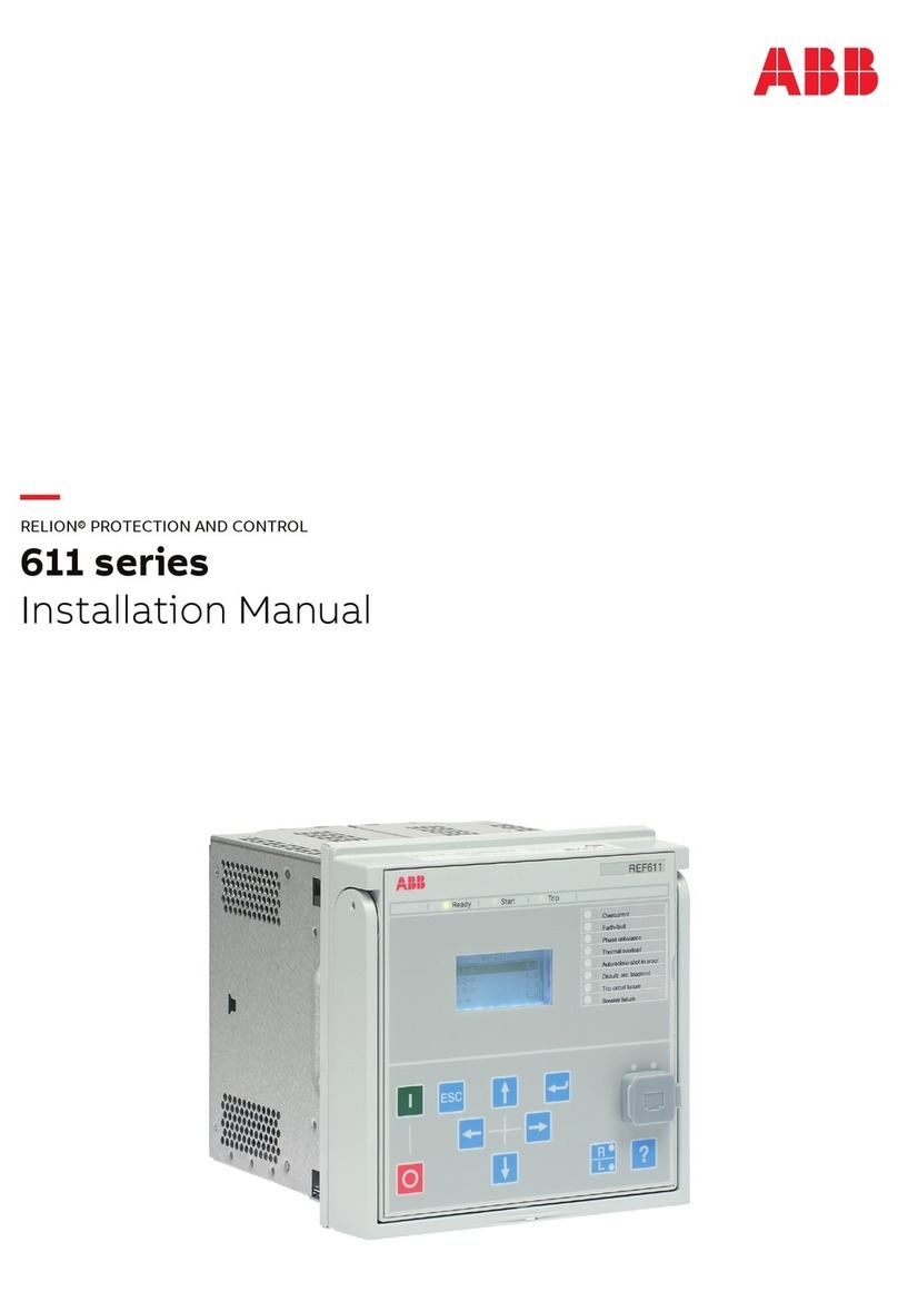
ABB 511 Series User manual

it
lilt
#
\
IPW
IB
7.2
.
1.7
-
1
Issue
C
Instructions
Overcurrent
Relays
CATALOG
SERIES
223
/
423
DRAWOUT
SEMI
-
FLUSH
MOUNTED
SINGLE
PHASE
,
TWO
PHASE
,AND
THREE
-
PHASE
RELAYS
INVERSE
VERY
INVERSE
EXTREMELY
INVERSE
DEFINITE
TIME
.
TYPE
511
TYPE
51
Y
TYPE
51
E
TYPE
51
D
SHORT
TIME
LONG
TIME
LONG
TIME
INVERSE
.
TYPE
51
S
.
.
TYPE
51
L
TYPE
51
IM
LONG
TIME
VERY
INVERSE
....
TYPE
51
YM
gown
-
,
rK
'
$
/
*
a
*
*
BBC
Brow
"
?
a
cuflvi
A i
!
»
SINGLE
PHASE
FOR
RESIDUAL
GROUND
PROTECTION
THREE
PHASE
FOR
PHASE
PROTECTION
Courtesy of NationalSwitchgear.com

IB
-
7.2
.
1.7
-
1
PAGE
2
SOLID
-
STATE
OVERCURRENT
RELAYS
INSTRUCTIONS
FOR
CIRCUIT
-
SHIELD
®
SOLID
-
STATE
RELAYS
DRAWOUT
SEMI
-
FLUSH
MOUNTED
SINGLE
PHASE
,
TWO
PHASE
,
AND
THREE
PHASE
TABLE
OF
CONTENTS
3
.
Be
sure
the
trip
circuit
is
interrupted
by
an
"
a
"
contact
to
remove
high
currents
from
solid
-
state
output
circuits
.
Solid
-
state
output
circuits
have
inherently
high
momentary
current
ratings
and
low
continuous
current
ratings
.
Never
exceed
the
ratings
.
4
.
When
applying
input
current
to
protective
relays
,
be
sure
to
interrupt
the
input
current
immediately
after
the
relay
operates
.
5
.
Load
(
trip
coils
or
auxiliary
relays
)
must
draw
at
least
0.10
amps
to
insure
operation
.
SCR
'
s
require
a
minimum
current
to
remain
conducting
after
triggering
.
Parallel
a
resistance
with
a
low
current
coil
to
guarantee
the
holding
current
,
if
necessary
.
6
.
Do
not
attempt
to
manually
operate
target
vanes
on
CIRCUIT
-
SHIELD
overcurrent
relays
.
Although
the
targets
return
their
indication
under
shock
,
they
can
be
damaged
by
manual
operation
with
a
pencil
or
pointed
object
.
7
.
Do
not
apply
high
voltage
tests
to
solid
-
staie
relays
.
If
a
control
wiring
insulation
test
is
required
,
bond
all
terminals
together
and
disconnect
ground
wire
before
applying
test
voltage
.
8
.
Besuretonotetheconnectionstoterminals
9
,
10
,
and
11
(
described
under
CONNECTIONS
on
page
3
)
required
for
the
proper
operation
of
the
TIME
and
INSTANTANEOUS
elements
.
Jumper
links
are
supplied
with
all
relays
.
9
.
Only
the
lower
circuit
ooard
of
the
CIRCUIT
-
SHIELD
overcurrent
relay
is
removable
.
This
board
should
insert
smoothly
.
Do
not
use
force
.
10
.
Note
that
removal
of
the
tap
block
pin
is
equivalent
to
setting
the
highest
tap
.
11
.
Follow
test
instructions
to
verify
that
the
relay
is
in
proper
working
order
.
CAUTtON
:
Since
troubleshooting
entails
working
with
energized
equipment
,
caution
should
be
taken
to
avoid
personal
shock
.
Only
competent
technicians
familiar
with
good
safety
practices
should
service
these
devices
.
Introduction
Precautions
Placing
Relay
into
Service
Testing
While
in
Service
Application
Data
Calibration
and
Acceptance
Testing
Pg
.
2
Pg
.
2
Pg
.
3
Pg
.
3
Pg
.
4
Pg
18
INTRODUCTION
These
instructions
contain
the
information
required
to
properly
install
,
operate
,
and
test
the
complete
line
of
Type
51
solid
-
state
overcurrent
relays
.
The
CIRCUIT
-
SHIELD
overcurrent
relay
is
housed
in
a
semi
-
flush
drawout
relay
suitable
for
conventional
panel
mounting
.
All
connections
to
the
relay
are
made
at
terminals
located
on
the
rear
of
the
case
and
clearly
numbered
,
one
(
1
)
through
twelve
(
12
)
.
CURRENT
,
TIME
,
and
INST
,
pickup
controls
are
lo
-
cated
on
the
front
panel
behind
a
removable
clear
plastic
cover
.
TIME
and
INST
,
target
indicators
are
also
mounted
on
the
front
panel
.
Both
targets
are
reset
by
means
of
a
pushbutton
extending
through
the
relay
cover
.
PRECAUTIONS
The
following
precautions
should
be
taken
when
applying
solid
-
state
relays
:
1
.
Incorrect
wiring
may
result
in
damage
to
solid
-
state
relays
,
Be
sure
wiring
agrees
with
the
connection
diagram
for
the
particular
relay
before
the
relay
is
energized
.
Be
sure
control
power
is
applied
in
the
correct
polarity
before
applying
control
power
.
2
.
Apply
only
the
rated
control
voltage
marked
on
the
relay
front
panel
.
Unlike
conventional
relay
contacts
,
solid
-
state
outputs
are
rated
for
a
particular
control
voltage
.
If
rectified
AC
voltage
is
used
in
place
of
a
battery
,
proper
filtering
will
be
required
to
insure
SCR
"
Holding
Current
"
.
Courtesy of NationalSwitchgear.com

IB
-
7.2
.
1.7
-
1
PAGE
3
SOLID
-
STATE
OVERCURRENT
RELAYS
PLACING
THE
RELAY
INTO
SERVICE
Time
Dial
One
of
ten
(
10
)
time
-
current
curves
is
selected
by
a
two
-
element
control
labeled
TIME
on
the
left
side
of
the
relay
front
panel
.
a
)
A
ten
position
SWITCH
giving
discrete
steps
1
through
10
.
b
)
A
screwdriver
adjusted
VERNIER
providing
continuous
time
adjustment
between
steps
.
When
the
vernier
,
marked
“
ADJ
”
,
is
turned
to
the
extreme
counterclockwise
position
,
the
time
-
current
curve
shown
on
the
switch
has
been
selected
.
The
vernier
provides
a
continuous
time
adjustment
between
the
switch
selected
curve
and
the
curve
indicated
by
the
next
higher
number
.
Intermediate
positions
can
be
verified
by
test
.
Instantanoous
Instantaneous
pickup
is
selected
by
the
potentiometer
dial
on
the
right
side
of
the
relay
front
panel
.
The
dial
is
labeled
"
INST
.
"
The
markings
indicate
multiples
of
the
pickup
tap
setting
.
1
.
RECEIVING
,
HANDLING
,
STORAGE
Upon
receipt
of
the
CIRCUIT
-
SHIELD
relay
(
when
not
included
as
part
of
a
switchboard
)
examine
for
shipping
damage
.
If
damage
or
loss
is
evident
,
file
a
claim
at
once
and
promptly
notify
the
nearest
Asea
Brown
Boveri
Of
-
fice
.
Use
normal
care
in
handling
to
avoid
mechanical
damage
.
The
CIRCUIT
-
SHIELD
system
has
no
vital
moving
parts
and
if
kept
reasonably
clean
and
dry
,
has
no
practical
limit
to
its
operating
life
.
2
.
INSTALLATION
Mounting
The
outline
dimensions
and
panel
drilling
and
cutout
information
is
given
in
Figure
2
.
Connections
External
connection
diagram
is
shown
in
Figure
1
.
For
the
instantaneous
function
to
be
operable
Terminals
9
and
10
must
be
externally
shorted
.
Instantaneous
relay
operation
can
be
cancelled
for
reclosing
applications
by
using
an
external
supervisory
contact
connected
to
these
terminals
.
For
example
,
if
the
phase
one
(
1
)
tap
is
set
at
six
(
6
)
amperes
and
the
INST
dial
is
set
at
eight
(
8
)
,
the
INST
,
setting
is
:
For
the
TIME
function
to
be
operable
terminals
10
and
11
must
be
externally
shorted
.
The
TIME
function
can
be
cancelled
for
directional
or
voltage
control
by
using
an
external
supervisory
contact
connected
to
these
terminals
.
6
amps
X
8
=
48
amps
Consequently
,
an
instantaneous
trip
will
occur
at
48
amps
in
phase
one
(
1
)
of
the
relay
.
TESTING
IN
SERVICE
In
general
,
it
is
not
necessary
to
schedule
periodic
maintenance
of
this
relay
.
However
,
if
a
trip
test
is
desired
to
confirm
the
proper
functioning
of
the
system
,
the
following
procedure
can
be
used
.
Mounted
in
Switchgear
Tests
should
be
made
on
a
de
-
energized
main
circuit
.
If
tests
are
to
be
made
on
an
energized
circuit
,
be
sure
to
take
all
necessary
precautions
.
It
is
customary
to
test
the
trip
circuit
of
electro
-
mechanical
overcurrent
relays
by
manually
closing
the
trip
contacts
to
trip
their
associated
circuit
breakers
.
If
the
contacts
are
allowed
to
part
before
the
seal
-
in
contact
closes
,
the
relay
contacts
are
eroded
by
the
arc
.
Also
,
high
transient
voltages
will
appear
from
trip
bus
to
positive
.
This
problem
is
avoided
in
the
CIRCUIT
-
SHIELD
overcurrent
relay
by
the
operatic
nal
test
feature
.
Separate
pushbuttons
labeled
"
TRIP
'
'
are
provided
for
the
TIME
and
INST
,
functions
.
The
pushbuttons
,
recessed
to
prevent
accidental
operations
,
will
cause
the
breaker
to
trip
.
All
CIRCUIT
-
SHIELD
relays
have
metal
front
panels
which
are
connected
through
printed
circuit
board
runs
and
connector
wiring
to
a
terminal
at
the
rear
of
the
relay
case
.
The
terminal
is
marked
"
G
"
and
is
located
as
shown
in
Fig
.
2
below
.
In
all
applications
this
terminal
should
be
wired
to
ground
.
Special
care
must
be
taken
to
connect
control
power
in
the
proper
polarity
.
Reversing
plus
(
+
)
and
minus
(
-
)
will
cause
SCR
A
and
SCR
Bto
block
the
flow
of
trip
current
and
the
relay
will
not
function
.
For
capacitor
trip
applications
,
the
plus
{
+
)
output
of
the
capacitor
trip
device
must
be
connected
to
terminal
7
of
the
relay
,
the
negative
(
-
)
to
terminal
8
.
3
.
SETTINGS
Current
Pickup
Taps
A
tap
block
for
each
phase
is
located
on
the
relay
front
panel
.
Each
tap
block
provides
for
seven
(
7
)
pickup
settings
which
are
marked
in
CT
secondary
amperes
.
When
a
pin
is
pulled
out
.
that
phase
switches
to
the
maximum
tap
setting
.
The
pin
may
be
moved
with
the
relay
in
service
.
Courtesy of NationalSwitchgear.com
IB
-
7.2
.
1.7
-
1
PAGE
4
SOLID
-
STATE
OVERCURRENT
RELAYS
A
portion
of
the
control
voltage
is
applied
to
the
time
circuit
when
the
TIME
pushbutton
is
depressed
.
The
time
del
$
y
circuit
then
produces
a
trip
signal
,
in
a
time
corresponding
to
approximately
two
(
2
)
multiples
of
current
tap
setting
,
(
at
nominal
control
voltage
)
,
and
the
TIME
target
operates
.
For
this
test
the
INST
,
pickup
must
be
set
above
(
2
)
multiples
or
the
INST
,
element
will
trip
first
.
Similarly
,
a
portion
of
the
control
voltage
is
applied
to
the
INST
,
circuit
when
the
INST
,
pushbutton
is
depressed
,
producing
a
trip
signal
and
operating
the
INST
,
target
.
On
special
three
phase
relays
with
individual
phase
targets
,
the
tests
described
will
cause
the
middle
phase
target
to
operate
in
addition
to
the
TIME
or
INST
,
target
.
Test
Accessory
A
test
accessory
which
can
be
used
to
quickly
check
the
primary
C
.
T
.
'
s
,
the
upper
non
-
drawout
input
section
of
the
relay
,
control
power
,
and
the
continuity
of
the
trip
circuit
is
available
from
the
factory
.
This
drawout
test
accessory
is
plugged
into
the
relay
in
place
of
the
drawout
element
to
make
the
checks
.
See
IB
-
7.2
.
1.7
-
2
for
details
.
These
overcurrent
relays
are
offered
with
the
follow
-
ing
pickup
ranges
:
Taps
$
Range
0.1
,
0.15
,
0.2
,
0.25
,
0.3
,
0.4
,
0.5
0.1
-
0.5
0.5
,
0.6
,
0.8
,
1.0
,
1.2
,
1.5
,
2.0
0.5
-
2.0
1.5
,
2.0
,
2.5
,
3
,
4
,
5
,
6
1.5
-
6.0
2
,
5
,
2.8
,
3.1
,
3.5
,
4.0
,
4.5
,
5.0
2.5
-
5
2.5
,
3.75
,
5
,
6.3
,
7.5
,
8.6
,
10
2.5
-
10
4
,
5
,
6
,
7
,
8
,
10
,
12
4
-
12
$
When
tap
plug
is
removed
,
affected
phase
reverts
to
the
maximum
pickup
.
TOLERANCES
TIME
PICKUP
TIME
DELAY
dial
#
10
(
2
-
20
multiples
)
dial
#
1
(
2
-
20
multiples
)
±
5
%
of
tap
setting
±
5
%
10
ms
or
±
10
%
(
whichever
is
larger
)
±
10
%
of
pickup
amps
(
tap
x
dial
setting
)
INST
.
PICKUP
RATINGS
APPLICATION
DATA
TEMPERATURE
The
Type
51
series
of
overcurrent
relays
provide
overcurrent
protection
phase
-
to
-
phase
or
phase
-
to
-
ground
.
They
are
designed
to
be
operated
by
standard
five
(
5
)
ampere
secondary
current
transformers
.
The
output
circuit
(
trip
circuit
)
will
operate
conventional
cir
-
cuit
breaker
trip
coils
at
the
DC
voltage
specified
on
the
relay
nameplate
.
These
relays
can
oe
used
for
all
applications
where
conventional
electromechanical
relays
are
used
.
They
come
in
seven
different
time
-
current
curve
families
,
INVERSE
(
511
)
,
VERY
INVERSE
(
51
Y
)
,
EXTREMELY
INVERSE
(
51
E
)
,
SHORT
TIME
(
51
S
)
,
LONG
TIME
(
51
L
)
,
DEFINITE
TIME
(
51
D
)
,
LONG
TIME
INVERSE
(
51
IM
)
,
and
LONG
TIME
VERY
INVERSE
(
51
YM
)
.
A
standard
INSTANTANEOUS
function
or
a
special
INVERSE
INSTANTANEOUS
function
can
be
furnished
as
an
option
with
any
of
the
time
families
.
.
..
25
°
C
ambient
-
15
CC
to
+
55
°
C
-
30
°
C
to
+
70
°
C
Nominal
Additional
±
5
%
tolerance
Must
operate
FREQUENCY
Nominal
Additional
±
5
%
tolerance
60
Hertz
.
+
1
to
-
3
Hertz
INPUT
CIRCUIT
Phase
one
(
1
)
current
—
terminals
1
and
2
.
Phase
two
(
2
)
current
—
terminals
3
and
4
.
Phase
three
(
3
)
current
—
terminals
5
and
6
.
The
current
input
for
single
-
phase
relays
is
made
at
terminals
3
and
4
.
Each
input
current
is
fed
to
a
tapped
transformer
primary
.
The
secondary
winding
produces
a
voltage
across
a
burden
resistor
.
This
voltage
is
rectified
and
supplied
to
the
static
circuitry
.
The
pickup
of
the
static
circuit
is
adjusted
to
the
desired
pickup
current
by
tap
selection
of
the
transformer
primary
turns
.
Any
one
of
seven
control
voltages
can
be
obtained
:
24
Vdc
,
32
Vdc
,
48
Vdc
,
125
Vdc
,
250
Vdc
,
175
Vdc
(
120
Vac
capacitor
trip
)
,
350
Vdc
(
240
Vac
capacitor
trip
)
.
Courtesy of NationalSwitchgear.com
IB
-
7.2
.
1.7
-
1
PAGE
5
SOLID
-
STATE
OVERCURRENT
RELAYS
OUTPUT
CIRCUIT
The
CIRCUIT
-
SHIELD
overcurrent
relay
energizes
the
breaker
trip
coil
by
means
of
an
output
SCR
.
Two
SCR
’
s
are
provided
,
one
for
the
time
delay
and
pne
for
the
instantaneous
circuit
as
indicated
in
the
wiring
diagram
shown
in
Figure
1
.
As
shown
,
relay
terminal
7
is
connected
to
the
control
power
positive
,
with
the
trip
coil
connected
to
relay
terminal
12
through
a
52
/
a
contact
.
SCR
A
is
gated
by
the
time
delay
circuit
,
while
SCR
B
is
gated
by
the
instantaneous
circuit
.
Note
that
once
an
SCR
is
gated
(
turned
on
)
,
it
will
remain
in
conduction
until
its
anode
current
falls
below
its
holding
current
which
typically
is
5
to
20
milliamperes
.
Consequently
,
the
trip
coil
current
must
be
interrupted
with
the
52
/
a
contact
.
INPUT
CURRENT
RATINGS
Input
Current
,
1
0
or
3
0
(
CT
Secondary
Amperes
)
Tap
Range
.
A
Time
0
1
-
0.5
0.5
-
2.0
1.5
-
6.0
2.5
-
5.0
2.5
-
10
300
multiples
of
pickup
tap
setting
or
235
A
rms
.
whichever
is
less
.
1
Second
390
A
rms
4
-
12
Continuous
All
Ranges
1.5
multiples
of
pickup
tap
setting
.
BURDEN
The
burden
of
the
Circuit
Shield
overcurrent
relay
is
very
low
,
allowing
the
use
of
current
transformers
which
would
give
unsatisfactory
performance
if
they
were
driving
electro
-
mechanical
relays
.
Because
the
input
characteristic
of
the
Circuit
Shield
relay
is
nonlinear
,
an
impedance
cannot
be
specified
,
however
,
the
burden
voltage
across
the
relay
current
inputterminals
can
be
readily
calculated
for
any
given
value
of
current
transformer
secondary
current
:
OUTPUT
TRIP
CIRCUIT
RATINGS
Max
.
Current
,
Amps
DC
Range
of
Operation
Nominal
Voltage
6
Cycles
1
Second
Continuous
24
Vdc
32
Vdc
48
Vdc
125
Vdc
250
Vdc
175
Vdc
350
Vdc
18
-
30
24
-
40
28
-
60
70
-
140
140
-
280
100
-
195
200
-
385
1.0
TAP
Roc
+
Is
x
R
V
=
IT
(
AMPS
)
OHMS
30
1
15
V
=
burden
voltage
(
volts
)
Is
=
current
transformer
secondary
current
(
amperes
)
IT
=
relay
pickup
current
tap
setting
(
amperes
)
R
=
D
C
.
resistance
of
relay
input
circuit
(
ohms
)
(
select
from
table
)
0
5
092
0.6
.
078
0
8
065
*
Capacitor
Trip
Applications
1.0
055
048
1 2
TARGET
CIRCUITS
The
target
indicators
for
the
TIME
and
INST
,
circuits
are
polarity
sensitive
devices
which
are
set
by
current
flow
through
the
corresponding
trip
SCR
.
Target
reset
is
accomplished
by
the
control
power
connection
(
terminals
7
and
8
of
Figure
1
)
through
the
TARGET
RESET
pushbutton
.
Standard
relays
have
2
targets
TIME
and
INST
.
Three
phase
relays
may
be
specially
ordered
with
5
targets
—
TIME
,
INST
,
and
PHASE
targets
.
These
3
additional
targets
wil
indicate
which
phase
currents
are
in
excess
of
tap
setting
when
the
relay
trips
the
breaker
.
.
040
1.5
2.0
032
NOTES
:
1.5
.
042
1
.
for
units
with
0.1
to
0.5
A
tap
range
,
the
Is
x
R
term
is
negligible
.
2.0
034
2
,
5
038
2
.
for
units
with
2
to
5
A
tap
range
,
use
values
shown
for
1.5
to
6
A
unit
.
3.0
.
026
4.0
.
022
5.0
020
6.0
.
0185
4
.
020
5
.
020
6
.
0185
7
.
0175
FREQUENCY
RATING
See
page
17
.
8
.
017
10
.
0165
12
.
0165
Courtesy of NationalSwitchgear.com
IB
-
7.2
.
1.7
-
1
PAGE
6
SOLID
-
STATE
OVERCURRENT
RELAYS
Internal
Connection
Diagrams
12
D
223
A
TIME
-
OVERCURRENT
RELAYS
Type
51
(
with
or
without
Instantaneous
)
Single
Phase
Relays
—
omit
coils
1
-
2
and
5
-
6
)
(
Two
Phase
Relays
—
omit
coil
3
-
4
)
°
~
Vo
4
*
3
?
V
?
rV
?
7
I
TEST
11
L
.
10
L
.
9
o
o
u
£
E
1
0 8
O
’
TIME
12
30
£
LIT
-
10
o
'
*
J
>
TEST
(
-
)
(
)
I
T
TARGET
Vw
'
l
TT
«
U
»
towm
Ce
*
wc
«
»
<
•
»
UMdl
1
MST
.
Not
*
:
User
to
remove
links
Ly
or
L
|
only
if
torque
-
control
contacts
are
to
be
used
:
1
.
Remove
only
Lx
for
torque
-
control
of
51
.
(
Time
element
)
2
.
Remove
only
L
|
for
torque
control
of
50
.
(
Instantaneous
element
)
$
2
*
3
in
Three
-
phase
and
ground
with
instantaneous
52
—
i
1
i
-
i
i
i
i
i
6
5
4
3
2
1
12
M
10
9
0
7
1
u
O
O
*
o
o
6
5
4
3
2
FIGURE
1
Internal
Connections
and
Typical
External
Connection
Diagram
i
I
2
H
I
0
9
0
HB
*
—
O
TRIPPING
BUS
RELIABLE
O
.
C
.
SUPPLY
52
5
«
Courtesy of NationalSwitchgear.com

IB
-
7.2
.
1.7
-
1
PAGE
7
SOLID
-
STATE
OVERCURRENT
RELAYS
I
l
I
TIME
-
CURRENT
CHARACTERISTICS
6
.
1
.
09
U
5
.
08
.
07
-
4
CIRCUIT
©
SHIELD
®
.
06
3
.
05
Type
50
§
8
.
04
§
-
2
fc
S
03
1
AJ
.
02
1
»
.
01
o
o
ooooo
*
3
*
LT
3
CD
h
>
QOO
)
0
o
Tf
LO
CO
r
»
oocno
o
o
LO
co
r
^
ooo
»
*
—
co
CM
o
ro
CM
CM
MULTIPLES
OF
INST
.
SETTING
(
TAP
X
INST
.
DIAL
)
TYPE
50
INSTANTANEOUS
Oct
.
19
,
1971
TCC
605807
6
5
4
3
3
C
2
1
TYPE
501
INVERSE
INSTANTANEOUS
Aug
29
,
1972
TCC
605812
Courtesy of NationalSwitchgear.com
SOLID
-
STATE
OVERCURRENT
RELAYS
IB
-
7.2
.
1.7
-
1
PAGE
13
90
80
70
TIME
-
CURRENT
CHARACTERISTICS
60
50
40
30
1800
©
20
10
600
9
8
6
5
300
4
3
2
o
X
00
O
o
60
2
.
9
O
X
o
.
8
00
LU
.
7
OJ
00
2
.
6
o
>
.
5
LU
30
o
5
.
4
h
-
.
3
.
2
.
1
6
.
09
-
5
.
08
.
07
.
06
-
4
.
05
^
3
.
04
-
2
.
03
.
02
-
1
.
01
CM
in
co
r
-
coo
o
co
oo o
o
oo
oo
o
in
co
rs
oo
o o
in
co
r
-
»
coo
«
—
o
CM
CO
o
CM
CURRENT
IN
MULTIPLES
OF
SETTING
TYPE
51
IM
LONG
TIME
,
INVERSE
TCC
605813
MAR
.
26
,
1974
Courtesy of NationalSwitchgear.com

IB
-
7.2
.
1.7
-
1
PAGE
17
SOLID
-
STATE
OVERCURRENT
RELAYS
6.230
208.53
r
CIRCUIT
-
SHIELD
|
OVERCURRENT
RELAY
•
lil
*
i
*
7
t
3
1.167
30
.
lt
6.362
164.66
k
—
PANCL
.
300
|
T
127
?
Q
An
rVj
rVn
«
16
«
6
1
»
4
«
>
3
o
2
»
|
<
18
<
>
12
>
7
j
I
4.675
<
23.83
3
—
t
T
rj
H
IG
IF
IE
ID
1
C
8
AlFLEXlTEST
«
0
/
006666
6
/
6
/
6
/
SWITCH
I
/
o
“
o
6 6
<
T
~
6
/ /
/
I
^
yfp
I
29
A
5
I
4
G
0
I
2
tf
37
61.81
I
FT
-
I
LI
o
I
FtOMT
VICW
(
4
HOLU
tioc
view
TRIP
BUS
A
1
52
1
B
o
T
6
n
5
n
4
n
3
n
2
n l
fC
3
>
687
93.68
52
0
00
0
0
0
MMCL
CO
TOOT
f
A
T
T
0
0 0
0
0
0
it
ii
IO
"
"
T
i
1.644
“
V
3
h
3
^
Suggested
arrangement
for
drawout
type
test
facilities
to
be
used
by
those
wishing
to
maintain
their
conventional
test
procedures
when
checking
solid
-
state
overcurrent
relays
.
®
0
*
0
L
^
87
J
1
I
-
1
8
TU
0
NUMWC
88
(
RACK
view
)
60.88
4.623
<
46.28
This
sketch
shows
Westinghouse
’
s
Flexitest
Switch
.
However
,
G
.
E
.
,
States
,
Meter
Devices
,
or
other
types
can
be
used
.
Fig
.
3
—
Typical
Test
Switch
Connections
OMHCNSION
3
ARC
-
JjSP
Fig
.
2
—
Overcurrent
Relay
Outline
and
Drilling
Use
the
following
conversion
table
to
convert
60
Hz
curves
to
50
Hz
operation
.
This
conversion
applies
only
to
relays
rated
50
/
60
Hz
.
FREQUENCY
RATING
Type
51
series
relays
with
a
nameplate
rating
of
50
/
60
Hz
are
suitable
for
operation
at
either
frequency
;
how
-
ever
,
the
time
current
curves
shown
on
pages
7
-
16
apply
only
to
60
Hz
operation
.
To
determine
the
operat
-
ing
time
for
50
Hz
applications
use
the
correction
factors
shown
here
.
60
HZ
MULTIPLE
50
HZ
MULTIPLE
11
2
2
3
3.18
4
4.38
Type
511
inverse
relays
with
a
nameplate
rating
of
50
Hz
(
only
)
will
perform
per
curve
TCC
605801
when
op
-
erated
at
50
Hz
.
The
correction
factors
should
NOT
be
used
.
5
5.58
6
6.78
8
9.18
10
11.58
17.58
23.58
48.42
15
20
40
Plot
the
time
corresponding
to
a
multiple
of
current
in
the
60
Hz
column
against
the
multiple
in
the
50
Hz
column
.
EXAMPLE
:
Find
the
time
corresponding
to
4
multiples
of
current
on
the
60
Hz
curve
in
the
instruction
book
.
Plot
this
value
of
time
for
4.38
multiples
of
current
for
50
Hz
.
Courtesy of NationalSwitchgear.com

IB
-
7.2
.
1.7
-
1
PAGE
18
SOLID
-
STATE
OVERCURRENT
RELAYS
Replacement
of
Terget
Head
Assembly
The
relay
target
is
an
electrically
operated
,
magneti
-
cally
held
device
.
Should
the
orange
/
black
target
disk
be
damaged
,
it
can
easily
be
replaced
.
Order
target
head
assembly
part
609283
-
102
from
the
factory
.
Replacement
procedure
:
1
.
From
the
front
of
the
relay
,
pull
the
existing
plastic
holder
straight
off
using
needle
nose
pliers
.
2
.
Carefully
place
the
new
target
assembly
on
the
pole
pieces
with
disk
end
closest
to
you
.
3
.
With
control
power
applied
,
press
the
target
reset
button
.
If
the
target
shows
orange
,
remove
the
as
-
sembly
,
rotate
180
degrees
,
and
reinstall
.
Actuate
target
reset
.
Target
should
turn
to
black
.
TESTING
1
.
MAINTENANCE
AND
RENEWAL
PARTS
CAUTION
:
Since
troubleshooting
entails
working
with
energized
equipment
,
caution
should
be
taken
to
avoid
personal
shock
.
Only
competent
technicians
familiar
with
good
safety
practices
should
service
these
de
-
vices
.
No
routine
maintenance
is
required
on
these
relays
.
Follow
test
instructions
to
verify
that
the
relay
is
in
proper
working
order
.
We
recommend
that
an
inopera
-
tive
relay
be
returned
to
the
factory
for
repair
;
however
,
a
circuit
description
and
/
or
a
schematic
diagram
are
available
for
those
who
wish
to
attempt
repairs
.
Contact
your
local
sales
engineer
or
contact
the
factory
.
These
relays
have
an
SCR
(
thyristor
)
as
the
output
stage
.
This
output
SCR
may
be
ordered
from
the
factory
(
part
no
.
605211
-
006
)
.
Replacement
target
head
assembly
may
be
ordered
should
the
target
be
mechanically
dam
-
aged
.
Also
available
from
the
factory
are
circuit
card
ex
-
tenders
.
All
these
relays
use
the
10
point
extender
,
catalog
200
X
0010
.
2
.
HIGH
POTENTIAL
TESTS
Do
not
apply
high
voltage
tests
to
solid
-
state
relay
circuits
.
If
a
control
wiring
insulation
test
is
required
,
bond
all
terminals
together
and
disconnect
grounding
wire
before
applying
test
voltage
.
Drawout
Element
Lower
drawout
circuit
boards
of
the
same
catalog
number
are
interchangeable
.
The
board
is
removed
by
using
the
metal
pull
knobs
on
its
front
panel
.
Removing
the
board
will
not
cause
an
open
C
.
T
.
secondary
or
a
false
trip
,
therefore
,
the
board
may
be
changed
while
the
relay
is
in
service
.
Note
that
the
relay
is
identified
by
a
serial
number
on
the
underside
of
the
circuit
board
.
The
relay
time
-
current
characteristic
and
control
voltage
rating
is
determined
by
the
drawout
element
.
This
nameplate
data
will
be
found
on
the
front
panel
of
the
drawout
element
.
3
.
ACCEPTANCE
TESTS
Follow
calibration
test
procedure
under
paragraph
4
.
Check
the
following
points
:
time
dial
1
,
current
5
-
times
pickup
;
time
dial
10
,
current
10
times
pickup
;
time
dial
10
,
current
5
times
pickup
.
Operating
times
should
be
within
±
5
%
of
the
times
shown
on
the
time
-
current
characteristic
curve
.
Courtesy of NationalSwitchgear.com
IB
-
7.2
.
1.7
-
1
PAGE
19
SOLID
-
STATE
OVERCURRENT
RELAYS
4
.
CALIBRATION
TESTS
(
Also
see
Appendix
A
)
Connect
the
CIRCUIT
-
SHIELD
relay
to
the
test
source
,
proper
DC
control
voltage
(
to
match
relay
)
,
and
synchronous
timer
as
shown
in
Figure
4
.
Also
,
set
pickup
tap
to
desired
value
.
TIME
—
Pickup
1
)
Set
TIME
dial
to
required
value
.
2
)
With
DC
source
off
,
preset
test
current
to
95
%
of
pickup
value
.
3
)
With
DC
on
,
apply
test
current
.
No
trip
should
occur
.
4
)
With
DC
off
,
preset
test
current
to
105
%
of
pickup
value
.
5
)
With
DC
on
,
apply
testcurrent
.
The
relay
should
trip
and
operate
the
TIME
target
.
(
Allow
sufficient
time
)
6
)
Reset
target
by
pressing
the
RESET
pushbutton
.
TIME
—
Delay
Curve
1
)
Set
INST
,
dial
to
maximum
position
(
20
X
)
.
2
)
Set
TIME
dial
to
required
value
,
per
time
-
current
curves
.
3
)
With
DC
off
,
preset
test
current
to
300
%
of
pickup
value
.
4
)
With
DC
on
,
apply
test
current
.
The
relay
should
trip
in
a
time
within
the
tolerances
shown
on
page
4
.
5
)
Reset
target
by
pressing
the
RESET
pushbutton
.
INST
.
—
Pickup
1
)
Set
INST
,
dial
to
required
value
.
2
)
With
DC
off
,
preset
current
to
90
%
of
required
value
(
TAP
X
INST
.
DIAL
)
.
3
)
With
DC
on
,
apply
testcurrent
.
Relay
should
nottrip
on
INST
.
(
i
.
e
.
no
INST
,
target
indication
)
.
4
)
With
DC
off
,
preset
test
current
to
110
%
of
required
value
.
5
)
With
DC
on
,
apply
test
current
.
Relay
should
trip
giving
INST
,
target
.
6
)
Reset
target
by
pressing
the
RESET
pushbutton
.
R
=
RELAY
C
=
CLUTCH
M
=
MOTOR
DC
ON
/
OFF
SW
.
CIRCUIT
-
SHIELD
SW
I
ol
ARW
ol
<
7
^
0
lo
b
NOTE
:
If
a
rectifier
is
to
be
used
as
the
DC
source
for
testing
,
the
filter
capacitor
should
be
at
least
250
ufd
.
2
o
r
~
O
0
yRS
/
°
R
A
$
DC
SWJ
?
9
AiO
SOURCE
4
*
2
TIMER
AC
I
5
o
oil
~
)
I
20
VAC
JTEST
SOURCE
6
o
I
2
"
IP
•
NOTE
:
FOR
3
-
PHASE
RELAYS
,
PHASES
A
&
C
CAN
BE
SIMILARLY
TESTED
BY
ALTERNATELY
CONNECTING
THE
TEST
SOURCE
T
01
—
2
and
5
—
6
.
+
rAR
[
AITI
I
b
-
Ll
0
|
i
®
i
|
®
(
p
(
M
?
II
5
II
59
O
-
T R
i
-
R
I
20
DC
AUX
.
RELAY
TYPE
HEA
6
I
OR
EOUIV
.
VAC
I
AC
2
NOTE
:
Auxiliary
relays
with
coil
resistances
greater
than
10
ohms
/
volt
must
have
a
parallel
resistor
added
across
the
relay
coil
.
Size
resistor
to
draw
100
ma
current
from
DC
source
Fig
.
4
—
Calibration
Test
Circuit
Courtesy of NationalSwitchgear.com
IB
-
7.2
.
1.7
-
1
PAGE
20
SOLID
-
STATE
OVERCURRENT
RELAYS
APPENDIX
A
Note
that
the
test
current
wave
distortion
is
more
apparent
at
the
low
current
tap
setting
(
highest
relay
burden
)
and
at
high
current
multiples
(
lowest
test
source
impedances
)
.
CIRCUIT
-
SHIELD
solid
-
state
overcurrent
relays
have
been
designed
with
a
low
burden
characteristic
.
This
relay
burden
is
such
that
the
primary
current
transformer
will
not
saturate
at
high
fault
current
values
if
theCT
is
selected
so
that
its
saturation
point
is
above
one
multiple
of
the
relay
pickup
setting
.
This
is
accomplished
by
a
specially
designed
input
transformer
in
the
relay
which
saturates
at
just
above
pickup
current
.
In
addition
to
improving
the
accuracy
performance
of
the
primary
current
transformer
,
this
feature
also
effectively
prevents
internal
solid
-
state
components
from
being
subjected
,
to
high
currents
and
voltages
under
fault
conditions
.
CIRCUIT
-
SHIELD
TEST
TABLES
NOTE
:
You
need
not
use
these
tables
if
you
desire
to
make
the
standard
receiving
calibration
check
described
under
calibration
testing
.
When
testing
protective
relays
with
test
sources
of
limited
capacity
the
accuracy
of
test
results
is
affected
by
the
wave
shape
of
the
test
current
.
Where
extremely
accurate
calibration
test
are
desired
,
the
attached
test
Tables
prepared
under
laboratory
conditions
with
standard
CIRCUIT
-
SHIELD
relays
can
be
used
:
Table
1
—
Resistance
Testing
(
“
STATES
”
resistance
bank
#
33560
.
R
)
Table
2
—
Reactance
Testing
(
“
G
.
E
.
”
reactor
,
#
6054975
)
Table
3
—
MULTI
-
AMP
Unit
(
SR
-
51
test
set
)
CONSULT
FACTORY
FOR
TEST
CURRENT
CORRECTIONS
TO
BE
USED
FOR
TEST
SETS
NOT
LISTED
IN
THIS
APPENDIX
.
TABLE
1
CIRCUIT
-
SHIELD
OVERCURRENT
RELAY
TEST
CURRENT
CORRECTION
—
RESISTANCE
TESTING
120
VOLT
SOURCE
(
FIXED
)
(
STATES
#
33560
R
)
4
-
12
AMP
-
TAP
RANG
2
TEST
CURRENT
MULT
.
0.5
-
2
AMP
IANGE
-
9
1.5
-
6
AMP
RANGE
TAP
\
6
TAP
8
10
12
1.0
1.2
1.5
2.0
2.5
3
4
5
7
0.5
0.6
0.8
5.00
6.00
7.00
8.00
10.00
12.00
1.00
1.50
2.00
2.50
3
.
PC
4
.
PC
0.50
0.6
C
0.80
1.20
PICKUP
10.00
12.00
14.00
16.00
24.00
1.22 1.62
2.02
2.42
3.02
4.02
5.02
6.02
8.02
20.00
1.02
2
X
36.10
15.10
18.10
21.10
24.10
30.10
4.55
7.55
9.0
E
12.1
C
1.86
2.46
3.06
3.65
6.05
1.56
3
X
48.10
32.11
10
,
10
12.1
C
16.10
20.10
24.10
28.10
40.10
2.51
3.31
iUll
4.91
6.11
8
^
11
2
^
12
4
X
40.20
60.18
-
10.29
12.70
15.2
C
20.2
C
25.20
30.20
35.20
50.20
3.15
4.19
5.19
6.19
7.68
2.70
5
X
18.3
C
24.30
30.30
36.30
42.30 48.30
15.30
3.85
5.09
6.28
12.30
3.30
7.48
9.28
6
X
32.5
C
40.50
48.50
56.50
12.50
16.50
20.50
24.5
C
5.36
6.94
8.53
10.10
4
,
57
8
X
25.80
30.8
C
40.81
50.80
8.88
10.90
12.90
15.80
20.80
5.95
6.92
IPX
24.50
39.40
46.9
C
11.3
C
14.201
17.10
20.00
31.90
9.94
15
X
53.50
23.90
27.80
33.70
43.60
20.10
14.90
16.5
C
20
X
This
table
lists
corrected
test
currents
for
one
(
1
)
to
twenty
(
20
)
multiples
of
each
tap
setting
available
on
CIRCUIT
-
SHIELD
relays
.
These
test
currents
cause
the
relay
to
produce
the
trip
time
corresponding
to
current
transformer
(
CT
)
operation
,
as
will
be
encountered
in
actual
service
Courtesy of NationalSwitchgear.com
This manual suits for next models
7
Other ABB Relay manuals

ABB
ABB CAP 501 Guide

ABB
ABB Relion 615 series User manual

ABB
ABB SSV-T Manual

ABB
ABB RELION Series Installation and operation manual

ABB
ABB RED670 Relion 670 series Quick start guide

ABB
ABB RELION REF615R User manual

ABB
ABB E 200 DU User manual

ABB
ABB HU Manual

ABB
ABB CM-ESS.1 User manual

ABB
ABB REJ 521 User manual