ABB SPAU 331 C Parts list manual

U
aux
Ser.No.
80...265 V
18...80 V
2
5
~
–
U1 U2 U3
–
fn=
50Hz
60Hz (
U
)
SPAU 331 C
0076B
n
U
/
=(
U
)
100V 110V
n
U
/
=100V 110V
0
RS 613
SGR
01
1
2
3
4
5
6
7
8
0000
SPCU 1C6
1
2
3
4
5
n
)(
U
o
>
/
>
tt
%
[]
>>
/
tt
%
[]
/
n
UU
o
%
[]
>>
n
)(
U
o
0000
SPCU 3C15
1
2
3
4
5
6
7
8
/
<
tt
%
[]
n
)(
U
<
/
n
UU
min
/
n
UU
<
/
n
UU
max
n
)(
U
<<
3
/
tt
%
[]
<<
/
n
UU
<<
3
0000
2
n
U
>
U
o
[ ]
%
[ ]
s
>
t
0.05 1.0
>>
n
U
U
o
[ ]
%
[ ]
s
>>
t
RESET
STEP
U
o
IRF
U
20
STEP
SG1
1
2
3
4
5
6
7
8
10
∞
01
0.5
1.0
o
UU
o
>>
>
SPCU 1C6
0008A
0.05
0.5
50
10
80
n
U
U<
0.1 1.0
n
U
RESET
STEP
IRF
STEP
SG1
1
2
3
4
5
6
7
8
01
0.5
1.0
SPCU 3C15
0.1
0.5
0.4 1.2
0.8
U12 U23 U31
U<
3U<<
k<
3U
<<
1.2
0.1
0.6
U
<<
U<
[ ]
s
<
t
[ ]
s>
t
0412A
0061A
SPC 000
SPAU 331 C
Voltage relay
User´s manual and Technical description

2
1MRS 750123-MUM EN
Issued 96-12-02
Version A (replaces 34 SPAU 12 EN1)
Checked TK
Approved TK
Data subject to change without notice
SPAU 331 C
Voltage relay
Contents Features .......................................................................................................................... 3
Application .....................................................................................................................3
Description of operation ................................................................................................. 4
Connections ................................................................................................................... 5
Operation indicators and push-buttons .......................................................................... 8
Signal flow diagram and configuration switches.............................................................. 9
Power supply module.................................................................................................... 11
Output relay module .................................................................................................... 12
Technical data ............................................................................................................... 13
Maintenance and repair ................................................................................................ 16
Spare parts .................................................................................................................... 16
Delivery alternatives ..................................................................................................... 16
Dimension drawings and mounting.............................................................................. 17
Order numbers and ordering information .................................................................... 18
The complete manual for the voltage relay SPAU 331 C includes the following submanuals:
Voltage relay SPAU 331 C, general description........................ 1MRS 750123-MUM EN
Residual overvoltage relay module SPCU 1C6 ........................ 1MRS 750509-MUM EN
Undervoltage relay module SPCU 3C15 ................................. 1MRS 750588-MUM EN
General characteristics of C type relay modules ....................... 1MRS 750328-MUM EN

3
Features Two-stage residual overvoltage relay module
containing a low-set residual overvoltage stage
U0> and a high-set residual overvoltage stage
U0>>
Both residual overvoltage stages feature definite
time characteristic and wide setting ranges
Two-stage undervoltage relay module containing
a higher under voltage stage U< and a lower
undervoltage stage 3U<<
The three-phase undervoltage stage U< starts if
one or more of the phase-to-phase voltages fall
below the set start level
The three-phase under voltage stage 3U<< starts
if all three phase-to-phase voltages fall below the
set start level
The under voltage stage U< can be given defi-
nite time characteristic or inverse time charac-
teristic while the under voltage stage 3U<< fea-
tures definite time characteristic only
Numerical display of setting values, currently
measured values, fault values, operate times,
event messages etc.
Serial interface for connection of the relay to
the serial bus and a substation level communi-
cation and reporting system and/or a remote
control system
High system reliability and availability through
integrated self-supervision system with auto-
diagnostics capabilities in the relay modules
The voltage relay SPAU 331 C is intended for
the supervision of the bus bar voltages of distri-
bution substations, both the residual voltage and
the phase-to-phase voltages. The complete volt-
age relay contains two protection relay modules.
The residual voltage is measured with a residual
overvoltage relay module type SPAU 1C6 in-
cluding two operation stages. The phase-to-
phase voltage is measured with an undervoltage
relay module type SPCU 3C15.
The voltage relay SPAU 331 C is a member of
the SPACOM product family and as such it is
provided with a serial communication port.
Over the serial communication port and an
optional bus connection module of the SPA-
ZC_ series the relay can be connected to the
optical fibre SPA bus and further to a substa-
tion level data communication and reporting
system and/or a remote control system.
Application

4
Description of
operation
When the residual voltage of the monitored
network exceeds the set start level of the low-set
residual overvoltage stage U0> the relay mod-
ule SPCU 1C6 starts. If the fault persists the
U0> stage trips after the set operate time t> has
elapsed. Correspondingly, the high-set residual
overvoltage stage U0>> starts when its set start
level is exceeded and trips when its set operate
time t>> has elapsed.
When one of the phase-to-phase voltages of the
monitored network falls below the set start level
of the undervoltage stage U<, the relay module
SPCU 3C15 starts. If the undervoltage situa-
tion persists the U< stage trips after the set (at
definite time mode) or calculated (at inverse
time mode) operate time t< has elapsed. Corre-
spondingly, the under voltage stage 3U<< starts
when all three phase-to-phase voltages simulta-
neously fall below the set start level and trips
when its set operate time t<< has elapsed.
The operation of the undervoltage stage U< can
be given inverse time characteristic or definite
time characteristic. At inverse time characteris-
tic the operate time is a function of the meas-
ured voltage and the set time multplier k and
the operate time is shorter the lower the meas-
ured voltage. The undervoltage stage 3U<< fea-
tures definite time characteristic only.
By turning switch SG1/5 on the front panel of
the undervoltage relay module SPCU 3C15 in
position 1, the operation of the undervoltage
stage U< can be blocked, when at least one of
the measured phase-to-phase voltages falls be-
low 0.2 x Un. Further, the operation of the un-
dervoltage stage U< can be blocked by the start
signal of the undervoltage stage 3U<<, switch
SG1/8 in position 1.
Tripping of both operation stages of the under-
voltage relay module and the residual voltage
relay module can be blocked by means of an
external control signal applied to the control
input 10-11 of the relay. The operation stages
to be blocked are selected with switches 4 and 5
of switch group SGB in the relay modules re-
spectively, see section "Signal flow diagram".
Fig. 1. Operation diagram for the undervoltage relay module SPCU 3C15 when selector switch
SG1/5 = 1, i.e. starting of the undervoltage stage is blocked at voltage levels under 0.2 x Un.
U</UnSet start level of the undervoltage stage U<
SS1 Start signal of the undervoltage stage U<
TS1 Trip signal of the undervoltage stage U<

5
Connections
Fig. 2. Connection diagram for the voltage relay SPAU 331 C.
Uaux Auxiliary supply voltage
A, B…F Output relays
IRF Self-supervision alarm
SGR Switchgroup for programming of starting and tripping signals
U1 Residual overvoltage relay module SPCU 1 C6
U2 Undervoltage relay module SPCU 3C15
U3 Unoccupied module place
U4 Output relay module SPTR 6B3
U5 Power supply module SPGU 240A1 or SPGU 48B2
U6 Energizing input module SPTE 4B9
SPA-ZC_ Bus connection module
Rx/Tx Optical fibre receiver (Rx) and transmitter (Tx) of the bus connection module

6
Fig. 3. Rear wiew of the voltage relay SPAU 331 C.

7
Specification of input and output terminals
Terminal Function
number
13-14 Phase-to-phase voltage U12 (100 V)
13-15 Phase-to-phase voltage U12 (110V)
16-17 Phase-to-phase voltage U23 (100 V)
16-18 Phase-to-phase voltage U23 (110 V)
19-20 Phase-to-phase voltage U31 (100 V)
19-21 Phase-to-phase voltage U31 (110 V)
28-29 Residual voltage U0(100 V)
28-30 Residual voltage U0(110V)
10-11 External blocking signal BS1
61-62 Auxiliary supply voltage. The positive pole (+) of the DC supply is connected to
terminal 61. The auxiliary supply voltage range is marked on the system front plate
of the relay.
63 Protection earth (PE)
65-66 Tripping output relay A (heavy-duty) for all stages, U0>, U0>>, U< and 3U<<
67-68-69 Alarm signal output relay B for stages stages U0>>, U< and 3U<<
73-74-75 Alarm and start signal output relay C for stage U<
76-77-78 Alarm and start signal output relay D for stage 3U<<
79-80-81 Alarm signal output relay E for stage U0>
70-71 -72 Self-supervision output relay F. In normal service conditions the contact gap 70-72
is closed. In a fault situation the contact gap 71-72 closes.
NOTE!
Detailed information about the programming of starting and tripping signals in
switchgroups SGB and SGR is given in the section "Signal flow diagram and
conficuration switches".
The voltage relay SPAU 331 C can be connected
to the optical fibre SPA data bus by means of a
9-pole D type connector located on the rear
panel of the voltage relay, and a matching bus
connection module type SPA-ZC_. The opto-
connectors of the optical fibres are blugged into
the counter connectors Rx and Tx of the bus
connection module and the optical fibres are
linked from one protection relay to another and
to the control data communicator.

8
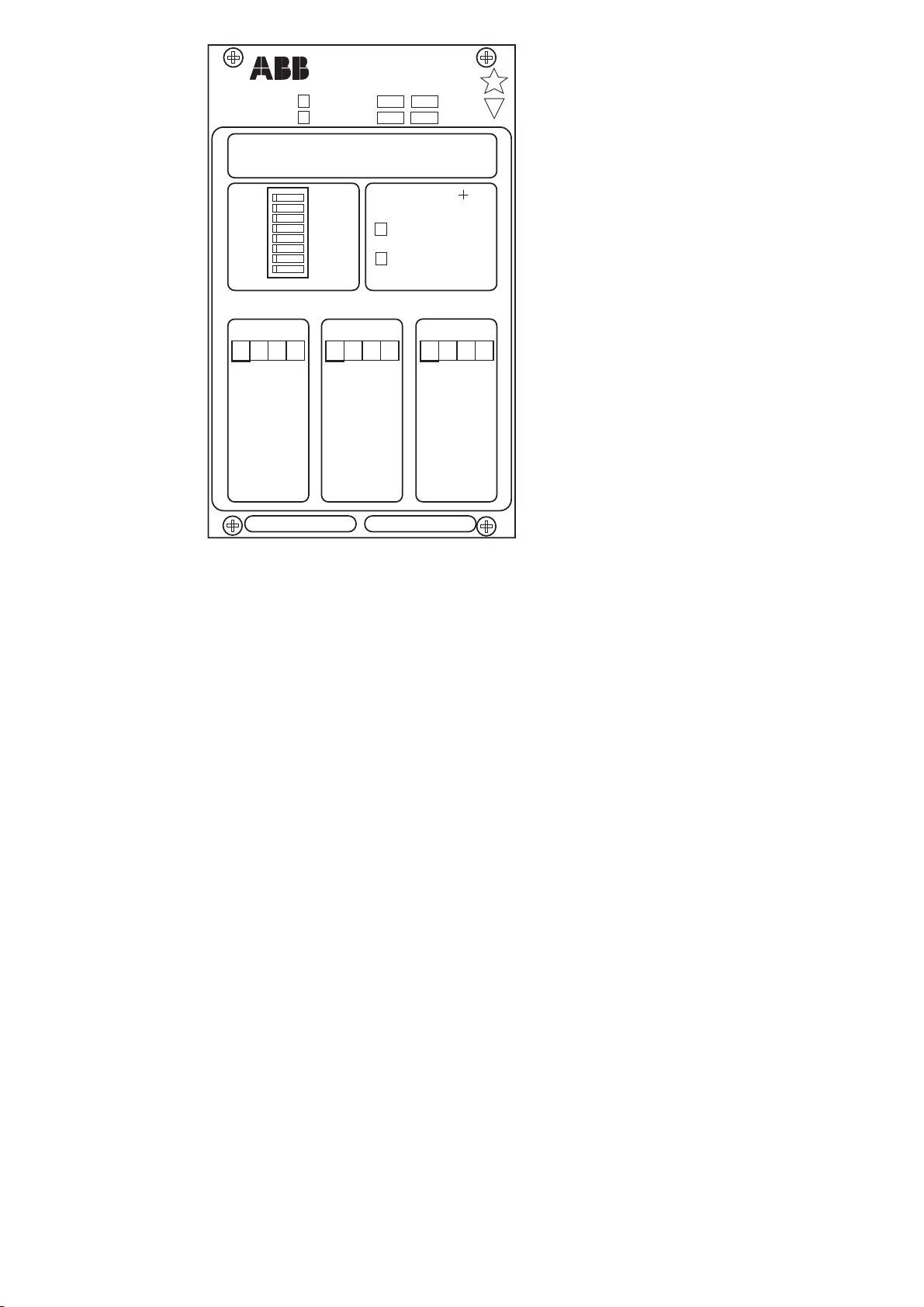
Fig. 4. System front panel of the voltage relay
SPAU 331 C.
1. The green LED Uaux on the system panel is
lit when the power supply of the relay is op-
erating.
2. The relay modules are provided with two
operating stages and each stage has its own
yellow/red LED operation indicator. The op-
eration indicator goes on with a yellow light
when the operation stage starts and with a
red light if the stage delivers a tripping signal
as well. The LED indicators can be given self-
reset or manual reset mode of operation. Nor-
mally, when the stage resets, the red opera-
tion indicator remains lit after being switched
on to indicate by whitch stage the tripping
was initiated.
3. The front panels of both relay modules are
provided with a numerical display for indi-
cation of measured and set values, two push-
buttons marked STEP and RESET, a pro-
gramming switchgroup SG1 for selection of
relay functions and four setting knobs for op-
eration values. The STEP push-button can
be used for scanning through the measured
and set values of the module and for presen-
tation of the values concerned on the display
of the module. The RESET push-button is
used for resetting locally the red operation
indicators for tripping. An unreset operation
indicator does not affect the operation of the
relay module and thus, the module is
constantely operative.
4. The front panels of the relay modules are pro-
vided with a red LED used as a self-supervi-
sion alarm indicator IRF which indicates that
the self-supervision system has detected a per-
manent fault in the protection relay. Further,
the relay modules are provided with separate
LED indicators on the front panel for indi-
cation of the measured residual and phase-
to-phase voltages.
5. The cover of the protection relay case is made
of transparent, UV-stabilized polycarbonate
polymer and provided with three push-but-
tons for scanning of the relay parameters by
means of the separate displays of the mod-
ules and the STEP push-buttons inside the
cover. To enable resetting of the modules by
means of the RESET push-buttons, the cover
of the relay case must be opened using the
locking screws for the case.
Detailed operation instructions are given in the
manuals describing the individual relay mod-
ules and in the document "General characteris-
tics of C-type relay modules".
Operation
indicators and
push-buttons
U
aux
Ser.No.
80...265 V
18...80 V
2
5
~
–
U1 U2 U3
–
fn=
50Hz
60Hz (
U
)
SPAU 331 C
0076B
n
U
/
=(
U
)
100V 110V
n
U
/
=100V 110V
0
RS 613
SGR
01
1
2
3
4
5
6
7
8
0000
SPCU 1C6
1
2
3
4
5
n
)(
U
o
>
/
>
tt
%
[]
>>
/
tt
%
[]
/
n
UU
o
%
[]
>>
n
)(
U
o
0000
SPCU 3C15
1
2
3
4
5
6
7
8
/
<
tt
%
[]
n
)(
U
<
/
n
UU
min
/
n
UU
<
/
n
UU
max
n
)(
U
<<
3
/
tt
%
[]
<<
/
n
UU
<<
3
0000

9
Signal flow
diagram and
configuration
switches
In certain applications it may be necessary to
alter the factory settings of the configuration
switches of the relay SPAU 331 C. Fig. 5 illus-
trates schematically how the starting, tripping,
control and blocking signals can be routed in-
side the relay to obtain the protection functions
required by the intended application.
Fig. 5. Control signal routes between the relay modules of the voltage relay SPAU 331 C.
BS1
Uo
234 567 81
Uo> Uo>>
t> t>>
TS1 TS2
23456781
t<
SS1 SS2
TS1 TS2
U<
k<
3U<<
t<<
SGB
SGB
SPCU 1C6 (U1)
SPCU 3C15 (U2)
SPC 000 (U3)
SGR
1
2
3
4
5
6
7
8
B
C
D
E
A
U
12,
U
23,
U
31

10
Configuration
switches
Part of the starting and tripping signals from
the relay modules are permanently connected
to the output relays, whereas part of the output
signals are routed through switchgroup SGR.
The switchgroup is located at the front edge of
the output relay module. The switches are set
through the opening in the relay system front
panel.
The switchgroups SGB on the PC-boards of the
relay modules SPCU 1C6 and SPCU 3C15 are
used for routing incoming external blocking sig-
nals to the protection stages to be blocked.
The functions of the switchgroups SGB and
SGR are described in the tables as follows:
Switchgroup SGR on relay system panel
Switch Function Factory
setting
SGR/1 Tripping signal from stage U< to output relay A 1
SGR/2 Tripping signal from stage 3U<< to output relay A 1
SGR/3 Tripping signal from stage U0> to output relay A 1
SGR/4 Tripping signal from stage U0>> to output relay A 1
SGR/5 Tripping signal from stage U< to output relay B 1
SGR/6 Tripping signal from stage 3U<< to output relay B 1
SGR/7 Starting signal from stage U< to output relay C 1
SGR/8 Starting signal from stage 3U<< to output relay D 1
Switchgroup SGB on PC-board in residual overvoltage relay module SPCU 1C6
Switch Function Factory
setting
SGB/1 Not in use 0
SGB/2 Not in use 0
SGB/3 Not in use 0
SGB/4 Blocking signal BS1 for blocking of U0>-tripping 0
SGB/5 Blocking signal BS1 for blocking of U0>>-tripping 0
SGB/6 Not in use 0
SGB/7 Not in use 0
SGB/8 Not in use 0
Switchgroup SGB on PC-board in undervoltage relay module SPCU 3C15
Switch Function Factory
setting
SGB/1 Not in use 0
SGB/2 Not in use 0
SGB/3 Not in use 0
SGB/4 Blocking signal BS1 for blocking of U<-tripping 0
SGB/5 Blocking signal BS1 for blocking of 3U<<-tripping 0
SGB/6 Not in use 0
SGB/7 Not in use 0
SGB/8 Not in use 0

11
Power supply
module
The power supply module is located behind the
system front panel of the relay together with
the output relay module. The supply module is
a separate relay module and can be withdrawn
after removal of the system front panel. The
power supply module produces the voltages re-
quired by the relay modules from the auxiliary
supply voltage.
There are two types of power supply modules,
differing only in input voltage:
SPGU 240 A1:
Nominal voltage Un= 110/120/230/240 V ac
Un= 110/125/220 V dc
Operative range U = 80...265 V ac/dc
SPGU 48 B2:
Nominal voltage Un= 24/48/60 V dc
Operative range U = 18...80 V dc
The power supply type is marked on the system
front panel.
The power supply module is a transformer con-
nected, i.e. galvanically separated primary and
secondary circuits, flyback type rectifier. The
primary circuit is protected by a fuse F1, 1A
(slow) in SPGU 240 A1 and 4A (fast) in SPGU
48 B2, which are located on the printed circuit
board of the module.
When the power supply is on, a green LED in-
dicator Uaux is lit on the system panel. The su-
pervision of the supply voltages for the electron-
ics is located on the regulating modules. The
self-supervision alarm is given if any of the sec-
ondary voltages differ more than 25% from the
nominal value. Also, if the power supply mod-
ule is missing, or if there is no auxiliary supply
to the voltage regulator at all, an alarm is given.

12
Output relay
module
The output relay module SPTR 6B3 is located
behind the system front panel of the relay to-
gether with the power supply module. The out-
put relay module forms its own withdrawable
relay module after removal of the system front
plate. The module contains all output relays,
A...F, the control circuits of the relays as well as
the electronic circuitry of the external control
inputs.
Fig. 6. Block diagram for the output relay module SPTR 6B3.
TS1/U1 Tripping signal of U0>-stage
TS2/U1 Tripping signal of U0>>-stage
SS1/U2 Starting signal of U>-stage
TS1/U2 Tripping signal of U>-stage
SS2/U2 Starting signal of U<-stage
TS2/U2 Tripping signal of U<-stage
BS1 External blocking input signal to U<-stage
A Tripping output relay A (heavy-duty) for all stages, U0>, U0>>, U> and U<
B Alarm signal output relay B for stages U0>>, U> and U<
C Alarm signal output relay C for stage U>
D Alarm signal output relay D for stage U<
E Alarm signal output relay E for stage U0>
F Self-supervision output relay F
IRF Self-supervision input signal
SGR Switchgroup for programming of starting and tripping signals
ENA Enable output signal from control circuits
The input and output signals of the output re-
lay module are related to the fixed positions of
the relay modules which cannot be changed in
the relay housing. The output signals from each
relay module and PC-board location are wired
individually to the output relay module. It must
be pointed out that the relay modules have to
be plugged into the relay case as illustrated in
the figure on the front page in order to secure
that the connection diagram drawn for the re-
lay assembly also would correspond to the physi-
cal function of the protective device.

13
Technical data Energizing inputs
Rated voltage Un100 V 110 V
Terminal numbers
- phase-to-phase voltage U12 13-14 13-15
- phase-to-phase voltage U23 16-17 16-18
- phase-to-phase voltage U31 19-20 19-21
- residual voltage U028-29 28-30
Continuous voltage withstand 2 x Un
Burden at rated voltage Un<0.5 VA
Rated frequency fn, according to order 50 Hz or 60 Hz
External control inputs
Terminal numbers 10-11
External control voltage 18...265 V dc or 80...265 V ac
Current drain, typically 2...15 mA
Contact outputs
Tripping outputs
Terminal numbers
- trip relay A 65-66
Rated voltage 250 V dc/ac
Continuous current carrying capacity 5 A
Make and carry for 0.5 s 30 A
Make and carry for 3 s 15 A
Breaking capacity for dc when the control circuit
time constant L/R ≤40 ms at 48/110/220 V dc 5A /3A /1 A
Contact material AgCdO2
Signalling outputs
Terminal numbers
- alarm relay B 67-68-69
- alarm relay C 73-74-75
- alarm relay D 76-77-78
- alarm relay E 79-80-81
- self-supervision relay F 70-71-72
Rated voltage 250 V dc/ac
Continuous current carrying capacity 5 A
Make and carry for 0.5 s 10 A
Make and carry for 3 s 8 A
Breaking capacity for dc when the control circuit
time constant L/R ≤40 ms at 48/110/220 V dc 1A /0.25A /0.25A
Contact material AgCdO2
Auxiliary power supply
Voltage range of power supply modules:
SPGU 240 A1
- Nominal voltage Un110/120/230/240 V ac
110/125/220 V dc
- Operative range 80...265 V ac/dc
SPGU 48 B2
- Nominal voltage Un24/48/60 V dc
- Operative range 18...80 V dc
Power consumption under quiescent/
operation conditions 10 W / 15 W

14
Residual overvoltage relay module SPCU 1C6
See "Technical data" in the document 1MRS 750509-MUM EN for the relay module.
Two-stage undervoltage relay module SPCU 3C15
See "Technical data" in the document 1MRS 750588-MUM EN for the relay module.
Data communication
Transmission mode Fibre-optic serial bus
Coding ASCII
Data transfer rate, selectable 300, 1200, 2400, 4800 or 9600 Bd
Optical bus connection module powered from
the host relay
- for plastic-core cables SPA-ZC 21 BB
- for glass-fibre cables SPA-ZC 21 MM
Optical bus connection module powered from
the host relay or from an external power source
- for plastic-core cables SPA-ZC 17 BB
- for glass-fibre cables SPA-ZC 17 MM
Test voltages *)
Dielectric test voltage according to IEC 255-5 2 kV, 50 Hz, 1 min
Impulse test voltage according to IEC 255-5 5 kV, 1.2/50 µs, 0.5 J
Insulation resistance according to IEC 255-5 >100 MΩ, 500 V dc
Disturbance tests *)
High-frequency (1 Mhz) disturbance test
according to IEC 255-22-1
- common mode 2.5 kV
- differential mode 1.0 kV
Electrostatic discharge test according
to IEC 255-22-2 and IEC 801-2, class III
- air discharge 8 kV
- contact discharge 6 kV
Fast transients according to IEC 255-22-4,
class III and IEC 801-4, level IV
- power supply inputs 4 kV, 5/50 ns
- other inputs 2 kV, 5/50 ns
Rf electromagnetic field test according to
IEC 1000-4-3 and ENV 50140, f = 80...1000 Mhz 10 V/m
Conducted rf disturbance test according to
ENV 50141 and IEC 1000-4-6, f = 150 kHz...80 Mhz 10 V

15
Emission tests
Radiated and conducted emission according
to EN 55011 Class A
EMC tests
CE approved and tested according to
EN 50081-2 and EN 50082-2
Environmental conditions
Service temperature range -10...+55°C
Temperature dependence <0.2%/°C
Transport and storage temperature range
according to IEC 68-2-8 -40...+70°C
Damp heat test according to IEC 68-2-30 ≤95%, 55°C, 6 cycles
Degree of protection by enclosure of flush mounting
relay case according to IEC 529 IP54
Weight of fully equipped relay 5.5 kg
*) The insulation and disturbance tests do not apply to the serial port, which is used for the bus
connection module only.

16
Maintenance
and repair
When the voltage relay SPAU 331 C is operat-
ing under the conditions specified in "Techni-
cal data", the relay requires practically no main-
tenance. The voltage relay includes no parts or
components that are sensitive to physical or elec-
trical wear under normal operating conditions.
Should the temperature and humidity at the
operating site differ from the values specified,
or the atmosphere contain chemically active
gases or dust, the relay should be visually in-
spected in association with the secondary test-
ing of the relay. This visual inspection should
focus on:
- Signs of mechanical damage to relay case and
terminals
- Collection of dust inside the relay case; remove
with compressed air
- Signs of corrosion on terminals, case or inside
the relay
If the relay malfunctions or the operating val-
ues differ from those specified, the relay should
be overhauled. Minor measures can be taken by
the customer but any major repair involving the
electronics has to be carried out by the manu-
facturer. Please contact the manufacturer or his
nearest representative for further information
about checking, overhaul and recalibration of
the relay.
The protection relay contains circuits sensitive
to electrostatic discharge. If you have to with-
draw a relay module, ensure that you are at the
same potential as the module, for instance, by
touching the case.
Note!
Protective relays are measuring instruments and
should be handled with care and protected
against moisture and mechanical stress, espe-
cially during transport.
Spare parts Residual overvoltage relay module SPCU 1C6
Two-stage undervoltage relay module SPCU 3C15
Power supply modules
- Uaux = 80...265 V ac/dc (operative range) SPGU 240 A1
- Uaux = 18...80 V dc (operative range) SPGU 48 B2
Output relay module SPTR 6B3
Interface module SPTE 4B9
Case (including connection module) SPTK 4B9
Bus connection module SPA-ZC 17_ or SPA-ZC 21_
Delivery
alternatives Type Equipment SPCU SPCU
1C6 3C15
SPAU 331 C1 Basic version, residual voltage and undervoltage module x x
SPAU 331 C3 Basic version, residual voltage module alone x
SPAU 331 C5 Basic version, undervoltage module alone x
Delivery versions of the voltage relay SPAU 331 C.

17
Dimension
drawings
and mounting
The basic model of the protection relay case is
designed for flush-mounting. When required,
the mounting depth of the case can be reduced
by using raising frames: type SPA-ZX 301 re-
duces the depth by 40 mm, type SPA-ZX 302
by 80 mm and type SPA-ZX 303 by 120 mm.
When projecting mounting is preferred a relay
case type SPA-ZX 306 is used. The relay case
for projecting mounting is provided with front
connectors.
Raising frame
SPA-ZX 301
SPA-ZX 302
SPA-ZX 303
219
179
139
74
114
154
ab
226
162
136
229
293
259
30 34
ab
Panel cut-out
214 ±1
139 ±1
Fig. 6. Dimension and mounting drawings for overvoltage, undervoltage and residual voltage
relay SPAU 331 C.
The relay case is made of profile aluminium and
finished in beige.
The rubber gasket fitted to the mounting collar
provides an IP54 degree of protection by enclo-
sure between the relay case and the mounting
base.
The hinged cover of the case is made of trans-
parent, UV-stabilized polycarbonate polymer
and provided with two sealable locking screws.
The rubber gasket of the cover provides an IP54
degree of protection between the case and the
cover.
The required input and output connections are
made to the multi-pole terminal blocks on the
rear panel. Each screw terminal is dimensioned
for one or two wires of maximum 2.5 mm2. A
connection diagram adjacent to the terminal
blocks illustrates the connection of the termi-
nals.
The 9-pole D-type connector is intended for
serial communication of the relay. A 25-pole D-
type connector is used for connecting the dis-
turbance recorder module via the RS 232 C port
on the front panel to an output device.
The bus connection modules (SPA-ZC 17_ or
SPA-ZC 21_) and fibre-optic cables recom-
mended by the manufacturer should always be
used for the serial communication.

18
Order numbers
and ordering
information
Voltage relay
SPAU 331 C1 RS 613 031 - AA, CA, DA, FA
SPAU 331 C3 RS 613 033 - AA, CA, DA, FA
SPAU 331 C5 RS 613 035 - AA, CA, DA, FA
The letter combinations of the order number denote the rated frequency fnand
the operative range of the auxiliary supply voltage:
AA: fn= 50 Hz, Uaux = 80...265 V ac/dc
CA: fn= 50 Hz, Uaux = 18...80 V dc
DA: fn= 60 Hz, Uaux = 80...265 V ac/dc
FA: fn= 60 Hz, Uaux = 18...80 V dc
Ordering example:
1. Number and type designation 5 pcs SPAU 331 C1
2. Order number RS 613 031 - AA
3. Rated frequency fn= 50 Hz
4. Auxiliary voltage Uaux = 110 V dc
5. Accessories 5 raising frames SPA-ZX 301
5 bus connection modules SPA-ZC 17 MM2A
6. Special requirements –

19

1MRS 750123-MUM EN
ABB Oy
Substation Automation
P.O.Box 699
FIN-65101 VAASA
Finland
Tel. +358 (0)10 22 11
Fax.+358 (0)10 22 41094
www.abb.com/substationautomation
Table of contents
Other ABB Relay manuals

ABB
ABB SPAU 140 C Parts list manual

ABB
ABB REJ 521 User manual

ABB
ABB RXPDK 21H User instructions

ABB
ABB CL Series Instructions for use

ABB
ABB Relion REG670 Instructions for use

ABB
ABB EF19 User manual

ABB
ABB REJ 525 User manual

ABB
ABB RXHL 401 User manual

ABB
ABB REB650 User manual

ABB
ABB Tmax PR222DS/P User instructions