manuals.online logo
Brands
  1. Home
  2. •
  3. Brands
  4. •
  5. ABB
  6. •
  7. Relay
  8. •
  9. ABB KD-10 Manual

ABB KD-10 Manual

Effective: April 1981
NEW
INFORMATION
ABE Power T&D Company Inc.
Relay Division
Coral Springs, FL 33065
Instruction Leaflet
I.L. 41-498.5
Type KD Compensator
Distance Relays Calibration
and Maintenance Procedures
These instructions are intended to supplement
Instruction Leaflets 41-491, 41-498.11, 41-491.4,
41-498.12 and 41-490, covering the KD-1, 4, 41,
5, 10, and 11 line of compensator distance relays,
respectively. These instructions expand on the in-
formation given in these
I.L.'s
and suggest what
elements should be included in a calibration and
maintenance program.
A calibration and maintenance program
should involve two steps: 1) a receiving accept-
ance check and 2) a routine (periodic) mainten-
ance program. These two steps are outlined below:
RECEIVING ACCEPTANCE
Received relays should be subjected to the
checks outlined in the applicable I.L. These checks
will insure that there is no shipping damage and
that the relay has been received in the same cali-
brated condition as it left the factory. They will
insure that set-up procedures such as removing
contact blocking has been accomplished. A re-
ceiving acceptance check should include the
following steps:
1. Perform all of the mechanical and electrical
tests listed in the receiving acceptance section
of the applicable I.L., include the maximum
torque angle test, even if it is not called for
in some
I.L.‘s.
2.
Follow the
appropriate test procedures outlined in
I.L.‘s
covering the K-DAR FIELD TEST UNIT.
It is suggested that all dial test readings in each test
be recorded for future reference. This information
3.
will be very helpful in recognizing possible drift of
electrical characteristics.
If the settings to be applied to the relay when it is
installed are known, the relay should be set to
these settings and checked with the field test units
as noted in step 2 above. A record
for future refer-
ence should be taken.
The relay test values using
the KDAR test unit should check to be within
2
7
percent of the relay settings.
ROUTINE MAINTENANCE
The relay should be checked periodically at
time intervals dictated by previous experience
and practices.Westinghouse recommends that
the time interval between checks be a maximum
of two years. Routine maintenance should include
at
1.
2.
3.
leas; the following steps:
Repeat step 2 or 3 under
Receiving Acceptance
and record test results.
Compare test results with previous results. If
any test values deviate from previous checks
by more than
&5
percent, recheck relay per-
formance in line with the receiving acceptance
checks outlined above step 1.
Retain records of test results on each particular
relay. During each routine maintenance, the
records should be analyzed to determine if
there is any evidence of drift; i.e., continued
change in characteristic in the same direction.
Evidence of drift should be traced to the parti-
cular element involved, usually a capacitor or
resistor and this element replaced.
All possible contingencies which may arise during installation, operation or maintenance, and
all
details
and variations of this equipment do not purport to be covered by these instructions.
ff
further information
is desired by purchaser regarding this
particular
installation, operation or maintenance of this equipment,
the local ABB Power T&D Company Inc. representative should be contacted.
Printed
in U.S.A
4. Some of the more common component pro-
blems may be detected as follows:
With the relay mounted on a panel and energ-
ized by station C.
T.‘s
&
P.
T.‘s,
open all
trip circuits and all current switch positions
12, 13, 14, 16, 17, 18, 19, and, phase C voltage
switches (terminal 9) and if applicable an
additional switch position on the
separately-
energized
38
unit. Check the internal schematic
for your particular relay. Jumper terminal 7
to terminal 9 and to any other applicable switch
normally connected to phase C, on the relay
side (upper half of the switch). The contacts
of both operating units should stay open. If
the
3-phase
unit contact closes, it indicates
misadjustment -of resistor, R3A, or potentio-
meter,
P3A
(most
common cause), or a de-
fective capacitor,
C3C,
follow the instructions
for troubleshooting in Section E for KD-4 and
KD-5 relays and the proper instruction leaflet
for KD, KD-1, and KD-10 and KD-11 relays.
If phase-to-phase unit closes, recheck for:
KD
&
KD-1 relays
RMA
&
RMC-Calibration
KD-4, KD-5,
&
KD-41 relay RAC-Calibration
KD-10
&
KD-11 XLAC-Adjustment
CALIBRATION AND TROUBLE
SHOOTING HINTS:
A. Experience has shown that calibration of the
relay for maximum torque angle is the pro-
cedure most
suscetible
to error. Two poten-
tial sources of error are most common:
1. Instrumentation errors
-
Be sure of the
accuracy of calibration of all instruments
and phase shifters used. Instruments should
be chosen and ranges selected so that
readings are taken with the instrument
reading in the top third of the scale.
When a phase shifter is used, attention
should be paid to the fact that voltage
and current settings will change as the
angle is varied. To avoid inaccuracies due
to this effect, check the voltage and current
settings when contact operation indicates
that maximum torque angle check point
has been reached.
2. Failure or miscalibration of components not
connected with angle adjustment to distin-
guish between the two sources of error it is re-
commended to perform compensator nulling
test as follows:
B. For
KD-4,
41, 5, 10, and 11 relays
Phase-to-phase unit (TAB and TBC
compensators) Maximum Sensitivity Angle
1.
2.
3.
4.
5.
Use “PH-PH-1-2 Phase Test”
-
connec-
tion for TAB-compensator, and
“PH-PH-
2-3” Test connection for TBC compen-
sator. Refer to the figure in the I.L. titled
“Test Connections.”
Measure voltage across
C2A
for TAB and
across
C2C
for TBC.
Set current equal to:
VlF2F
RELAY SETTING
The current should be high enough to pro-
vide an accurate phase angle meter reading,
or any convenient value if a phase-shifter
is used for direct angle reading.
Set the phase shifter for the desired maxi-
mum torque angle value.
Note the voltage.
Vary the phase angle in both directions of
the set value, to see that a low voltage
(below 1 volt) is obtained at the maximum
torque angle setting. If within +2 degrees,
it can be left undisturbed. If the minimum
voltage is obtained at some other angle,
readjust phase shifting resistor or potentio-
meter at the desired angle.
C. For KD and KD-1 Relays
Follow procedure above except:
1. For Ta compensator, use connection
#2
omit voltage connection to terminal 9, dis-
connect LA-lead, insert voltmeter to mea-
sure open circuit voltage and use twice
the current value obtained for KD-10 tests.
Follow procedure outlined above except
adjust
R2A
when required. _
I.L. 41498.5
D.
E.
2.
3.
For
TR
compensator, use procedure out-
lined above, except use
#3
connection and
adjust
R2R
when required.
For
TC
compensator, use connection
#4,
omit voltage connection to terminal 7,
disconnect LC-lead, and adjust
R2C
when
required as per Part I.
Three-phase unit (T compensator) of all KD
type relays:
1.
2.
3.
4.
5.
Use connection
#l.
Measure
VOltage
across
C3A
Set the current equal to:
V1F2F
1.5 Relay Setting
The current should be high enough to pro-
vide an accurate phase angle meter reading,
or any convenient value if a phase-shifter
is used for direct angle reading.
Set the phase-shifter for the desired maxi-
mum torque angle value.
Note the voltage.
Vary phase angle in both directions of the
set value, to see that a low voltage (below
1 volt) is obtained at the maximum torque
angle setting. If minimum voltage is with-
in
+2
degrees, do not readjust. If the mini-
mum voltage is obtained at some other angle
readjust phase-shifting resistor or potentio-
meter at the desired angle.
Suggested Procedure for Detecting and
Replacing Defective
C3C
Capacitor
For KD-4, KD-5 and KD-10 Relays
Step 1
Set S =1 for the 3-phase unit.
Apply approximately 120 volts to relay terminal 7
and 8 and short out terminals 7 and 9 (for
KD-5
between terminals 6 and 9 and some short reach
KD-4).
If contacts of the 3-phase unit close, then, the
C3C
capacitor is under suspicion but im-
properly adjusted
R3A
can be suspected, as
well.
Step 2
Remove the connections made in Step 1.
Apply approximately 120 volts (i.e., 100-130
volts) to: terminals 8 and 9 =
Vg9.
Measure the voltage across the
C3C
capacitor
with a high impedance voltmeter
-
5000
OHMS/volt.
For
.75-20
OHM reach
KD-4
relays, the
minimum_
.voltage
should be Vmin = 3.72 x
Vg9.
If Vmin less than 3.72 x
Vg9
replace
capacitor
C3C.
For .24.35 OHM reach
KD4
and KD-5
relays, the minimum voltage should be Vmin
= 2.82 x
Vg9
if Vmin less than 2.82 x
Vg9,
replace capacitor
C3C.
For all ranges KD-10
use same procedure as for
.75-20
OHM reach.
Step 3
Relays which fail either step 1, or have
C3C
capacitor replaced after failing step 2, or
after
C3A
capacitor iS replaced, require
readjustment of
R3A
or
P3A.
Repeat step 1 and
adjust
R3A
or
P3A
so that
contacts
jUSt
open.
Measure total
R3F
and
R3A
resistance
Omit this procedure for
KD-
10 relays.
a) for
.75-20
OHM reach
KD-4
relays
l when the relay is preheated as per I.L.,
decrease
R3A
setting by 10% of total
R3F and R3A resistance.
or l for a cold rela
R3A
so that t
h
repeat step 1 and adjust
e contact just opens. No
further adjustment is required.
b) for
.2-4.35
OHM reach KD-4 relays with
sub “A” in the style number
l for a cold relay, decrease
R3A
setting
8% of total R3A + R3F resistance.
l for a hot relay, decrease
R3A
setting
8% of total R3A + R3F resistance.
3
c) for
.2-4.35
OHM relays without sub “A”
in style number
l for a cold relay, decreases
R3A
setting
7% of total
R3A
+
R31z
resistance.
l for a hot relay, decrease
R3A
setting
4% of total
R3A
+
R~F
reSiStanCe.
NOTE:
R3A
range of adjustment may occasion-
ally be insufficient. If so, set
R~F
for
maximum resistance, or replace
R~F
resistor with higher value.
d) For KD-10 follow instruction leaflet to
ad-
jUSt
R~A
OI-
P3A.
F)
G.
Suggested procedure for
C3C
for KD-1, KD-41,
KD-11 relays.
4
b)
No voltage test is required across the
C3C
capacitor.
If
C3C
has been found bad (shorted or
leaky) repeat
P3A
or
R3A
adjustment
above.
Suggested Procedure for Replacement of
CzC,
C~A
Capacitors
After the capacitors have been replaced:
a>
b)
Open relay switch 9 (phase C potential).
short terminals 7
&
9 on relay side and apply
approximately 120 volts to terminals 7 and
8.
c)
4
e)
adjust RCA resistor for KD-4-41 relays
and
XIAC
for KD-10-11 relays so contact
just floats
-
favoring contact opening
direction.
if desired, repeat 2.5 volts calibration point.
for KD
&
KD-1 relays, follow procedure
for RMA
&
RMC calibration.
ABB
Network Partner
ABB Power T&D Company Inc.
4300 Coral Ridge Drive
Coral Springs Florida 33065
(954) 752-6700
FAX:
(954)
3455329
-
Printed
in
USA

Other manuals for KD-10

2

This manual suits for next models

5

Other ABB Relay manuals

ABB Relion 615 series User manual

ABB

ABB Relion 615 series User manual

ABB COQ Manual

ABB

ABB COQ Manual

ABB Relion 615 series User manual

ABB

ABB Relion 615 series User manual

ABB REL 356 User manual

ABB

ABB REL 356 User manual

ABB RELION 650 SERIES User manual

ABB

ABB RELION 650 SERIES User manual

ABB MG-6 Manual

ABB

ABB MG-6 Manual

ABB CL-LSR Series Manual

ABB

ABB CL-LSR Series Manual

ABB SPACOM 300 User manual

ABB

ABB SPACOM 300 User manual

ABB PMA Manual

ABB

ABB PMA Manual

ABB C6701 User manual

ABB

ABB C6701 User manual

ABB SSR32 User manual

ABB

ABB SSR32 User manual

ABB Relion 615 series User manual

ABB

ABB Relion 615 series User manual

ABB Relion REG670 Instructions for use

ABB

ABB Relion REG670 Instructions for use

ABB RED615 ANSI User manual

ABB

ABB RED615 ANSI User manual

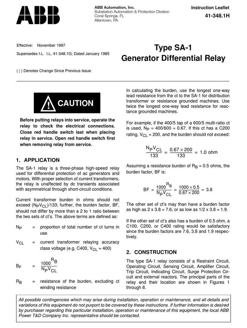
ABB 41-661.2A Manual

ABB

ABB 41-661.2A Manual

ABB CA-26 Manual

ABB

ABB CA-26 Manual

ABB Relion 620 Series User manual

ABB

ABB Relion 620 Series User manual

ABB SPAM 150 C Manual

ABB

ABB SPAM 150 C Manual

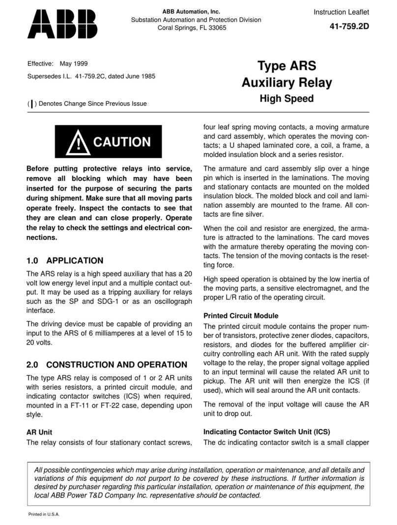
ABB ARS Series Manual

ABB

ABB ARS Series Manual

ABB SPAJ 111 C User manual

ABB

ABB SPAJ 111 C User manual

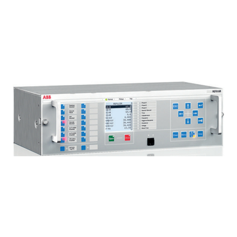
ABB RELION REF615R Installation and operation manual

ABB

ABB RELION REF615R Installation and operation manual

ABB Relion 615 series User manual

ABB

ABB Relion 615 series User manual

ABB HU Manual

ABB

ABB HU Manual

ABB CV-21 Manual

ABB

ABB CV-21 Manual

Popular Relay manuals by other brands

Guard master Minotaur MSR7R manual

Guard master

Guard master Minotaur MSR7R manual

pizzato CS AR-01 Series operating instructions

pizzato

pizzato CS AR-01 Series operating instructions

Eaton ESR5-NOS-31-230VAC manual

Eaton

Eaton ESR5-NOS-31-230VAC manual

Ormazabal ekor.rps General instructions

Ormazabal

Ormazabal ekor.rps General instructions

Pilz PZE X4VP operating manual

Pilz

Pilz PZE X4VP operating manual

Eaton EASY Series Instruction leaflet

Eaton

Eaton EASY Series Instruction leaflet

Zubr D25t Installation and Operation Manua

Zubr

Zubr D25t Installation and Operation Manua

Broyce Control P9625 instructions

Broyce Control

Broyce Control P9625 instructions

Elko elko quick start guide

Elko

Elko elko quick start guide

SMA MFR01-10 installation manual

SMA

SMA MFR01-10 installation manual

KAEL VARko-106-TFT manual

KAEL

KAEL VARko-106-TFT manual

Omron K8AB-TH product manual

Omron

Omron K8AB-TH product manual

Omron K8AB-PM Series manual

Omron

Omron K8AB-PM Series manual

Sulzer CA 462 installation guide

Sulzer

Sulzer CA 462 installation guide

GE IRT51E instructions

GE

GE IRT51E instructions

GE b30 Communications guide

GE

GE b30 Communications guide

Omron G3PE Series manual

Omron

Omron G3PE Series manual

Adam Equipment AE 402 manual

Adam Equipment

Adam Equipment AE 402 manual

manuals.online logo
manuals.online logoBrands
  • About & Mission
  • Contact us
  • Privacy Policy
  • Terms and Conditions

Copyright 2025 Manuals.Online. All Rights Reserved.