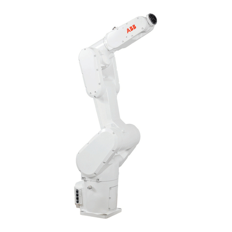
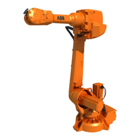
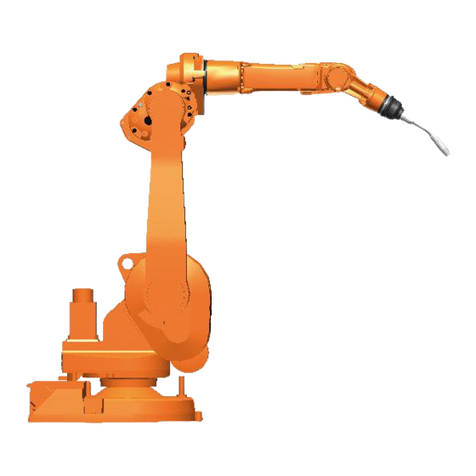
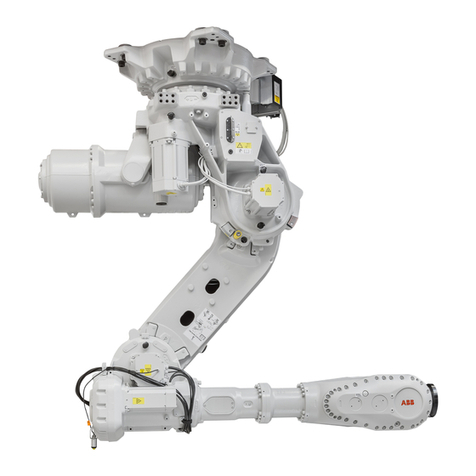
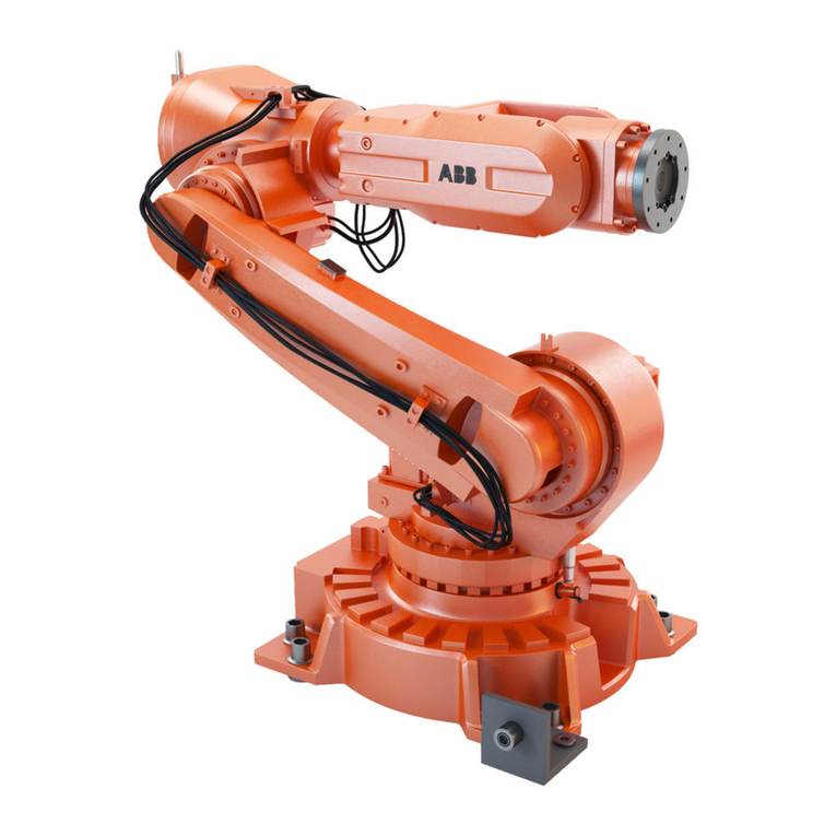
ABB IRB 4400/45 Owner's manual

Product specification
Articulated robot
IRB 4400/45
IRB 4400/60
IRB 4400/L30
IRB 4400/L10
IRB 4450/S
M2004


Product specification
Articulated robot
3HAC9117-1
Rev.N
IRB 4400/45
IRB 4400/60
IRB 4400/L30
IRB 4400/L10
IRB 4450/S
M2004

The information in this manual issubject to change without notice and shouldnotbe construed
as a commitment by ABB. ABB assumes no responsibility for any errors that may appear in
this manual.
Exceptas may beexpresslystatedanywhere in this manual,nothing herein shall be construed
as any kind of guarantee or warranty by ABB for losses, damages to persons or property, fit-
ness for a specific purpose or the like.
In no event shall ABB be liable for incidental or consequential damages arising from use of
this manual and products described herein.
This manual and parts thereof must not be reproduced or copied without ABB's written per-
mission, and contents thereof must not be imparted to a third party nor be used for any unau-
thorized purpose. Contravention will be prosecuted.
Additional copies of this manual may be obtained from ABB at its then current charge.
©Copyright 2004 ABB All right reserved.
ABB AB
Robotics Products
SE-721 68 Västerås
Sweden

Table of Contents
3HAC9117-1 Rev.N 3
Overview 5
1 Description 7
1.1 Structure. . . . . . . . . . . . . . . . . . . . . . . . . . . . . . . . . . . . . . . . . . . . . . . . . . . . . . . . . . . . . . . . . . . . . . . . .7
1.1.1 Introduction . . . . . . . . . . . . . . . . . . . . . . . . . . . . . . . . . . . . . . . . . . . . . . . . . . . . . . . . . . . . . . . .7
1.1.2 Different robot versions . . . . . . . . . . . . . . . . . . . . . . . . . . . . . . . . . . . . . . . . . . . . . . . . . . . . . . .9
1.1.3 Definition of version designation. . . . . . . . . . . . . . . . . . . . . . . . . . . . . . . . . . . . . . . . . . . . . . . .9
1.2 Safety/Standards . . . . . . . . . . . . . . . . . . . . . . . . . . . . . . . . . . . . . . . . . . . . . . . . . . . . . . . . . . . . . . . . .16
1.2.1 Standards . . . . . . . . . . . . . . . . . . . . . . . . . . . . . . . . . . . . . . . . . . . . . . . . . . . . . . . . . . . . . . . . .16
1.2.2 Safety . . . . . . . . . . . . . . . . . . . . . . . . . . . . . . . . . . . . . . . . . . . . . . . . . . . . . . . . . . . . . . . . . . . .17
1.3 Installation . . . . . . . . . . . . . . . . . . . . . . . . . . . . . . . . . . . . . . . . . . . . . . . . . . . . . . . . . . . . . . . . . . . . . .19
1.3.1 Introduction . . . . . . . . . . . . . . . . . . . . . . . . . . . . . . . . . . . . . . . . . . . . . . . . . . . . . . . . . . . . . . .19
1.3.2 Operating requirements . . . . . . . . . . . . . . . . . . . . . . . . . . . . . . . . . . . . . . . . . . . . . . . . . . . . . .20
1.3.3 Mounting the manipulator . . . . . . . . . . . . . . . . . . . . . . . . . . . . . . . . . . . . . . . . . . . . . . . . . . . .21
1.4 Calibration and References . . . . . . . . . . . . . . . . . . . . . . . . . . . . . . . . . . . . . . . . . . . . . . . . . . . . . . . .25
1.4.1 Fine calibration. . . . . . . . . . . . . . . . . . . . . . . . . . . . . . . . . . . . . . . . . . . . . . . . . . . . . . . . . . . . .25
1.4.2 Absolute Accuracy calibration. . . . . . . . . . . . . . . . . . . . . . . . . . . . . . . . . . . . . . . . . . . . . . . . .26
1.5 Load diagrams . . . . . . . . . . . . . . . . . . . . . . . . . . . . . . . . . . . . . . . . . . . . . . . . . . . . . . . . . . . . . . . . . . .28
1.5.1 Introduction . . . . . . . . . . . . . . . . . . . . . . . . . . . . . . . . . . . . . . . . . . . . . . . . . . . . . . . . . . . . . . .28
1.5.2 Diagrams . . . . . . . . . . . . . . . . . . . . . . . . . . . . . . . . . . . . . . . . . . . . . . . . . . . . . . . . . . . . . . . . .29
1.5.3 Maximum load and moment of inertia for full axis 5 movement . . . . . . . . . . . . . . . . . . . . . .33
1.5.4 Wrist torque . . . . . . . . . . . . . . . . . . . . . . . . . . . . . . . . . . . . . . . . . . . . . . . . . . . . . . . . . . . . . . .34
1.6 Mounting equipment . . . . . . . . . . . . . . . . . . . . . . . . . . . . . . . . . . . . . . . . . . . . . . . . . . . . . . . . . . . . . .35
1.6.1 Introduction . . . . . . . . . . . . . . . . . . . . . . . . . . . . . . . . . . . . . . . . . . . . . . . . . . . . . . . . . . . . . . .35
1.6.2 Robot tool flange . . . . . . . . . . . . . . . . . . . . . . . . . . . . . . . . . . . . . . . . . . . . . . . . . . . . . . . . . . .38
1.7 Maintenance and Troubleshooting . . . . . . . . . . . . . . . . . . . . . . . . . . . . . . . . . . . . . . . . . . . . . . . . . .39
1.7.1 Introduction . . . . . . . . . . . . . . . . . . . . . . . . . . . . . . . . . . . . . . . . . . . . . . . . . . . . . . . . . . . . . . .39
1.8 Robot Motion . . . . . . . . . . . . . . . . . . . . . . . . . . . . . . . . . . . . . . . . . . . . . . . . . . . . . . . . . . . . . . . . . . . .40
1.8.1 Introduction . . . . . . . . . . . . . . . . . . . . . . . . . . . . . . . . . . . . . . . . . . . . . . . . . . . . . . . . . . . . . . .40
1.8.2 Performance according to ISO 9283 . . . . . . . . . . . . . . . . . . . . . . . . . . . . . . . . . . . . . . . . . . . .48
1.8.3 Velocity . . . . . . . . . . . . . . . . . . . . . . . . . . . . . . . . . . . . . . . . . . . . . . . . . . . . . . . . . . . . . . . . . .49
1.8.4 Stopping distance/time. . . . . . . . . . . . . . . . . . . . . . . . . . . . . . . . . . . . . . . . . . . . . . . . . . . . . . .50
1.8.5 Signals . . . . . . . . . . . . . . . . . . . . . . . . . . . . . . . . . . . . . . . . . . . . . . . . . . . . . . . . . . . . . . . . . . .51
2 Specification of Variants and Options 53
2.1 Introduction . . . . . . . . . . . . . . . . . . . . . . . . . . . . . . . . . . . . . . . . . . . . . . . . . . . . . . . . . . . . . . . . . . . . .53
2.1.1 General. . . . . . . . . . . . . . . . . . . . . . . . . . . . . . . . . . . . . . . . . . . . . . . . . . . . . . . . . . . . . . . . . . .53
2.1.2 Manipulator . . . . . . . . . . . . . . . . . . . . . . . . . . . . . . . . . . . . . . . . . . . . . . . . . . . . . . . . . . . . . . .53
2.1.3 Floor cables . . . . . . . . . . . . . . . . . . . . . . . . . . . . . . . . . . . . . . . . . . . . . . . . . . . . . . . . . . . . . . .60
2.1.4 Documentation. . . . . . . . . . . . . . . . . . . . . . . . . . . . . . . . . . . . . . . . . . . . . . . . . . . . . . . . . . . . .60
3 Accessories 61
Table of Contents
4 Rev.N 3HAC9117-1

Overview
3HAC9117-1 Rev.N 5
Overview
About this Product specification
It describes the performance of the manipulator or a complete family of manipulators
in terms of:
• The structure and dimensional prints
• The fulfilment of standards, safety and operating requirements
• The load diagrams, mounting of extra equipment, the motion and the robot reach
• The specification of variant and options available
Users It is intended for:
• Product managers and Product personnel
• Sales and Marketing personnel
• Order and Customer Service personnel
Contents Please see Table of Contents on page 3.
Revisions
Revision Description
Revision 8 - New values for Performance Acc. to ISO 9283 added
- M2000 cancelled.
Revision J - Foundry Prime added
- Option 287-5 Wash removed
Revision K - Text added to “Clean room robots”
- Footnote added to “Pose accuracy”
Revision L - Changes in chapter Standards
- Directions of forces
- Warranty information for load diagrams
Revision M - Maximum load and moment of inertia for full axis 5 movement
- Wrist torque
Revision N - Changes for Calibration data
- Work range
- Explanation of ISO values (new figure and table)
- Stopping distance
- User documentation on DVD

Overview
6 Rev.N 3HAC9117-1
Complementary Product specifications
Product
specification Description
Controller IRC5 with FlexPendant, 3HAC021785-001
Controller Software
IRC5 RobotWare 5.11, 3HAC022349-001
Robot User Documen-
tation IRC5 and M2004, 3HAC024534-001

1 Description
1.1.1 Introduction
3HAC9117-1 Rev.N 7
1 Description
1.1 Structure
1.1.1 Introduction
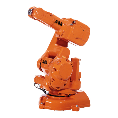
General The IRB 4400 is a 6-axis industrial robot, designed specifically for manufacturing
industries that use flexible robot-based automation. The robot has built-in process
ware, an open structure that is specially adapted for flexible use, and can
communicate extensively with external systems.
Different versions The IRB 4400 comes in several different versions, with handling capacities of
up to 60 kg, a maximum reach of 2.5 m, floor or shelf-mounted manipulators as well
as manipulators for harsh environments.
Foundry robots The robot version Foundry is suitable for operating in harsh environments and has
specialsurfacetreatment and paint forexcellent corrosion protection. The connectors
are designed for severe environments, and bearings, gears and other sensitive parts
are highly protected. The robots have the FoundryPlus protection which means that
the whole manipulator is IP67 classified and steam washable.
Foundry Prime The robot version Foundry Prime is designed for water jet cleaning of casts and
machined parts, and similar very harsh environments.
The manipulator can withstand surrounding solvent based detergent (max. pH 9.0
and must contain rust inhibitor). The detergent must be approved by ABB. In addi-
tion, the manipulator can withstand indirect spray from jet pressure (max. 600 bar)
and 100% humidity. The manipulator can work in an environment with a cleaning
bath temperature < 60oC, typically used in a water jet cleaning application with
moderate speed.
The robot is protected by special sealings for gears and bearings, pressurized motors
andelectroniccompartment,specialdetergentresistant polyurethane painting system
inthree layers.Non painted surfaceshas a specialrustpreventive coating, andmotors
are sealed with a sealing compound.
As the robot is designed for very harsh environments, an extended service and main-
tenance program is required. For detailed information of the maintenance program,
see chapter Maintenance in the Product Manual.
The protection, Foundry Prime is only available for robot version IRB 4400/60.
See chapter Specification of Variants and Options for options not selectable together
with Foundry Prime.

1 Description
1.1.1 Introduction
8 Rev.N 3HAC9117-1
Clean Room robots The Clean Room robots are classified for clean room class 100 according to US
Federal Standard 209 or class 5 according to ISO 14644-1.
The performed clean room test has classify the air cleanliness exclusively in terms of
concentration of airborne particles generated by the robot. Other aspects of the clean
room test or other clean room requirements are not considered.
Operating system The robot is equipped with the IRC5 controller and robot control software,
RobotWare.
RobotWare supports every aspect of the robot system, such as motion control,
development and execution of application programs, communication etc. See
Product specification - Controller IRC5 with FlexPendant.
Safety standards require a controller to be connected to the robot.
For additional functionality, the robot can be equipped with optional software for
application support - for example gluing and arc welding, communication features -
network communication - and advanced functions such as multitasking, sensor
control etc. For a complete description on optional software, see the Product
specification - Controller software IRC5/RobotWare.
Figure 1 The IRB 4400 manipulator has 6 axes.

1 Description
1.1.2 Different robot versions
3HAC9117-1 Rev.N 9
1.1.2 Different robot versions
General The IRB 4400 is available in five different versions.
1.1.3 Definition of version designation
IRB 4400 Version Handling capacity:
Manipulator weight
Other technical data
Robot type Handling capacity (kg) Reach (m)
IRB 4400/45 45 kg 1.96 m
IRB 4400/60 60 kg 1.96 m
IRB 4400/L30 30 kg 2.43 m
IRB 4400/L10 10 kg 2.55 m
IRB 4450S 30 kg 2.40 m
Prefix
description Robot
type Description
Version L
SLong arm
Shelf mounted manipulator
Handling capacity Indicates the maximum handling capacity (kg)
Robot type Weight
IRB 4400/45 985 kg
IRB 4400/60 1040 kg
IRB 4400/L10 1040 kg
IRB 4400/L30 1060 kg
IRB 4450/S 1040 kg
Data Description Note
Airborne noise level The sound pressure level out-
side the working space < 70 dB (A) Leq (acc. to Machinery
directive 89/392 EEC)

1 Description
1.1.3 Definition of version designation
10 Rev.N 3HAC9117-1
Power consumption Path E1-E2-E3-E4 in the ISO Cube, maximum load.
IRB 4400/45 (Cube side = 630 mm)
IRB 4400/60 (Cube side = 630 mm)
Figure 2 Path E1-E2-E3-E4 in the ISO Cube, maximum load.
Speed [mm/s] Power consumption [kW]
Max. 1.36
1000 0.95
500 0.74
100 0.62
Speed [mm/s] Power consumption [kW]
Max. 1.33
1000 0.99
500 0.78
100 0.66

1 Description
1.1.3 Definition of version designation
3HAC9117-1 Rev.N 11
IRB 4400/L30 (Cube side = 1000 mm)
IRB 4400/L10 (Cube side = 1000 mm)
Figure 3 Path E1-E2-E3-E4 in the ISO Cube, maximum load.
IRB 4450/S (Cube side = 1000 mm)
Speed [mm/s] Power consumption [kW]
Max. 1.15
1000 0.86
500 0.73
100 0.64
Speed [mm/s] Power consumption [kW]
Max. 1.28
1000 0.63
500 0.53
100 0.48
Speed [mm/s] Power consumption [kW]
Max. Not yet available
1000 Not yet available
500 Not yet available
100 Not yet available

1 Description
1.1.3 Definition of version designation
12 Rev.N 3HAC9117-1
Dimensions IRB 4400/45, IRB 4400/60, IRB 4400/L30:
Figure 4 View of the manipulator from the side (dimensions in mm).
Pos Description
A880 for 4400/45 and /60
B1380 for 4400/L30

1 Description
1.1.3 Definition of version designation
3HAC9117-1 Rev.N 13
Figure 5 View of the manipulator from the side (dimensions in mm).
IRB 4400/45, IRB 4400/60 and IRB 4400/L30:
Figure 6 View of the manipulator from above (dimensions in mm).

1 Description
1.1.3 Definition of version designation
14 Rev.N 3HAC9117-1
IRB 4400/L10:
Figure 7 View of the manipulator from the side and above (dimensions in mm).

1 Description
1.1.3 Definition of version designation
3HAC9117-1 Rev.N 15
IRB 4450/S:
Figure 8 View of the manipulator from the side, behind and above (dimensions in mm).

1 Description
1.2.1 Standards
16 Rev.N 3HAC9117-1
1.2 Safety/Standards
1.2.1 Standards
The robot conforms to the following standards:
The robot complies fully with the health and safety standards specified in the EEC’s
Machinery Directives.
Standard Description
EN ISO 12100-1 Safety of machinery, terminology
EN ISO 12100-2 Safety of machinery, technical specifications
EN 954-1 Safety of machinery, safety related parts of control systems
EN 60204 Electrical equipment of industrial machines
EN ISO 60204-1:2006 Safety of machinery - Electrical equipment of machines
EN ISO 10218-1:2006a
a. There is a deviation from paragraph 6.2 in that only worst case stop distances and
stop times are documented.
Robots for industrial environments - Safety requirements
EN 61000-6-4 (option) EMC, Generic emission
EN 61000-6-2 EMC, Generic immunity
Standard Description
IEC 60529 Degrees of protection provided by enclosures
Standard Description
ISO 9787 Manipulating industrial robots, coordinate systems and motions
Standard Description
ANSI/RIA 15.06/1999 Safety Requirements for Industrial Robots and Robot Systems
ANSI/UL 1740-1998
(option) Safety Standard for Robots and Robotic Equipment
CAN/CSA Z 434-03
(option) Industrial Robots and Robot Systems - General Safety Require-
ments

1 Description
1.2.2 Safety
3HAC9117-1 Rev.N 17
1.2.2 Safety
The robot is designed with absolute safety in mind. It has a dedicated safety system
based on a two-channel circuit which is monitored continuously. If any component
fails, the electrical power supplied to the motors shuts off and the brakes engage.
Safety category 3 Malfunction of a single component, such as a sticking relay, will be detected at the
next MOTOR OFF/MOTOR ON operation. MOTOR ON is then prevented and the
faulty section is indicated. This complies with category 3 of EN 954-1, Safety of
machinery - safety related parts of control systems - Part 1.
Selecting the operating mode
The robot can be operated either manually or automatically. In manual mode, the
robot can only be operated via the FlexPendant, that is not by any external
equipment.
Reduced speed In manual mode, the speed is limited to a maximum of 250 mm/s (600 inch/min.).
The speed limitation applies not only to the TCP (Tool Center Point), but to all parts
of the robot. It is also possible to monitor the speed of equipment mounted on the
robot.
Three position enabling device
The enabling device on the FlexPendant must be used to move the robot when in
manual mode. The enabling device consists of a switch withthree positions, meaning
that all robot movements stop when either the enabling device is pushed fully in, or
when it is released completely. This makes the robot safer to operate.
Safe manual movement
The robot is moved using a joystick instead of the operator having to look at the
FlexPendant to find the right key.
Over-speed protection
The speed of the robot is monitored by two independent computers.
Emergency stop There is one emergency stop push button on the controller and another on the
FlexPendant. Additional emergency stop buttons can be connected to the robot’s
safety chain circuit.

1 Description
1.2.2 Safety
18 Rev.N 3HAC9117-1
Safeguarded space stop
The robot has a number of electrical inputs which can be used to connect external
safety equipment, such as safety gates and light curtains. This allows the robot’s
safety functions to be activated both by peripheral equipment and by the robot itself.
Delayed safeguarded space stop
A delayed stop gives a smooth stop. The robot stops in the same way as at a normal
program stop with no deviation from the programmed path. After approx. 1 second
the power supplied to the motors shuts off.
Collision detection (option)
In case of an unexpected mechanical disturbance like a collision, electrode sticking
etc., the robot will stop and slightly back off from its stop position.
Restricting the working space
The movement of each axis can be restricted using software limits.
Axes 1-2 can also be restricted by means of mechanical stops and axis 3 by an
electrical switch (option).
Hold-to-run control “Hold-to-run” means that you must depress the start button in order to move the
robot. When the button is released the robot will stop. The hold-to-run function
makes program testing safer.
Fire safety Both the manipulator and control system comply with UL’s (Underwriters
Laboratories) tough requirements for fire safety.
Safety lamp (option) The robot can be equipped with a safety lamp mounted on the manipulator. This is
activated when the motors are in the MOTORS ON state.
This manual suits for next models
5
Table of contents
Other ABB Robotics manuals

ABB
ABB DressPack IRB 6620 User manual

ABB
ABB FlexLoader Instructions for use

ABB
ABB IRB 120 Owner's manual

ABB
ABB IRB 6710 User manual

ABB
ABB IRB 910INV User manual

ABB
ABB IRB 6650S User manual

ABB
ABB IRB 7600 User manual

ABB
ABB IRB 6700Inv User manual

ABB
ABB IRB 260 User manual

ABB
ABB IRB 6650S - 200/3.0 User manual
Popular Robotics manuals by other brands

Denso
Denso VP-G SERIES Installation & maintenance guide

YZ Robot
YZ Robot DSR02B user manual

ROKAE
ROKAE xMate CR12 Hardware installation manual

ALDEBARAN Robotics
ALDEBARAN Robotics NAO 3.3 quick guide

PLEN Robotics
PLEN Robotics Cube PC020B instruction manual

Thames & Kosmos
Thames & Kosmos SIDEKICK Experiment manual