ABB IRB 120 Owner's manual

ROBOTICS
Product specification
IRB 120

Trace back information:
Workspace OmniCore and R19C version a16
Checked in 2019-09-16
Skribenta version 5.3.012

Product specification
IRB 120
IRC5
Document ID: 3HAC035960-001
Revision: T
© Copyright 2010-2019 ABB. All rights reserved.
Specifications subject to change without notice.

The information in this manual is subject to change without notice and should not
be construed as a commitment by ABB. ABB assumes no responsibility for any errors
that may appear in this manual.
Except as may be expressly stated anywhere in this manual, nothing herein shall be
construed as any kind of guarantee or warranty by ABB for losses, damages to
persons or property, fitness for a specific purpose or the like.
In no event shall ABB be liable for incidental or consequential damages arising from
use of this manual and products described herein.
This manual and parts thereof must not be reproduced or copied without ABB's
written permission.
Keep for future reference.
Additional copies of this manual may be obtained from ABB.
Original instructions.
© Copyright 2010-2019 ABB. All rights reserved.
Specifications subject to change without notice.

Table of contents
7Overview of this specification ..........................................................................................................
91 Description
91.1 Structure ......................................................................................................... 91.1.1 Introduction to structure ........................................................................... 111.1.2 The robot ............................................................................................... 131.2 Standards ........................................................................................................ 131.2.1 Applicable standards ............................................................................... 151.3 Installation ....................................................................................................... 161.3.1 Operating requirements ............................................................................ 171.3.2 Mounting the manipulator ......................................................................... 201.4 Load diagram ................................................................................................... 201.4.1 Introduction to load diagrams .................................................................... 211.4.2 Load diagrams ........................................................................................
23
1.4.3 Maximum load and moment of inertia for full and limited axis 5 (center line down)
movement .............................................................................................. 251.5 Mounting of equipment ....................................................................................... 261.5.1 Holes for mounting extra equipment ........................................................... 281.6 Calibration ....................................................................................................... 281.6.1 Calibration methods ................................................................................. 291.6.2 Fine calibration ....................................................................................... 301.6.3 Absolute Accuracy option ......................................................................... 321.7 Maintenance and trouble shooting ........................................................................ 321.7.1 Introduction to maintenance and trouble shooting ......................................... 331.8 Robot motion .................................................................................................... 331.8.1 Working range and type of motion .............................................................. 351.8.2 Performance according to ISO 9283 ............................................................ 361.8.3 Velocity ................................................................................................. 371.8.4 Robot stopping distances and times ........................................................... 381.9 Customer connections ....................................................................................... 381.9.1 Introduction to customer connections .........................................................
392 Specification of variants and options
392.1 Introduction to variants and options ...................................................................... 402.2 Manipulator ...................................................................................................... 422.3 Floor cables ..................................................................................................... 432.4 Process ........................................................................................................... 442.5 User documentation ..........................................................................................
453 Accessories
453.1 Introduction to accessories .................................................................................
47Index
Product specification - IRB 120 5
3HAC035960-001 Revision: T
© Copyright 2010-2019 ABB. All rights reserved.
Table of contents

This page is intentionally left blank

Overview of this specification
About this product specification
It describes the performance of the manipulator or a complete family of manipulators
in terms of:
• The structure and dimensional prints
• The fulfilment of standards, safety and operating requirements
• The load diagrams, mounting of extra equipment, the motion and the robot
reach
• The specification of variants and options available
Usage
Product specifications are used to find data and performance about the product,
for example to decide which product to buy. How to handle the product is described
in the product manual.
Users
It is intended for:
• Product managers and product personnel
• Sales and marketing personnel
• Order and customer service personnel
References
Document IDReference
3HAC047400-001Product specification - Controller IRC5
IRC5 with main computer DSQC1000.
3HAC050945-001Product specification - Controller software IRC5
IRC5 with main computer DSQC1000 and RobotWare 5.6x.
3HAC050945-001Product specification - Controller software IRC5
IRC5 with main computer DSQC1000 and RobotWare 6.
3HAC048645-001Product specification - Robot stopping distances according to ISO 10218-
1
3HAC035728-001Product manual - IRB 120
3HAC050941-001Operating manual - IRC5 with FlexPendant
3HAC052355-001Product specification - Robot user documentation, IRC5 with RobotWare
6
Revisions
DescriptionRevision
New product specification-
Options 431-1 and 239-1 addedA
Standards updated, minor correctionsB
Size of washer for mounting the manipulator adjustedC
Continues on next page
Product specification - IRB 120 7
3HAC035960-001 Revision: T
© Copyright 2010-2019 ABB. All rights reserved.
Overview of this specification

DescriptionRevision
Table for ambient temperature is adjustedD
•Clean Room option added
• Machinery directive updated
E
• New robot variant added
• General corrections
F
• Added data for extended range of movement of axis 6.
• Changed the illustration that shows the mounting surface
of the tool flange.
G
• Minor corrections and updates
H
• Minor corrections and updates
J
• Text for ISO test adjusted
• Robot stopping distances and times for category 0 and
category 1 stops are moved to a separate document, Product
specification - Robot stopping distances according to ISO
10218-1.
K
• The list of applicable safety standards is updated. The IRB
120 does not comply with the CSA/UL standards, see Ap-
plicable standards on page 13.
• Minor corrections/update
L
• Minor corrections/update
M
• Clean Room option added
• Food grade lubrication option added
• Axis Calibration method added
N
Published in release R17.1. The following updates are done in this
revision:
• Minor corrections/update
• Restriction of Load diagram added
• Add options of Connection of parallell communication
P
Published in release R17.2. The following updates are done in this
revision:
• Change the drawing of Load diagrams.
• Updated list of applicable standards.
Q
Published in release R18.2. The following updates are done in this
revision:
• Update customer connector description.
R
Published in release R19B The following updates are done in this
revision:
• 435-109 IRB 120T-3/0.6 phased out.
• Updated information about Absolute Accuracy.
S
Published in release R19C The following updates are done in this
revision:
• Minor change in Ambient temperature section.
• Note added about need to calibrate if the robot is other than
floor mounted.
T
8 Product specification - IRB 120
3HAC035960-001 Revision: T
© Copyright 2010-2019 ABB. All rights reserved.
Overview of this specification
Continued
1 Description
1.1 Structure
1.1.1 Introduction to structure
General
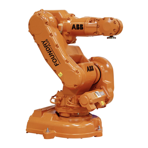
The IRB 120 is one of ABB Robotics latest generation of 6-axis industrial robot,
with a payload of 3 kg, designed specifically for manufacturing industries that use
flexible robot-based automation, e.g. 3C industry.
The robot has an open structure that is especially adapted for flexible use, and
can communicate extensively with external systems.
Clean room robots
xx1100000959
Particle emission from the robot fulfill Clean room class 5 standard according to
DIN EN ISO 14644-1.
Clean room robots are specially designed to work in a clean room environment.
According to IPA test result, the robot IRB 120 is suitable for use in Clean Room
environment.
Clean room robots are designed in order to prevent from particle emission from
the robot. For example is, frequent maintenance work possible to perform without
cracking the paint. The robot is painted with four layers of polyurethane paint. The
last layer being a varnish over labels in order to simplify cleaning. The paint has
been tested regarding outgassing of Volatile Organic Compounds (VOC) and been
classified in accordance with ISO 14644-8.
Classification of airborne molecular contamination, see below:
Outgassing amountParameter
Classifica-
tion in ac-
cordance to
ISO 14644-
8
Normed
based on
1m2and
1s(g)
Total detec-
ted (ng)
Performed
test
Temp (°C)Test dura-
tion (s)
Area (m2)
-6.81.7E-072848TVOC2336004.5E-03
-3.81.7E-0446524TVOC90604.5E-03
Classification results in accordance with ISO 14644-8 at different test temperatures.
Food grade lubrication
The robot has food grade lubrication (NSF H1) as an option. The protection type
for robots with food grade lubrication is Clean Room.
Continues on next page
Product specification - IRB 120 9
3HAC035960-001 Revision: T
© Copyright 2010-2019 ABB. All rights reserved.
1 Description
1.1.1 Introduction to structure

Operating system
The robot is equipped with the IRC5 Compact or IRC5 (Single cabinet) controller
and robot control software, RobotWare. RobotWare supports every aspect of the
robot system, such as motion control, development and execution of application
programs, communication etc. See Product specification - Controller IRC5 with
FlexPendant and Product specification - Controller software IRC5.
Safety
Safety standards valid for complete robot, manipulator and controller.
Additional functionality
For additional functionality, the robot can be equipped with optional software for
application support - for example gluing and welding, communication features -
network communication - and advanced functions such as multitasking, sensor
control etc. For a complete description on optional software, see Product
specification - Controller software IRC5.
Manipulator axes
Axis 1
Axis 2
-
Axis 3 Axis 4
+Axis 5
-
+
-
-
++Axis 6
+
-
-
+
xx0900000262
10 Product specification - IRB 120
3HAC035960-001 Revision: T
© Copyright 2010-2019 ABB. All rights reserved.
1 Description
1.1.1 Introduction to structure
Continued

1.1.2 The robot
General
The IRB 120-3/0.6 is available in two versions and both can be mounted on floor,
inverted or on wall in any angle (tilted around X or Y axis).
Reach (m)Handling capacity (kg)Robot type
0.58 m3 kgIRB 120
Manipulator weight
WeightData
25 kgIRB 120-3/0.6
Other technical data
NoteDescriptionData
< 70 dB (A) Leq (acc. to the work-
ing space Machinery directive
2006/42/EG)
The sound pressure level outsideAirborne noise level
Power consumption
Path E1-E2-E3-E4 in the ISO Cube, maximum load.
Power consumption (kW)Type of movement
0.24 kWISO Cube Max. velocity
IRB 120Robot in 0 degree position
0.095 kWBrakes engaged
0.173 kWBrakes disengaged
xx0900000265
DescriptionPosition
250 mmA
Continues on next page
Product specification - IRB 120 11
3HAC035960-001 Revision: T
© Copyright 2010-2019 ABB. All rights reserved.
1 Description
1.1.2 The robot

Dimensions IRB 120-3/0.6
72
463
90
180
302
187
284
700
270290 70
(B)
90
180
(C)
134
(A)
xx0900000256
DescriptionPosition
Minimum turning radius axis 1 R=121 mmA
Minimum turning radius axis 3 R=147 mmB
Minimum turning radius axis 4 R=70 mmC
12 Product specification - IRB 120
3HAC035960-001 Revision: T
© Copyright 2010-2019 ABB. All rights reserved.
1 Description
1.1.2 The robot
Continued

1.2 Standards
1.2.1 Applicable standards
Note
The listed standards are valid at the time of the release of this document. Phased
out or replaced standards are removed from the list when needed.
Standards, EN ISO
The product is designed in accordance with the requirements of:
DescriptionStandard
Safety of machinery - General principles for design - Risk as-
sessment and risk reduction
EN ISO 12100:2010
Safety of machinery, safety related parts of control systems -
Part 1: General principles for design
EN ISO 13849-1:2015
Safety of machinery - Emergency stop - Principles for designEN ISO 13850:2015
Robots for industrial environments - Safety requirements -Part
1 Robot
EN ISO 10218-1:2011
Robots and robotic devices -- Coordinate systems and motion
nomenclatures
ISO 9787:2013
Manipulating industrial robots, performance criteria, and related
test methods
ISO 9283:1998
Classification of air cleanlinessEN ISO 14644-1:2015i
Ergonomics of the thermal environment - Part 1EN ISO 13732-1:2008
EMC, Generic emissionEN 61000-6-4:2007 +
A1:2011
IEC 61000-6-4:2006 +
A1:2010
(option 129-1)
EMC, Generic immunityEN 61000-6-2:2005
IEC 61000-6-2:2005
Arc welding equipment - Part 1: Welding power sourcesEN IEC 60974-1:2012ii
Arc welding equipment - Part 10: EMC requirementsEN IEC 60974-10:2014ii
Safety of machinery - Electrical equipment of machines - Part
1 General requirements
EN IEC 60204-1:2006
Degrees of protection provided by enclosures (IP code)IEC 60529:1989 + A2:2013
iOnly robots with protection Clean Room.
ii Only valid for arc welding robots. Replaces EN IEC 61000-6-4 for arc welding robots.
European standards
DescriptionStandard
Safety of machinery - Ergonomic design principles - Part 1:
Terminology and general principles
EN 614-1:2006 + A1:2009
Continues on next page
Product specification - IRB 120 13
3HAC035960-001 Revision: T
© Copyright 2010-2019 ABB. All rights reserved.
1 Description
1.2.1 Applicable standards

DescriptionStandard
Safety of machinery - Two-hand control devices - Functional
aspects - Principles for design
EN 574:1996 + A1:2008
14 Product specification - IRB 120
3HAC035960-001 Revision: T
© Copyright 2010-2019 ABB. All rights reserved.
1 Description
1.2.1 Applicable standards
Continued

1.3 Installation
General
IRB 120 is adapted for normal industrial environment. An end effector, weighing a
maximum of 3 kg, including payload, can be mounted on the robot’s mounting
flange (axis 6). Other equipment, weighing a maximum of 0.3 kg, can be mounted
on the upper arm. For more information about mounting of extra equipment, see
Figure on next page.
Continues on next page
Product specification - IRB 120 15
3HAC035960-001 Revision: T
© Copyright 2010-2019 ABB. All rights reserved.
1 Description
1.3 Installation

1.3.1 Operating requirements
Protection standard
IEC529Protection standard
IP30All variants, manipulator
Explosive environments
The robot must not be located or operated in an explosive environment.
Working range limitations
It is not possible to select EPS together with IRC5 Compact. No mechanical
limitation.
Ambient temperature
TemperatureProtection classDescription
+ 5°C i(41°F) to + 45°C (113°F)StandardManipulator during opera-
tion
+ 5°C i(41°F) to + 35°C ii (95°F)OptionManipulator with food
grade lubrication during
operation
Product specification - Controller
IRC5 with FlexPendant
Standard/OptionFor the controller
- 25°C (-13°F) to + 55°C (131°F)StandardComplete robot during
transportation and storage
up to + 70°C (158°F)StandardFor short periods (not ex-
ceeding 24 hours)
iAt low environmental temperature < 10ºC is, as with any other machine, a warm-up phase
recommended to be run with the robot. Otherwise there is a risk that the robot stops or run with
lower performance due to temperature dependent oil and grease viscosity.
ii For robots with food grade lubrication, if environment temperature > 35ºC, contact ABB for further
information.
Relative humidity
Relative humidityDescription
Max. 95% at constant temperatureComplete robot during operation, transportation and
storage
16 Product specification - IRB 120
3HAC035960-001 Revision: T
© Copyright 2010-2019 ABB. All rights reserved.
1 Description
1.3.1 Operating requirements

1.3.2 Mounting the manipulator
Maximum load
Maximum load in relation to the base coordination system. See Figure below.
Floor Mounted
Max. load (emergency stop)Endurance load (in operation)Force
±515 N±265 NForce xy
-265 ±365 N-265 ±200 NForce z
±400 Nm±195 NmTorque xy
±155 Nm±85 NmTorque z
Wall Mounted
Max. load (emergency stop)Endurance load (in operation)Force
±735 N±470 NForce xy
0 ±630 N0 ±200 NForce z
±450 Nm±240 NmTorque xy
±175 Nm±90 NmTorque z
Suspended
Max. load (emergency stop)Endurance load (in operation)Force
±515 N±265 NForce xy
265 ±365 N265 ±200 NForce z
±400 Nm±195 NmTorque xy
±155 Nm±85 NmTorque z
Continues on next page
Product specification - IRB 120 17
3HAC035960-001 Revision: T
© Copyright 2010-2019 ABB. All rights reserved.
1 Description
1.3.2 Mounting the manipulator

Torque (M )
Force (F )
Force (F )
Torque (M )
xy
z
zz
z
xy
xy xy
xx0900000257
Note regarding Mxy and Fxy
The bending torque (Mxy) can occur in any direction in the XY-plane of the base
coordinate system.The same applies to the transverse force (Fxy).
Continues on next page
18 Product specification - IRB 120
3HAC035960-001 Revision: T
© Copyright 2010-2019 ABB. All rights reserved.
1 Description
1.3.2 Mounting the manipulator
Continued

Fastening holes robot base
+
81
59
75
75
75 75
2x
6
H8
0
0.02
81
59
E
E
0.15
4x
12
4x
22
4x
12
4x
14.3
E-E
0.5
xx0900000258
Attachment bolts, specification
The table below specifies required bolts and washers for securing the robot at
installation site.
DescriptionSpecification
M10 x 25 (installation directly on foundation)Attachment bolts, 4 pcs
D=6x20Guide pins, 2 pcs
10.5 x 20 x 2Washers, 4 pcs
Quality 8.8Quality
47 NmTightening torque
Product specification - IRB 120 19
3HAC035960-001 Revision: T
© Copyright 2010-2019 ABB. All rights reserved.
1 Description
1.3.2 Mounting the manipulator
Continued

1.4 Load diagram
1.4.1 Introduction to load diagrams
Information
WARNING
It is very important to always define correct actual load data and correct payload
of the robot. Incorrect definitions of load data can result in overloading of the
robot.
If incorrect load data and/or loads are outside load diagram is used the following
parts can be damaged due to overload:
• motors
• gearboxes
• mechanical structure
WARNING
In the robot system there is a service routine called LoadIdentify available, which
allows the user to make an automatic definition of the tool and load, to determine
correct load parameters. See Operating manual - IRC5 with FlexPendant.
WARNING
Robots running with incorrect load data and/or with loads outside diagram, will
not be covered by robot warranty.
General
The load diagram includes a nominal pay load inertia, J0of 0.012 kgm2and an
extra load of 0.3 kg at the upper arm housing. At different moment of inertia the
load diagram will be changed. For robots that are allowed tilted, wall or inverted
mounted, the load diagrams as given are valid and thus it is also possible to use
RobotLoad within those tilt and axis limits.
Control of load case with RobotLoad
To easily control a specific load case, use the calculation program ABB RobotLoad.
Contact your local ABB organization for more information.
The result from RobotLoad is only valid within the maximum loads and tilt angles.
There is no warning if the maximum permitted armload is exceeded. For over load
cases and special applications, contact ABB for further analysis.
20 Product specification - IRB 120
3HAC035960-001 Revision: T
© Copyright 2010-2019 ABB. All rights reserved.
1 Description
1.4.1 Introduction to load diagrams
Other manuals for IRB 120
2
Table of contents
Other ABB Robotics manuals

ABB
ABB IRB 7600 User manual

ABB
ABB OmniCore E10 User manual

ABB
ABB CRB 1100 User manual

ABB
ABB IRB 365 User manual

ABB
ABB IRB 1200 User manual

ABB
ABB OmniCore V250XT Type B User manual

ABB
ABB IRB 5720 User manual

ABB
ABB IRB 2600 Series User manual

ABB
ABB IRB 1300 User manual

ABB
ABB FlexLoader Vision User manual

ABB
ABB IRC5 Compact User manual

ABB
ABB IRB 6620LX User manual

ABB
ABB IRB 2400/10 Owner's manual

ABB
ABB IRB 1200 Owner's manual

ABB
ABB CRB 15000 User manual

ABB
ABB OmniCore User manual

ABB
ABB DressPack IRB 6620 User manual

ABB
ABB IRB 1200-5/0.9 User manual

ABB
ABB IRB 6730 User manual

ABB
ABB IRB 7600 Series User manual