ABB IRB 6620 Owner's manual

Product specification
Articulated robot
IRB 6620-150/2.2
M2004


Product specification
Articulated robot
3HAC025861-001
Rev.E
IRB 6620 - 150/2.2
M2004

The information in this manual issubject to change without notice and shouldnotbe construed
as a commitment by ABB. ABB assumes no responsibility for any errors that may appear in
this manual.
Exceptas may beexpresslystatedanywhere in this manual,nothing herein shall be construed
as any kind of guarantee or warranty by ABB for losses, damages to persons or property, fit-
ness for a specific purpose or the like.
In no event shall ABB be liable for incidental or consequential damages arising from use of
this manual and products described herein.
This manual and parts thereof must not be reproduced or copied without ABB's written per-
mission, and contents thereof must not be imparted to a third party nor be used for any unau-
thorized purpose. Contravention will be prosecuted.
Additional copies of this manual may be obtained from ABB at its then current charge.
©Copyright 2006 ABB All right reserved.
ABB AB
Robotics Products
SE-721 68 Västerås
Sweden

Table of Contents
3HAC 025861-001 Rev.E 3
Overview 5
1 Description 7
1.1 Structure. . . . . . . . . . . . . . . . . . . . . . . . . . . . . . . . . . . . . . . . . . . . . . . . . . . . . . . . . . . . . . . . . . . . . . . . .7
1.1.1 Introduction . . . . . . . . . . . . . . . . . . . . . . . . . . . . . . . . . . . . . . . . . . . . . . . . . . . . . . . . . . . . . . . .7
1.1.2 The Robot. . . . . . . . . . . . . . . . . . . . . . . . . . . . . . . . . . . . . . . . . . . . . . . . . . . . . . . . . . . . . . . . . .8
1.2 Safety/Standards . . . . . . . . . . . . . . . . . . . . . . . . . . . . . . . . . . . . . . . . . . . . . . . . . . . . . . . . . . . . . . . . .10
1.2.1 Standards . . . . . . . . . . . . . . . . . . . . . . . . . . . . . . . . . . . . . . . . . . . . . . . . . . . . . . . . . . . . . . . . .10
1.3 Installation . . . . . . . . . . . . . . . . . . . . . . . . . . . . . . . . . . . . . . . . . . . . . . . . . . . . . . . . . . . . . . . . . . . . . .14
1.3.1 Introduction . . . . . . . . . . . . . . . . . . . . . . . . . . . . . . . . . . . . . . . . . . . . . . . . . . . . . . . . . . . . . . .14
1.3.2 Operating requirements . . . . . . . . . . . . . . . . . . . . . . . . . . . . . . . . . . . . . . . . . . . . . . . . . . . . . .15
1.3.3 Mounting the manipulator . . . . . . . . . . . . . . . . . . . . . . . . . . . . . . . . . . . . . . . . . . . . . . . . . . . .16
1.4 Calibration and references . . . . . . . . . . . . . . . . . . . . . . . . . . . . . . . . . . . . . . . . . . . . . . . . . . . . . . . . .21
1.4.1 Fine calibration. . . . . . . . . . . . . . . . . . . . . . . . . . . . . . . . . . . . . . . . . . . . . . . . . . . . . . . . . . . . .21
1.4.2 Absolute Accuracy calibration. . . . . . . . . . . . . . . . . . . . . . . . . . . . . . . . . . . . . . . . . . . . . . . . .22
1.4.3 Robot references. . . . . . . . . . . . . . . . . . . . . . . . . . . . . . . . . . . . . . . . . . . . . . . . . . . . . . . . . . . .24
1.5 Load diagrams . . . . . . . . . . . . . . . . . . . . . . . . . . . . . . . . . . . . . . . . . . . . . . . . . . . . . . . . . . . . . . . . . . .25
1.5.1 Introduction . . . . . . . . . . . . . . . . . . . . . . . . . . . . . . . . . . . . . . . . . . . . . . . . . . . . . . . . . . . . . . .25
1.5.2 Diagrams . . . . . . . . . . . . . . . . . . . . . . . . . . . . . . . . . . . . . . . . . . . . . . . . . . . . . . . . . . . . . . . . .26
1.5.3 Maximum load and moment of inertia for full and limited axis 5 (center line down)
movement. . . . . . . . . . . . . . . . . . . . . . . . . . . . . . . . . . . . . . . . . . . . . . . . . . . . . . . . . . . . . . . . .28
1.5.4 Wrist torque . . . . . . . . . . . . . . . . . . . . . . . . . . . . . . . . . . . . . . . . . . . . . . . . . . . . . . . . . . . . . . .29
1.6 Mounting of equipment. . . . . . . . . . . . . . . . . . . . . . . . . . . . . . . . . . . . . . . . . . . . . . . . . . . . . . . . . . . .30
1.6.1 General. . . . . . . . . . . . . . . . . . . . . . . . . . . . . . . . . . . . . . . . . . . . . . . . . . . . . . . . . . . . . . . . . . .30
1.7 Maintenance and Troubleshooting . . . . . . . . . . . . . . . . . . . . . . . . . . . . . . . . . . . . . . . . . . . . . . . . . .34
1.7.1 Introduction . . . . . . . . . . . . . . . . . . . . . . . . . . . . . . . . . . . . . . . . . . . . . . . . . . . . . . . . . . . . . . .34
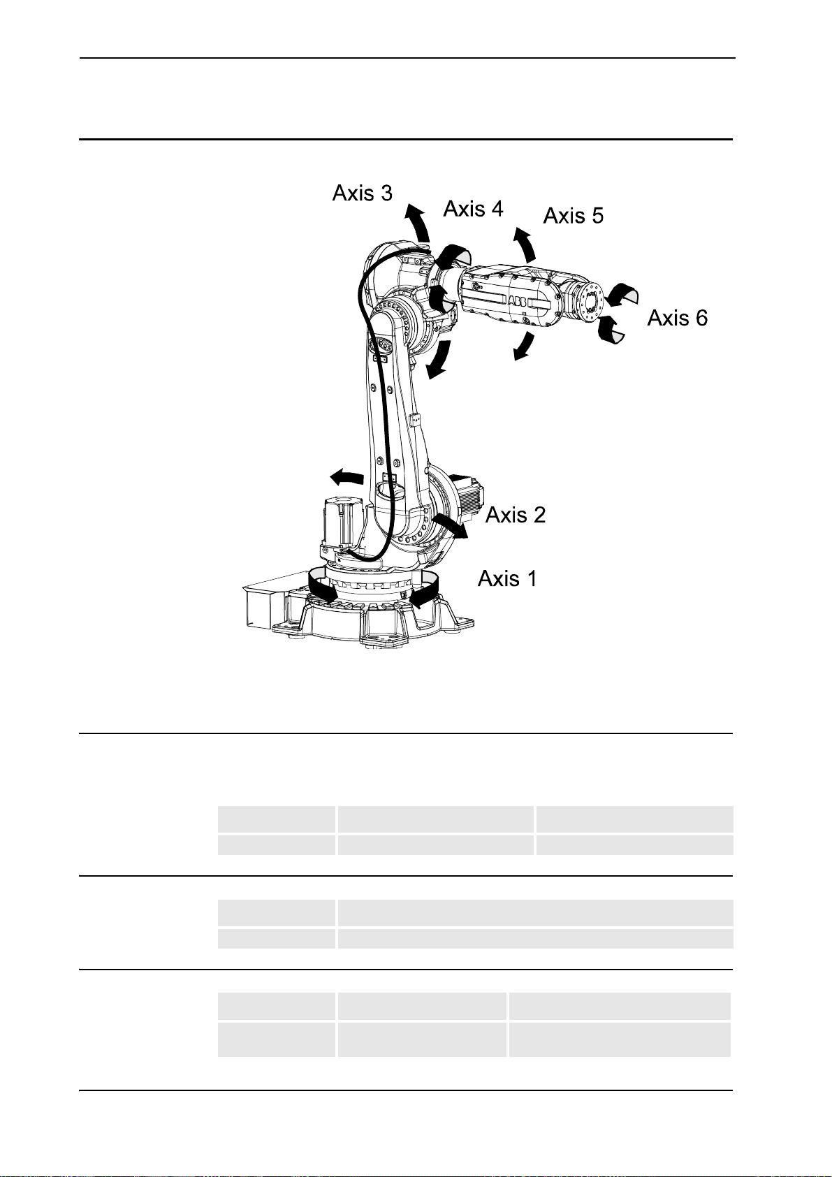
1.8 Robot Motion . . . . . . . . . . . . . . . . . . . . . . . . . . . . . . . . . . . . . . . . . . . . . . . . . . . . . . . . . . . . . . . . . . . .35
1.8.1 Introduction . . . . . . . . . . . . . . . . . . . . . . . . . . . . . . . . . . . . . . . . . . . . . . . . . . . . . . . . . . . . . . .35
1.8.2 Performance according to ISO 9283 . . . . . . . . . . . . . . . . . . . . . . . . . . . . . . . . . . . . . . . . . . . .38
1.8.3 Velocity . . . . . . . . . . . . . . . . . . . . . . . . . . . . . . . . . . . . . . . . . . . . . . . . . . . . . . . . . . . . . . . . . .39
1.8.4 Stopping distance/time. . . . . . . . . . . . . . . . . . . . . . . . . . . . . . . . . . . . . . . . . . . . . . . . . . . . . . .39
1.9 Servo Gun. . . . . . . . . . . . . . . . . . . . . . . . . . . . . . . . . . . . . . . . . . . . . . . . . . . . . . . . . . . . . . . . . . . . . . .40
1.9.1 Introduction . . . . . . . . . . . . . . . . . . . . . . . . . . . . . . . . . . . . . . . . . . . . . . . . . . . . . . . . . . . . . . .40
1.9.2 Stationary Gun . . . . . . . . . . . . . . . . . . . . . . . . . . . . . . . . . . . . . . . . . . . . . . . . . . . . . . . . . . . . .41
1.9.3 Robot Gun . . . . . . . . . . . . . . . . . . . . . . . . . . . . . . . . . . . . . . . . . . . . . . . . . . . . . . . . . . . . . . . .42
1.9.4 Robot Gun and Track Motion . . . . . . . . . . . . . . . . . . . . . . . . . . . . . . . . . . . . . . . . . . . . . . . . .43
1.9.5 Track Motion IRBT 6004. . . . . . . . . . . . . . . . . . . . . . . . . . . . . . . . . . . . . . . . . . . . . . . . . . . . .44
2 DressPack and SpotPack 45
2.1 Introduction . . . . . . . . . . . . . . . . . . . . . . . . . . . . . . . . . . . . . . . . . . . . . . . . . . . . . . . . . . . . . . . . . . . . .45
2.1.1 General. . . . . . . . . . . . . . . . . . . . . . . . . . . . . . . . . . . . . . . . . . . . . . . . . . . . . . . . . . . . . . . . . . .45
2.1.2 Product range . . . . . . . . . . . . . . . . . . . . . . . . . . . . . . . . . . . . . . . . . . . . . . . . . . . . . . . . . . . . . .47
2.1.3 Limitations of robot movements . . . . . . . . . . . . . . . . . . . . . . . . . . . . . . . . . . . . . . . . . . . . . . .48
2.1.4 Impact on dress pack lifetime. . . . . . . . . . . . . . . . . . . . . . . . . . . . . . . . . . . . . . . . . . . . . . . . . .48
2.1.5 Chapter Structure . . . . . . . . . . . . . . . . . . . . . . . . . . . . . . . . . . . . . . . . . . . . . . . . . . . . . . . . . . .49
2.2 DressPack. . . . . . . . . . . . . . . . . . . . . . . . . . . . . . . . . . . . . . . . . . . . . . . . . . . . . . . . . . . . . . . . . . . . . . .50
2.2.1 Introduction . . . . . . . . . . . . . . . . . . . . . . . . . . . . . . . . . . . . . . . . . . . . . . . . . . . . . . . . . . . . . . .50
2.2.2 Build-in features for upper arm DressPack . . . . . . . . . . . . . . . . . . . . . . . . . . . . . . . . . . . . . . .53
2.2.3 Interface description for DressPack . . . . . . . . . . . . . . . . . . . . . . . . . . . . . . . . . . . . . . . . . . . . .54

Table of Contents
4 Rev.E 3HAC 025861-001
2.3 Type H. . . . . . . . . . . . . . . . . . . . . . . . . . . . . . . . . . . . . . . . . . . . . . . . . . . . . . . . . . . . . . . . . . . . . . . . . . 61
2.3.1 Introduction . . . . . . . . . . . . . . . . . . . . . . . . . . . . . . . . . . . . . . . . . . . . . . . . . . . . . . . . . . . . . . .61
2.3.2 Configuration result for Type H . . . . . . . . . . . . . . . . . . . . . . . . . . . . . . . . . . . . . . . . . . . . . . .64
2.4 Type Se. . . . . . . . . . . . . . . . . . . . . . . . . . . . . . . . . . . . . . . . . . . . . . . . . . . . . . . . . . . . . . . . . . . . . . . . . 67
2.4.1 Introduction . . . . . . . . . . . . . . . . . . . . . . . . . . . . . . . . . . . . . . . . . . . . . . . . . . . . . . . . . . . . . . .67
2.4.2 Configuration result for Type Se . . . . . . . . . . . . . . . . . . . . . . . . . . . . . . . . . . . . . . . . . . . . . . .70
2.5 Type HSe . . . . . . . . . . . . . . . . . . . . . . . . . . . . . . . . . . . . . . . . . . . . . . . . . . . . . . . . . . . . . . . . . . . . . . .76
2.5.1 Introduction . . . . . . . . . . . . . . . . . . . . . . . . . . . . . . . . . . . . . . . . . . . . . . . . . . . . . . . . . . . . . . .76
2.5.2 Configuration result for Type HSe . . . . . . . . . . . . . . . . . . . . . . . . . . . . . . . . . . . . . . . . . . . . .79
2.5.3 Interface description stationary gun. . . . . . . . . . . . . . . . . . . . . . . . . . . . . . . . . . . . . . . . . . . . .84
2.6 Spot Welding cabinet . . . . . . . . . . . . . . . . . . . . . . . . . . . . . . . . . . . . . . . . . . . . . . . . . . . . . . . . . . . . .86
2.6.1 Introduction . . . . . . . . . . . . . . . . . . . . . . . . . . . . . . . . . . . . . . . . . . . . . . . . . . . . . . . . . . . . . . .86
2.6.2 Interface description Spot Welding cabinet. . . . . . . . . . . . . . . . . . . . . . . . . . . . . . . . . . . . . . .94
2.7 Water and Air unit . . . . . . . . . . . . . . . . . . . . . . . . . . . . . . . . . . . . . . . . . . . . . . . . . . . . . . . . . . . . . . . . 96
2.7.1 Introduction . . . . . . . . . . . . . . . . . . . . . . . . . . . . . . . . . . . . . . . . . . . . . . . . . . . . . . . . . . . . . . .96
2.7.2 Technical data Water and Air unit. . . . . . . . . . . . . . . . . . . . . . . . . . . . . . . . . . . . . . . . . . . . .104
2.8 Tip Dresser. . . . . . . . . . . . . . . . . . . . . . . . . . . . . . . . . . . . . . . . . . . . . . . . . . . . . . . . . . . . . . . . . . . . .105
2.8.1 Introduction . . . . . . . . . . . . . . . . . . . . . . . . . . . . . . . . . . . . . . . . . . . . . . . . . . . . . . . . . . . . . .105
2.9 Connection kits . . . . . . . . . . . . . . . . . . . . . . . . . . . . . . . . . . . . . . . . . . . . . . . . . . . . . . . . . . . . . . . . . 109
2.9.1 Options. . . . . . . . . . . . . . . . . . . . . . . . . . . . . . . . . . . . . . . . . . . . . . . . . . . . . . . . . . . . . . . . . .109
3 Specification of Variants and Options 115
3.1 Introduction . . . . . . . . . . . . . . . . . . . . . . . . . . . . . . . . . . . . . . . . . . . . . . . . . . . . . . . . . . . . . . . . . . . .115
3.1.1 General. . . . . . . . . . . . . . . . . . . . . . . . . . . . . . . . . . . . . . . . . . . . . . . . . . . . . . . . . . . . . . . . . .115
3.1.2 Manipulator . . . . . . . . . . . . . . . . . . . . . . . . . . . . . . . . . . . . . . . . . . . . . . . . . . . . . . . . . . . . . .115
3.1.3 Equipment . . . . . . . . . . . . . . . . . . . . . . . . . . . . . . . . . . . . . . . . . . . . . . . . . . . . . . . . . . . . . . . 116
3.1.4 Floor cables . . . . . . . . . . . . . . . . . . . . . . . . . . . . . . . . . . . . . . . . . . . . . . . . . . . . . . . . . . . . . .123
3.1.5 Process DressPack . . . . . . . . . . . . . . . . . . . . . . . . . . . . . . . . . . . . . . . . . . . . . . . . . . . . . . . . . 123
3.1.6 DressPack Floor. . . . . . . . . . . . . . . . . . . . . . . . . . . . . . . . . . . . . . . . . . . . . . . . . . . . . . . . . . .124
3.1.7 DressPack Lower/Upper arm. . . . . . . . . . . . . . . . . . . . . . . . . . . . . . . . . . . . . . . . . . . . . . . . .124
3.1.8 Connection Kits . . . . . . . . . . . . . . . . . . . . . . . . . . . . . . . . . . . . . . . . . . . . . . . . . . . . . . . . . . .125
3.1.9 Servo Gun . . . . . . . . . . . . . . . . . . . . . . . . . . . . . . . . . . . . . . . . . . . . . . . . . . . . . . . . . . . . . . . 125
3.1.10 SpotPack Floor Cables. . . . . . . . . . . . . . . . . . . . . . . . . . . . . . . . . . . . . . . . . . . . . . . . . . . . .126
3.1.11 Tip Dresser. . . . . . . . . . . . . . . . . . . . . . . . . . . . . . . . . . . . . . . . . . . . . . . . . . . . . . . . . . . . . .127
3.1.12 Process Cabinet . . . . . . . . . . . . . . . . . . . . . . . . . . . . . . . . . . . . . . . . . . . . . . . . . . . . . . . . . .128
3.1.13 Water and Air. . . . . . . . . . . . . . . . . . . . . . . . . . . . . . . . . . . . . . . . . . . . . . . . . . . . . . . . . . . . 128
3.1.14 Documentation. . . . . . . . . . . . . . . . . . . . . . . . . . . . . . . . . . . . . . . . . . . . . . . . . . . . . . . . . . .129
4 Accessories 131

Overview
3HAC 025861-001 Rev.E 5
Overview
About this Product specification
It describes the performance of the manipulator or a complete family of manipulators
in terms of:
• The structure and dimensional prints
• The fulfilment of standards, safety and operating requirements
• The load diagrams, mounting of extra equipment, the motion and the robot reach
• The integrated auxiliary equipments as that is: Customer Connections, Servo Gun,
DressPack and SpotPack
• The specifiaction of variant and options available
Users It is intended for:
• Product managers and Product personnel
• Sales and Marketing personnel
• Order and Customer Service personnel
Contents Please see Table of Contents on page 3.
Revisions
Revision Description
Revision - New product specification
Revision A - Ambient temperature for the spot welding cabinet added
- Update in chapter 1.8.2 Performance according to ISO 9283
- Option 91-2,-3,-4,-5 Interbus removed
- Option 785-2 added
Revision B - Footnote Safety/Standards
- Chapters “Robot Gun and Track Motion” and “TrackMotion” added
Revision C - Dedicated MH
- Directions of forces
- Warranty information for load diagrams
Revision D - SpotPack Basic
Revision E - Foundry Plus
- Changes for Calibration data
- Work range
- Explanation of ISO values (new figure and table)
- Stopping distance
- User documentation on DVD

Overview
6 Rev.E 3HAC 025861-001
Complementary documentation
Product
specification Description
Controller IRC5 with FlexPendant, 3HAC021785-001
Controller Software
IRC5 RobotWare 5.11, 3HAC022349-001
Robot User Documen-
tation IRC5 and M2004, 3HAC024534-001
Product Manual Description
Manipulator IRB 6620, 3HAC027151-001
SpotPack/DressPack 3HAC027309-001

1 Description
1.1.1 Introduction
3HAC 025861-001 Rev.E 7
1 Description
1.1 Structure
1.1.1 Introduction
Robot family The IRB 6620 is ABB Robotics’ latest generation of high payload, high performance
industrial robots.
Based on the famous IRB 6600 robot family, with the highly flexible bending
backwards concept, the very high wrist torque, the service friendly modular built up
and the very high availability, significant for ABB’s robots, the IRB 6620 goes even
further, towards the excellence as a flexible tooling in automatic manufacturing.
With a focus on the very high production capacity, the compact design with an
extremely low weight, the highly flexible mounting, the simple service and the low
maintenance cost, the IRB 6620 is the most profitable alternative in automation of
for example Spot Welding, Material Handling and Machine Tending applications.
Software product range
We have added a range of software products - all falling under the umbrella designa-
tion of Active Safety - to protect not only personnel in the unlikely event of an acci-
dent, but also robot tools, peripheral equipment and the robot itself.
Operating system The robot is equipped with the operating system RobotWare RW. RobotWare RW
controls every aspect of the robot, like motion control, development and execution
of application programs, communication etc. see Product specification - Controller
IRC5 with FlexPendant.
Additional functionality
For additional functionality, the robot can be equipped with optional software for
application support - for example spot welding, communication features - network
communication - and advanced functions such as multi-tasking, sensor control, etc.
For a complete description on optional software, see Product specification -
Controller software IRC5.
Foundry Plus The robot version Foundry Plus is designedfor harsh environments and have special
surface treatment and paint for excellent corrosion protection. The connectors are
designed for severe environments, and bearings, gears and other sensitive parts are
highly protected. The robots have the Foundry Plus protection which means that the
whole manipulator is IP67 classified and steam washable.

1 Description
1.1.2 The Robot
8 Rev.E 3HAC 025861-001
Manipulator axes
Figure 1 The IRB 6620 manipulator has 6 axes.
1.1.2 The Robot
General The IRB 6620 can be mounted on to the floor or inverted, a tilting of ± 15º is allowed
for both mountings.
Manipulator weight
Other technical data
-
--
-
-
++
+
+
++
-
Robot Type Handling capacity (kg) Reach (m)
IRB 6620 150 kg 2.2 m
Robot type Weight
IRB 6620-150/2.2 880 kg
Data Description Note
Airborne noise level The sound pressure level
outside the working space. < 74 dB(A) Leq (acc. to Machinery
directive 98/37/EEC)

1 Description
1.1.2 The Robot
3HAC 025861-001 Rev.E 9
Power consumption at max load
Dimensions IRB 6620
Figure 2 View of the IRB 6620 manipulator from the front, side rear and above (dimensions in mm).
Allow 200 mm behind the manipulator for DressPack.
Type of Movement IRB 6620
ISO Cube 2.8 kW
Pos Description
AR 199 mm for wrist rotation
BForklift width 1150 mm
CR 568 mm for Axis 2 motor
887 200
200
2018
975
680
627 320
380
163
(A) 292 342
400,5 360
575 (B) 575 (B)
188 163
(C)

1 Description
1.2.1 Standards
10 Rev.E 3HAC 025861-001
1.2 Safety/Standards
1.2.1 Standards
The robot conforms to the following standards:
Standard Description
EN ISO 12100 -1 Safety of machinery, terminology
EN ISO 12100 -2 Safety of machinery, technical specifications
EN 954-1 Safety of machinery, safety related parts of control Systems
EN 60204 Electrical equipment of industrial machines
EN ISO 60204-1:2005 Safety of machinery - Electrical equipment of machines
EN ISO 10218-1:2006a
a. There is a deviation from paragraph 6.2 in that only worst case stop distances and
stop times are documented.
Robots for industrial environments - Safety requirements
EN 61000-6-4 (option) EMC, Generic emission
EN 61000-6-2 EMC, Generic immunity
Standard Description
IEC 60529 Degrees of protection provided by enclosures
Standard Description
ISO 9787 Manipulating industrial robots, coordinate Systems and
motions
Standard Description
ANSI/RIA 15.06/1999a
a. Deviation from the standard in paragraph 6.3.2 in ISO 10218 and paragraph 4.11
in ANSI/RIA 15.06/1999. The robot does not have mechanical or electro mechanical
axis limiting devices on axis 2 and 3 or safety-rated soft axis and space limiting on
axis 2 and 3.
Safety Requirementsfor Industrial Robots and Robot
Systems.
ANSI/UL 1740-1998 (option) Safety Standard for Robots and Robotic Equipment
CAN/CSA Z 434-03 (option) Industrial Robots and Robot Systems - General Safety
Requirements

1 Description
1.2.1 Standards
3HAC 025861-001 Rev.E 11
The robot complies fully with the health and safety standards specified in the EEC’s
Machinery Directives.
Safety function Description
The Service
Information System
(SIS)
The service information system gathers information about the
robot’s usage and determines how hard the robot is used. The
usage is characterized by the speed, the rotation angles and the
load of every axis.
With this data collection, the service interval of every individual
robot of this generation can be predicted, optimized and service
activities planned ahead. The collection data is available via the
FlexPendant or the network link to the robot.
The Process Robot Generation is designed with absolute safety in
mind. It is dedicated to actively or passively avoid collisions and
offers the highest level of safety to the operators and the machines
as well as thesurrounding and attachedequipment. These features
are presented in the active and passive safety system.
The time the robot is in operation (brakes released) is indicated on
the FlexPendant. Data can also be monitored over network, using
e.g. WebWare.
The Active Safety
System Description
General The active safety system includes those software features that
maintain the accuracy of the robot’s path and those that actively
avoid collisions which can occur if therobot leaves the programmed
path accidentally or if an obstacle is put into the robot’s path.
The Active Brake
System (ABS) All robots are delivered with an active brake system that supports
the robots to maintain the programmed path in General Stop (GS),
Auto Stop (AS) and Superior Stop (SS).
The ABS is active during all stop modes, braking the robot to a stop
with the power of the servo drive system along the programmed
path. After a specific time the mechanical brakes are activated
ensuring a safe stop.
The stopping process is in accordance with a class 1 stop. The
maximumapplicable torque onthe most loadedaxisdeterminesthe
stopping distance.
In case of a failure of the drive system or a power interruption, a
class 0 stop turns out. Emergency Stop (ES) is a class 0 stop. All
stops (GS, AS, SS and ES) are reconfigurable.
While programming the robot in manual mode, the enabling device
has a class 0 stop.

1 Description
1.2.1 Standards
12 Rev.E 3HAC 025861-001
The Self Tuning
Performance (STP) The Process Robot Generation is designed to run at different load
configurations, many of which occur within the same program and
cycle.
The robot’s installed electrical power can thus be exploited to lift
heavy loads, create a high axis force or accelerate quickly without
changing the configuration of the robot.
Consequently the robot can run in a “power mode” or a “speed
mode” which can be measured in the respective cycle time of one
and the same program but with different tool loads. This feature is
based on QuickMoveTM.
The respective change in cycle time can be measured by running
the robot in NoMotionExecution with different loads or with
simulation tools like RobotStudio.
The Electronically
Stabilised Path (ESP) The load and inertia of the tool have a significant effect on the path
performanceofa robot. The Process Robot Generation is equipped
with a system to electronically stabilize the robot’s path in order to
achieve the best path performance.
This has an influence while accelerating and braking and
consequently stabilizes the path during all motion operations with a
compromise of the best cycle time. This feature is secured through
TrueMoveTM.
Over-speed protection The speed of the robot is monitored by two independent computers.
Restricting the working
space The movement of each axis can be restricted using software limits.
Axes 1 and 3 can also be restricted by means of mechanical stops.
Collision detection
(option) In case of an unexpected mechanical disturbance, such as a
collision, electrode sticking, etc., the robot will detect the collision,
stop on the path and slightly back off from its stop position,
releasing tension in the tool.
The Passive Safety
System Description
General The Process Robot Generation has a dedicated passive safety
system that by hardware construction and dedicated solutions is
designed to avoid collisions with surrounding equipment. It
integrates the robot system into the surrounding equipment safely.
Compact robot arm
design The shape of the lower and upper arm system is compact, avoiding
interference into the working envelope of the robot.
Thelower armisshapedinward,givingmore spaceundertheupper
arm to re-orientate large parts and leaving more working space
while reaching over equipment in front of the robot.
The rear side of the upper arm is compact, with no components
projecting over the edge of the robot base even when the robot is
moved into the home position.
Moveable mechanical
limitation of main axes
(option)
Axes 1 and 3 can be equipped with moveable mechanical stops,
limitingthe working rangeofevery axis individually. The mechanical
stops are designed to withstand a collision even under full load.
The Active Safety
System Description

1 Description
1.2.1 Standards
3HAC 025861-001 Rev.E 13
Electronic Position
Switches (EPS) on up
to 7 axes (option)
EPS offers axes position status signals, fulfilling applicable
regulations for personnel safety. Five outputs can each be
configured to reflect the position of a single axis or a combination of
axes. For each output, the range for each included axis can be set
arbitrarily.
The Internal Safety
Concept Description
General The internal safety concept of the Process Robot Generation is
based onatwo-channel circuit that ismonitoredcontinuously. Ifany
component fails, the electrical power supplied to the motors shuts
off and the brakes engage.
Safety category 3 Malfunction of a single component, such as a sticking relay, will be
detected at the next MOTOR OFF/MOTOR ON operation. MOTOR
ON is then prevented and the faulty section is indicated. This
complies with category 3 of EN 954-1, Safety of machinery - safety
related parts of control Systems - Part 1.
Selecting the operating
mode The robot can be operated either manually or automatically. In
manual mode, the robot can only be operated via the FlexPendant,
i.e. not by any external equipment.
Reduced speed In manual mode, the speed is limited to a maximum of 250 mm/s
(600 inch/min.). The speed limitation applies not only to the TCP
(Tool Center Point), but to all parts of the robot. It is also possible to
monitor the speed of equipment mounted on the robot.
Threepositionenabling
device The enabling device on the FlexPendant must be used to move the
robot when in manual mode. The enabling device consists of a
switch with three positions, meaning that all robot movements stop
when either the enabling device is pushed fully in, or when it is
released completely. This makes the robot safer to operate.
Safe manual
movement The robot is moved using a joystick instead of the operator having
to look at the FlexPendant to find the right key.
Emergency stop There is one emergency stop push button on the controller and
another on the FlexPendant. Additional emergency stop buttons
can be connected to the robot’s safety chain circuit.
Safeguarded space
stop The robot has a number of electrical inputs which can be used to
connect external safety equipment, such as safety gates and light
curtains. This allows the robot’s safety functions to be activated
both by peripheral equipment and by the robot itself.
Delayed safeguarded
space stop A delayed stop gives a smooth stop. The robot stops the same way
asat anormalprogramstopwith nodeviationfrom theprogrammed
path. After approx. 1 second the power supplied to the motors is
shut off.
Hold-to-run control “Hold-to-run” means that you must depress the start button in order
to move the robot. When the button is released the robot will stop.
The hold-to-run function makes program testing safer.
Fire safety Both the manipulator and control system comply with UL’s
(Underwriters Laboratories Inc.) tough requirements for fire safety.
Safety lamp (option) Asanoption,the robotcanbe equipped witha safetylampmounted
on the manipulator. This is activated when the motors are in the
MOTORS ON state.
The Passive Safety
System Description

1 Description
1.3.1 Introduction
14 Rev.E 3HAC 025861-001
1.3 Installation
1.3.1 Introduction
General The IRB 6620 can be mounted on to the floor or inverted. Both can be tilted to ± 15º.
A tool or an end effector with max. weight of 150 kg including payload, can be
mounted on the robot tool flange (axis 6). See Load diagram 1.5.2 Diagrams.
Extra loads An extra load of 50 kg (for instance DressPack) can be mounted on to the upper arm.
An extra load of 100 kg can be mounted on to the frame. See chapter 1.6 Mounting
of equipment.
Working range limitation
The working range of axis 1and axis 3 can be limited by mechanical stops as options.
For axis 1 there are four stops and for axis 3 there is one stop. See 3.1.3 Equipment,
working range limit.

1 Description
1.3.2 Operating requirements
3HAC 025861-001 Rev.E 15
1.3.2 Operating requirements
Protection standardsStandard Manipulator IP54, Foundy Plus IP67.
Explosive environments
The robot must not be located or operated in an explosive environment.
Ambient temperature
Relative humidity
Description Standard/Option Temperature
Manipulator during
operation Standard + 5°C (41°F) to + 50°C (122°F)
For the controller Standard/Option See Product specification -
Controller IRC5 with FlexPendant
For the spot welding
cabinet Standard + 5°C (41°F) to + 45°C (113°F)
Complete robot during
transportation and
storage
Standard - 25°C (- 13°F) to + 55°C (131°F)
For short periods (not
exceeding 24 hours) Standard up to + 70°C (158°F)
Description Relative humidiy
Complete robot during transportation and storage Max. 95% at constant temperature
Complete robot during operation Max. 95% at constant temperature

1 Description
1.3.3 Mounting the manipulator
16 Rev.E 3HAC 025861-001
1.3.3 Mounting the manipulator
Maximum Load Maximum load in relation to the base coordinate system.
Figure 3 Directions of forces.
Note regarding Mxy and Fxy
The bending torque (Mxy) can occur in any direction in the XY-plane of the base
coordinate system.
The same applies to the transverse force (Fxy).
Endurance load in operation Max. load at emergency stop
Force xy ± 7.3 kN ± 15.5 kN
Force z 11.0 ± 2.0 kN 11.0 ± 3.7 kN
Torque xy ± 18 kNm ± 37.2 kNm
Torque z ± 4.4 kNm ± 10.4 kNm

1 Description
1.3.3 Mounting the manipulator
3HAC 025861-001 Rev.E 17
Fastening holes robot base
Figure 4 Hole configuration (dimensions in mm).
Recommended screws for fastening the
manipulator to the base M24 x 100 8.8 with 4 mm flat washer
Torque value 775 Nm
Only two guiding sleeves shall be used. The corresponding holes in the base plate shall be
circular and oval according to Figure 5 and Figure 6.

1 Description
1.3.3 Mounting the manipulator
18 Rev.E 3HAC 025861-001
Regarding AbsAcc performance, the chosen guide holes according to Figure 4 and
Figure 8 are recommended.
Base plate drawing
Figure 5 Base plate dimension print, main dimensions and holes measurements (dimensions in mm).
Pos Description
AColor: RAL 9005
Thickness: 80-100 μm
Other manuals for IRB 6620
3
Table of contents
Other ABB Robotics manuals

ABB
ABB IRB 910INV User manual

ABB
ABB IRB 7600 Series User manual

ABB
ABB IRB 6660 - 130/3.1 User manual

ABB
ABB IRB 120 User manual

ABB
ABB IRB 6730 User manual

ABB
ABB IRB 760 Owner's manual

ABB
ABB IRC5 with T10 User manual

ABB
ABB IRB 2400/10 Owner's manual

ABB
ABB IRB 6700Inv User manual

ABB
ABB CRB 15000 User manual