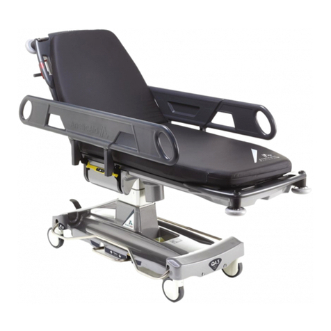
Anetic Aid QA3 21110 User manual

Document No. 992012. Issue 19 –24.10.22

Document No. 992012. Issue 19 –24.10.22

Contents Page
Document No. 992012. Issue 19 –24.10.22
Introduction
1. Introduction . . . . . . . . 1
1.1. Warnings & Cautions . . . . . . 1
1.2. Intended Use & Contraindications . . . . . 1
1.3. Device Classification . . . . . . 2
1.4. Serial Number Label . . . . . . 2
1.5. Putting the Stretcher into Service . . . . . 2
1.6. Abridged Summary of Warnings and Cautions . . . 2
2. Product Specifications . . . . . . . 4
3. Patient Stretcher Product Functions . . . . . 7
4. Emergency Stretcher Product Functions . . . . . 8
5. DRIVE Assist Product Functions . . . . . . 9
6. Powered Stretcher Product Functions . . . . . 10
7. Ophthalmic Stretcher Product Functions . . . . . 11
Manual Functions
8. Introduction to Manual Functions . . . . . 12
9. Height Adjustment . . . . . . . 12
10. Using the Brakes . . . . . . . 12
11. Using the Steering Pedal , activates 5th Wheel . . . . 12
12. Using the Side Rails . . . . . . . 12
13. Using the Backrest . . . . . . . 13
14. Using the Trendelenburg Function . . . . . 13
15. Using the Fold-away Pushing Handles . . . . . 13
16. Using the Transfusion Pole . . . . . . 14
17. Additional Features of an Emergency Stretcher . . . . 15
18. Using the Dual-articulating Head Positioner (QA3 Ophthalmic Stretcher only) 16
19. Using the Flexible Oxygen Delivery Bar Clamp . . . . 16
DRIVE Assist Function
20. Introduction to DRIVE Assist . . . . . . 17
21. Switching on DRIVE Assist . . . . . . 17
22. DRIVE Assist Handle Calibration . . . . . . 18
23. Using DRIVE Assist . . . . . . . 18
24. DRIVE Assist Handle Deactivation and Automatic Switch Off . . 19
25. Battery Charge Level Indication, Battery Charging & Maintenance . 19
26. Using DRIVE Assist with no Battery Power . . . . 19
27. DRIVE Assist Wheel Braking . . . . . . 19
Powered Functions
28. Introduction to Powered Functions . . . . . 21
29. Switching on Powered Functions . . . . . 22
30. Using Powered Functions . . . . . . 22
31. Using the Powered Height Adjustment . . . . . 22
32. Using the Powered Backrest Adjustment & Manual Over-ride Release Lever 22
33. Using the Powered KneeFlex Adjustment . . . . 22
34. Using the Combined Powered Backrest & KneeFlex Adjustment . 22
35. Using the CPR Position Button . . . . . . 22
36. Using the Emergency Stop Button . . . . . 23
37. X-ray Cassette Detection Sensor . . . . . . 23
38. Battery Charge Level Indication, Battery Charging & Maintenance . 23
Common Product Information
39. Patient Weight Limit . . . . . . . 24
40. K8 Pressure Care Mattress . . . . . . 24
41. Fitting a Replacement Mattress Cover . . . . . 25
42. Cleaning and Disinfecting . . . . . . 25
43. Product Warranty . . . . . . . 26
Contents Page
Document No. 992012. Issue 19 –24.10.22
44. Product Maintenance . . . . . . . 26
45. Label Identification . . . . . . . 27
Product Accessories
46. Product Accessories . . . . . . . 30
47. Using the Optional Monitor Shelf with Removable Refreshment Tray . 30
(catalogue no. 21152)
48. Using an Optional Loose Transfusion Pole (catalogue no. 21161) . 32
49. Using the Optional Storage Box (catalogue no. 21191) . . . 32
Quick Debugging Guide for DRIVE Assist & Powered Functions
50. Quick Debugging Guide for DRIVE Assist . . . . . 33
51. Quick Debugging Guide for Powered Functions . . . . 33
Quick Start Guide for DRIVE Assist (inside back page) . . . 34

Introduction
Document No. 992012. Issue 19 –24.10.22 Page 1
1. Introduction
These instructions are intended to assist you with the operation of the QA3 Patient
Stretcher series; it is important that they are read thoroughly before using the
equipment. The device will be adversely affected and its life expectancy reduced if the
following instructions are not observed. The QA3 Patient Stretcher series and product
variants are;
Code 21110 –QA3 Patient Stretcher
Code 21112 –QA3 DRIVE Patient Stretcher
Code 21114 –QA3 DRIVE Powered Patient Stretcher
Code 21116 –QA3 Powered Patient Stretcher
Code 21120 –QA3 Emergency Stretcher
Code 21122 –QA3 DRIVE Emergency Stretcher
Code 21124 –QA3 DRIVE Powered Emergency Stretcher
Code 21126 –QA3 Powered Emergency Stretcher
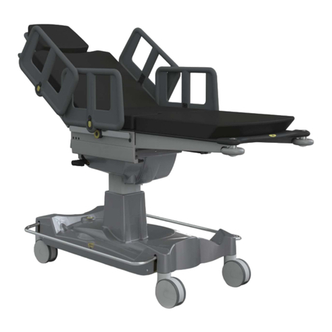
Code 21118 –QA3 Ophthalmic Stretcher
It is also important to check the stretcher before use to ensure there is no loss or change
in performance; ensure that all stretcher functions operate to their full range of
movement and that all components disengage, re-engage and lock correctly. We
recommend that the stretcher is visually inspected for any loose or damaged parts,
foreign bodies caught in the castors, and hydraulic fluid leakage.
NOTE:
If the stretcher is damaged or faulty it must be taken out of use with
immediate effect and the fault reported to Anetic Aid, your authorised dealer
or maintenance department. The stretcher must not be used until the damage
or fault has been repaired.
1.1. Warnings & Cautions
Various warnings and cautions are made throughout these operating instructions.
A WARNING is given when the personal safety of the patient or user may be
affected and when disregarding this information could result in injury.
A CAUTION is given when special instructions must be followed. Disregarding
this information could result in permanent damage being caused to the
stretcher.
1.2. Intended Use & Contraindications
The device’s intended use is as a method of transporting a patient to and from and in a
theatre, clinical or emergency medical department environment, being used for
examination, intubation, radiography and recovery of a patient following anaesthesia.
CONTRAINDICATIONS:
The stretcher is not compatible with hospital bed/stretcher washers.
The stretcher must not be used near magnetic resonance imaging (MRI) machines, or
any machines generating a large magnetic field.
Do not use the stretcher for transporting patients in a moving vehicle.
The stretcher should not be used outside; it may be damaged by pushing it across
rough or uneven ground.

Introduction
Document No. 992012. Issue 19 –24.10.22 Page 2
1.3. Device Classification
The device referenced in this document is CE marked and has been classified as a Class 1
Medical Device under the scope of both the Medical Devices Directive 93/42/EEC and the
Medical Device Regulation 2017/745.
1.4. Serial Number Label
The serial number label is located on the base cover moulding; see Fig. 2.
1.5. Putting the Stretcher into Service
Care should be taken when removing packaging, avoid the use of sharp implements
wherever possible.
It is important that the stretcher is working properly, fully charged (if applicable to the
model, see Section 24. Battery Charge Level Indication, Battery Charging &
Maintenance), cleaned and disinfected before it is put into service. Use this manual to
check all the functions and refer to section 40. Cleaning and Disinfecting the Stretcher.
The stretcher should only be used, for its intended use, by suitably trained personnel
who have familiarised themselves with the functions of the stretcher. Our
representatives are available for on-site consultation or training and our head office
team will be pleased to answer any queries you may have.
1.6. Abridged Summary of Warnings and Cautions
In common with all medical devices of this nature there are inherent risks that the user
should be made aware of, including potential pinch points from moving parts. Whilst
every effort has been taken to eliminate these risks, care should be taken when using
the stretcher. It is important that the user familiarise themselves with all of the
warnings and cautions contained within this document.
If the stretcher is damaged or faulty it mustbe taken out of use with immediate
effect and the fault reported to Anetic Aid, your authorised dealer or maintenance
department. The stretcher must not be used until the damage or fault has been
repaired.
When leaving patients unattended the stretcher should be fully lowered to minimise
any risk of injury should the patient fall off the stretcher.
Always apply the brakes when a patient is getting on or off the stretcher, or when
transferring patients from the stretcher to another platform.
It is important to ensure that nothing impedes the side rail release lever from locking
correctly; ensure that the release lever remains visible at all times.
After raising the side rail, it is important to ensure that it has locked in position by
pushing down on the side rail; failure to ensure the side rail is properly locked could
result in injury to the patient.
If the side rail mounted IV pole is in use when either raising or lowering the side rail
it is important to check the infusion flow rate as the height of the infusion above the
patient will change by approximately 300mm (11.8”).
When the backrest is raised, the fold-away pushing handles can come in close
proximity to the patient’s head and care should be taken.
Syringe drivers (and similar devices) can be mounted to the IV pole if extreme care is
taken when lowering or lifting the side rail with additional weight attached.

Introduction
Document No. 992012. Issue 19 –24.10.22 Page 3
When folding the transfusion pole away ensure that it is fully retracted and returned
to its storage position within the side rail; failure to do this may cause the pole to get
caught on obstructions when pushing the stretcher.
Using the transfusion pole to either push or pull the stretcher may cause permanent
damage to the transfusion pole and the side rail.
Do not raise the backrest with the x-ray tray, x-ray cassette or digital plate across the
backrest hinge as damage may occur.
Do not use a stretcher bed push, or other mechanical means for propulsion of the
stretcher, on a stretcher fitted with DRIVE assist.
The maximum slope angle for DRIVE assist is 6°; exceeding this angle could result in
damage to the stretcher or the fabric of the building.
Ensure the mains charging lead is disconnected before attempting to move the
stretcher; failure to do so could result in damage to the stretcher or the fabric of the
building.
Do not stow the fold-away handles when driving, or whilst DRIVE assist is active.
Ensure the brakes are engaged before stowing the fold-away handles.
When leaving a patient unattended, always switch off the DRIVE assist function and
apply the brakes.
Do not release the stretcher down a slope and rely on the DRIVE wheel brake to
control the stretcher descent.
Ensure there is nothing to impede the raising or lowering of the patient platform,
backrest, or KneeFlex as this could result in damage to the equipment and/or injury
to the patient.
Incompatible mattresses can create hazards; only replace the mattress with a new
mattress supplied by Anetic Aid, or your authorised dealer, to ensure compatibility in
accordance with BS EN 60601-2-52:2010+A1:2015.
Disinfectant products are corrosive in nature; failure to properly wash and dry the
stretcher surfaces could leave a corrosive residue which may cause damage to the
stretcher.
Do not use concentrated bleaching disinfectant solutions, organic solvents, abrasive
powders or expose any part of the stretcher to excessive heat.

Product Specifications
Document No. 992012. Issue 19 –24.10.22 Page 4
2. Product Specifications
Fig. 1

Product Specifications
Document No. 992012. Issue 19 –24.10.22 Page 5
Key to Fig. 1
QA3 Patient Stretcher
(and build options)
QA3 Emergency Stretcher
(and build options)
Castor Diameter
Ø150mm
(5.9”)
Ø200mm
(7.9”)
Ø150mm
(5.9”)
Ø200mm
(7.9”)
NOTE: Ø150mm are the standard option, Ø200mm is a build option.
Height range (all stretchers):
A.
Minimum stretcher height
475mm
(18.7”)
520mm
(20.5”)
535mm
(21.1”)
580mm
(22.8”)
Maximum stretcher height
775mm
(30.5”)
820mm
(32.3”)
835mm
(32.9”)
880mm
(34.6”)
NOTE: Height is measured from the floor to the patient platform and does not include the
mattress.
Ground clearance under the stretcher base:
B.
Under the 5th wheel pedal
mechanism, head end
90mm
(3.5”)
90mm
(3.5”)
90mm
(3.5”)
90mm
(3.5”)
C.
Under the base frame, foot end
90mm
(3.5”)
135mm
(5.3”)
90mm
(3.5”)
135mm
(5.3”)
D.
Under the lift column
44mm
(1.7”)
90mm
(3.5”)
44mm
(1.7”)
90mm
(3.5”)
NOTE: The ground clearance figures quoted are general guidelines; as per Fig. 1 the
stretcher is compatible with hoists with leg heights up to 120mm on either castor option,
Ø150 or Ø200mm.
Mattress dimensions for QA3, <800> and Ophthalmic (OPH) stretchers:
E.
Mattress length
QA3
2025mm (79.7”)
<800>
OPH
2245mm (88.4”)
F.
Mattress width
QA3
700mm (27.6”)
<800>
800mm (31.5”)
OPH
700mm (27.6”)
G.
Mattress depth
QA3
90mm (3.5”)
<800>
105mm (4.1”)
OPH
90mm (3.5”)
NOTE: Refer to Section 39, ‘K8 Pressure Care Mattress’, for full specification details.
Stretcher length:
H.
Patient platform flat
QA3
2150mm (84.6”)
OPH
2275mm (89.6”)
I.
Backrest raised (70°)
1820mm (71.7”)
J.
Backrest (70°) & kneeFlex raised (30°)
1700mm (66.9”)
Stretcher widths:
K.
Side rails up
QA3
805mm (31.7”)
Side rails up
<800>
905mm (35.6”)
L.
Side rails down
QA3
735mm (28.9”)
Side rails down
<800>
795mm (31.3”)
Brakes off
QA3/800
735mm (28.9”)
M.
Width between side rails up
QA3
745mm (29.3”)
Width between side rails up
<800>
845mm (33.3”)
Backrest & kneeFlex articulations:
N.
Manual function backrest
0 - 90°
Powered function backrest
0 - 70°
O.
KneeFlex
0 - 30°
N/A
IV pole:
P.
Maximum height of pole
2110mm (83.1”)
2155mm (84.8”)
Maximum weight per hook
3kg (6.6lbs) or 3 Litres (101.4 fl oz.)
Safe working load (SWL)
6kg (13lb)
Trendelenburg:
Trendelenburg
12°
Reverse Trendelenburg
10°

Product Specifications
Document No. 992012. Issue 19 –24.10.22 Page 6
NOTE: Trendelenburg is a standard stretcher function, ‘Reverse Trendelenburg’ is an
optional function.
Patient weight limit and safe working load (SWL):
Maximum patient weight
320kg (705.5lbs)
Safe working load (SWL)
320kg (705.5lbs)
NOTE: Refer to Section 38, ‘Patient Weight Limit’, for more information about maximum
patient weight limit, safe working load and special precautions when handling heavy
patients.
Stretcher weights:
Code 21110 / 21120
128.0kg (282.2lbs)
148.0kg (326.3lbs)
Code 21112 / 21122
143.5kg (316.4lbs)
157.0kg (346.1lbs)
Code 21114 / 21124
148.0kg (326.3lbs)
162.5kg (358.3lbs)
Code 21116 / 21126 / 21118
141.0kg (310.9lbs)
154.5kg (340.6lbs)
NOTE: Fitting the Ø200mm castor option adds 2kg to the total stretcher weight.
DRIVE Assist function:
DRIVE Assist range
> 20km (12.4 miles)
NOTE: This figure is a guide only, and will vary depending upon a number of conditions,
i.e.; patient weights, the number and severity of inclines, battery age, etc.
Maximum slope angle
6°
DRIVE handle deactivation
3 minutes
System switch off
30 minutes
Battery type, mains charging input, charging times:
Battery specification
NiMH, 9Ah 24V
Mains charging input
100-240V~, 50-60Hz. T2.5A 250V 20mm
Full charge time from flat
5hrs
Partial charge time
30 minutes per 10% of the full charge
NOTE: The charging figures quoted are dependent upon the age and condition of the
battery, and are guidelines only.
Electrical classification:
Class I
EMC compatibility:
IEC 60601-1-2:2015
IP rating:
IPX4
Environmental conditions:
Temperature:
Operation
10°C to 50°C
Storage & Transport
-20°C to 50°C
Relative humidity:
Operation
30% to 75%
Storage & Transport
10% to 75%
Atmospheric pressure:
Operation
70kPa to 106kPa
Storage & Transport
50kPa to 106kPa
Environmental regulatory information; WEEE, waste batteries, etc.:
For the latest information about Anetic Aid’s environmental policy, WEEE policy, and the
safe disposal of this product, please refer to our website.
NOTE: All dimensions quoted are subject to the following tolerances; angles ±5°, lengths and
widths ±25mm, depths ±10mm. Anetic Aid reserves the right to change specifications without
notice.

Product Functions
Document No. 992012. Issue 19 –24.10.22 Page 7
3. Patient Stretcher Product Functions (21110)
Key to Fig. 2
1.
Backrest Actuation Lever.
2.
Trendelenburg Actuation Lever.
3.
Steering Pedal (activates 5th wheel).
4.
Brake Pedal.
5.
Raise and Lower Pedal.
6.
Side Rail.
7.
Side Rail Release Lever.
8.
Fixed Transfusion Pole.
9.
Fold-away Pushing Handles.
10.
Fixed Pushing Handles.
11.
Oxygen Cylinder Mounting Trough (accommodates F, ZX, D, E & CD size's)
NOTE: A CD cylinder support bracket is available (catalogue no. 53556).
12.
Storage Recess.
13.
Serial Number Label.

Product Functions
Document No. 992012. Issue 19 –24.10.22 Page 8
4. Emergency Stretcher Product Functions (21120, 21122, 21124 and 21126)
Key to Fig. 3 - See Fig. 2 Patient Stretcher specification for standard features.
14.
Additional Fixed Transfusion Pole.
15.
‘V’ Mounting for 1 Litre Suction Canister.
16.
X-Ray Platform.

Product Functions
Document No. 992012. Issue 19 –24.10.22 Page 9
5. DRIVE Assist Product Functions (21112, 21114, 21122 and 21124)
Key to Fig. 4 - See Fig. 2 Patient Stretcher specification for standard features.
17.
Fold-away DRIVE assist Pushing Handles.
18.
Fixed DRIVE assist Pushing Handles.
19.
Charging Socket.
20.
Head End User Interface, see Fig. 13 in Section 19 for more details.
Used on DRIVE Patient Stretcher (21112), DRIVE Emergency Stretcher (21122).
21.
Head End User Interface, see Fig. 14 in Section 19 for more details.
Used on DRIVE Powered Patient Stretcher (21114), DRIVE Powered Emergency
Stretcher (21124). NOTE: This interface has a CPR Position Button for use with
Powered Function Stretchers only.
22.
Storage hooks for the mains power lead.

Product Functions
Document No. 992012. Issue 19 –24.10.22 Page 10
6. Powered Product Functions (21114, 21116, 21124 and 21126)
Key to Fig. 5 - See Fig. 2 Patient Stretcher specification for standard features.
23.
Head End User Interface, see Fig. 14 in Section 19 for more details.
Used on DRIVE Powered Patient Stretcher (21114), DRIVE Powered Emergency
Stretcher (21124).
24.
Foot End User Interface, see Fig. 15 in Section 27 for more details.
Used on Powered Patient Stretcher (21116), DRIVE Powered Patient Stretcher
(21114).
Powered functions: Height, Backrest, KneeFlex and CPR Position Button.
25.
Foot End User Interface, see Fig. 16 in Section 27 for more details.
Used on Powered Emergency Stretcher (21126), DRIVE Powered Emergency
Stretcher (21124), Ophthalmic Stretcher (21118).
Powered functions: Height, Backrest and CPR Position Button.
26.
Emergency stop button.

Product Functions
Document No. 992012. Issue 19 –24.10.22 Page 11
7. Ophthalmic Product Functions (21118)
Key to Fig.6 - See Fig. 2 Patient Stretcher specification for standard features, and See
Fig. 5 Powered Product specification for powered functions.
2.
Trendelenburg Actuation Levers; there are two levers, one on the patient left
hand side of the trolley, and one on the patient right hand side.
27.
Dual-articulating Head Positioner head section; see Section 18, ‘Using the Dual-
articulating Head Positioner’.
28.
Head section release lever.

Manual Functions
Document No. 992012. Issue 19 –24.10.22 Page 12
8. Introduction to Manual Functions
This section of the document gives a description of product functions that are manually
operated, and how to use them. Some of the manual functions are common across the
product range, and are relevant to DRIVE, DRIVE Powered and Powered Stretchers.
9. Height Adjustment
The height of the patient platform is adjusted by using either of the raise and lower
pedals (item 5, Fig.2). Pumping either pedal will raise the patient platform, lifting either
pedal will lower the patient platform.
WARNING: Ensure there is nothing to impede the raising or lowering of the
patient platform as this could result in damage to the equipment and/or injury
to the patient.
WARNING: When leaving patients unattended the stretcher should be fully
lowered to minimise any risk of injury should the patient fall off the stretcher.
10. Using the Brakes
All four castors are simultaneously braked by depressing either of the brake pedals at
any point along the length of the pedal (item 4, Fig.2). The brakes are disengaged by
lifting either pedal.
WARNING: Always apply the brakes when leaving a patient unattended, a
patient is getting on or off the stretcher, or transferring patients from the
stretcher to another platform.
11. Using the Steering Pedal, activates 5th wheel
The stretcher can be manoeuvred more easily by engaging the 5th wheel steering
mechanism (item 3, Fig.2). NOTE: This is a non-powered 5th wheel, see Section 19.
‘Introduction to DRIVE Assist’, for details about the powered DRIVE assist wheel option.
The mechanism is engaged, and disengaged, by pressing down on the steering pedal. To
move the stretcher sideways disengage the 5th wheel.
CAUTION: Applying the steering pedal with excessive force, i.e. by standing on
it, may cause permanent damage to the mechanism.
12. Using the Side Rails
The stretcher is fitted with two side rails that can be individually raised and lowered
(item 6, Fig. 2). Lower the side rail by pulling up on the side rail release lever (item 7,
Fig. 2) and pushing the side rail down. Raise the side rail by gripping it and pulling up
firmly to its full height; the release lever will make an audible ‘CLICK’ when engaged.
The side rail will now be locked into position.
WARNING: It is important to ensure that nothing impedes the side rail release
lever from locking correctly; ensure that the release lever remains visible at all
times.
WARNING: After raising the side rail it is important to ensure that the release
lever has properly locked in position by pushing down firmly on the side rail.
Failure to ensure the side rail is properly locked could result in injury to the
patient.
CAUTION: If the side rail mounted IV pole is in use when either raising or
lowering the side rail it is important to check the infusion flow rate as the
height of the infusion above the patient will change by approximately 30 cm.
NOTES:
The side rails are designed to prevent a patient inadvertently rolling off the
stretcher; they are not intended to restrain the patient.

Manual Functions
Document No. 992012. Issue 19 –24.10.22 Page 13
NOTES:
When the IV pole is in use, the weight of the side rail is increased and the side
rail may lower more quickly. Keep a firm grip on the side rail as it lowers to
control its movement; see Section 16, ‘Using the Transfusion Pole’, for details
on the maximum weight for the IV pole.
13. Using the Backrest
The backrest is moved up or down by pulling up on the backrest actuation lever (item 1,
Fig. 2) whilst keeping a firm grip on the pushing handle to control the movement.
NOTE:
It is important to note that the backrest provides only minimal lift assistance;
the patient should be assisted into a sitting position as the backrest is
articulated up.
CAUTION: When the backrest is raised the fold-away pushing handles can come
in close proximity to the patient’s head and care should be taken.
14. Using the Trendelenburg Function
The patient platform can be moved into a Trendelenburg, or Reverse Trendelenburg,
position by pulling up on the Trendelenburg actuation lever (item 2, Fig. 2) whilst
maintaining a firm grip on the platform handle to control the movement. The tilt
speed can be controlled by the gradual squeezing of the actuation lever rather than
pulling it fully.
NOTE:
Trendelenburg is a standard stretcher function, Reverse Trendelenburg is an
optional function.
WARNING: When handling heavy patients, extreme care should be taken when
attempting to tilt the platform head down and assistance should be sought to
take the weight of the platform when released; failure to do so could result in
injury to the user.
15. Using the Fold-away Pushing Handles
The stretcher is fitted with two fold-away pushing handles at the head end of the
stretcher (item 9, Fig. 2).
NOTE:
It is an option to have fold-away pushing handles fitted to the foot end of the
stretcher (catalogue no. 21155).
As illustrated in Fig. 6 each pushing handle is swivelled out (A), up (B), and then allowed
to drop down into the mounting socket ready for use (C). The handles should be folded
away when not in use.
CAUTION: When the backrest is raised, the fold-away pushing handles can
come in close proximity to the patient’s head and care should be taken.

Manual Functions
Document No. 992012. Issue 19 –24.10.22 Page 14
16. Using the Transfusion Pole
The Patient Stretcher is supplied with one fixed transfusion pole fitted into the patient’s
left hand side rail (item 8, Fig. 2). The Emergency Stretcher is fitted with two fixed
transfusion poles, one on each side rail.
To use the transfusion pole, as illustrated in Fig. 7; pull the transfusion pole away from
the side rail storage position (A), articulate the transfusion pole up 90° to the vertical
position (B), and allow the transfusion pole to drop down and engage into the
mounting socket (C).
To adjust the height of the transfusion pole, as illustrated in Fig. 8a; grasp the locking
mechanism (A) and using your thumb, lift the mechanism to release the lock and move
the pole up or down to the required height (B); release the mechanism to lock the pole
in position.
CAUTION: When adjusting the height of the pole use two hands; one to adjust
the height of the inner pole and hooks, and the other to hold the outer pole
to ensure that it remains fully engaged in the mounting socket.
The transfusion pole is fitted with two spring-loaded hooks that are designed to return
to their original upright position when not in use. Swivel one or both hooks outwards
(C) to hang the IV bags, as illustrated in Fig. 8b.
NOTE:
The maximum weight limit per IV hook is 3kg (6.6lbs) or 3 litres (101.4 fl oz.),
and the recommended safe working load for the IV pole is 6kg (13.2lbs).
Syringe drivers (and similar devices) can be mounted to the IV pole if the
following CAUTION is observed.
CAUTION: Syringe drivers (and similar devices) can be mounted to the IV pole if
extreme care is taken when lowering or lifting the side rail with additional
weight attached.

Manual Functions
Document No. 992012. Issue 19 –24.10.22 Page 15
CAUTION: When folding the transfusion pole away ensure that it is fully
retracted and returned to its storage position within the side rail; failure to do
this may cause the pole to get caught on obstructions when pushing the
stretcher.
CAUTION: Using the transfusion pole to either push or pull the stretcher may
cause permanent damage to the transfusion pole and the side rail.
CAUTION: If the side rail mounted IV pole is in use when either raising or
lowering the side rail it is important to check the infusion flow rate as the
height of the infusion above the patient will change by approximately 300mm
(11.8”).
17. Additional Features of an Emergency Stretcher
The QA3 v3.0 Emergency Stretcher is specially designed to accommodate the needs of
accident and emergency departments and includes: a raised x-ray radiolucent platform
(item 16, Fig. 3) suitable for analogue and digital direct radiography and computed
radiography, an additional fixed transfusion pole fitted into the patient’s right hand
side rail (item 14, Fig. 3) and a suction system mounting ‘V’ bracket (item 15, Fig. 3).
To improve access for cleaning beneath the x-ray platform both the backrest and leg
sections can be articulated upwards for easy access to the patient platform surface.
NOTES:
All known original equipment manufacturers mobile imaging generators, and
floor or ceiling mounted fixed imaging generators (which offer horizontal
and vertical tracking), including U-armed, are compatible.
The maximum detector, or cassette, dimension that can be accommodated is
W520mm x L610mm x H48mm (W20.5” x L24.0” x H1.9”); this includes any
carrier or protective case.
Analogue and digital direct detectors are loaded beneath the x-ray platform and
between the supporting posts; see Fig. 9 for the relevant dimensions. Alternatively, the
detectors can be loaded on the optional x-ray tray, and then positioned anywhere
below the platform.
CAUTION: Do not raise the backrest with the x-ray tray, x-ray cassette or digital
plate across the backrest hinge as damage may occur.

Manual Functions
Document No. 992012. Issue 19 –24.10.22 Page 16
18. Using the Dual-articulating Head Positioner (QA3 Ophthalmic Trolley only)
The stretcher is designed to allow for different head section options to be fitted; the
image below shows the ‘Dual-articulating Head Positioner’ (see Section 45. Product
Accessories, for optional head sections). To remove the head section, lift the release
handle Fig. 10 (C), then lower and remove the head section from the support bracket.
The head positioner articulates on 2 axes, (A) and (B). Pulling on lever (A) allows the
head piece of the positioner to articulate on axis (A). Pulling on lever (B) allows the neck
piece to articulate on axis (B); see Fig. 10. Using the levers in combination the head
positioner can be elevated up and in towards the body section mattress as shown in Fig.
11a and 11b.e
NOTE:
The maximum weight limit for the dual-articulating head section is 25kg.
CAUTION: When releasing the levers it is important to support the weight
of the patients head. Failure to do so could result in injury to the patient.
19. Using the Flexible Oxygen Delivery Bar Clamp
The Flexible Oxygen Delivery Bar Clamp, Fig. 12 (A), is used to secure the Flexible
Oxygen Delivery Bar and Drape Screen (B) to either siderail. The Flexible Oxygen
Delivery Bar and Drape Screen is intended to support the patient drape, and deliver a
continuous flow of oxygen beneath the drape when connect to an oxygen supply.
The clamp is placed into the elliptical opening of the siderail and rotated so that flat
plate sits against the siderail moulding, as illustrated below. The oxygen delivery bar is
inserted into the opening of the clamp (C), and secured with the hand wheel (D); the
height of the oxygen delivery bar can be adjusted to suit. The oxygen supply is
connected to the inlet nozzle (E).
This manual suits for next models
6
Table of contents
Other Anetic Aid Medical Equipment manuals

Anetic Aid
Anetic Aid QA4 21359 User manual

Anetic Aid
Anetic Aid 10233 User manual

Anetic Aid
Anetic Aid QA3 User manual

Anetic Aid
Anetic Aid QA4 User manual

Anetic Aid
Anetic Aid AT4 User manual

Anetic Aid
Anetic Aid QA4 User manual

Anetic Aid
Anetic Aid 21380 User manual

Anetic Aid
Anetic Aid QA4 User manual

Anetic Aid
Anetic Aid QA3 User manual