Tormax iMotion 2202.A User manual

Brokelandsheia, 4993 Sundebru, Tlf + 47 37119950 Fax + 47 37119951
E-mail: post@picomed.no Foretaksnummer 962 211 631 MVA
Omgivelseskontroll
Dokumentasjon for Dørautomatikk
Picomatic 2202
Picomatic 2301
Picomatic 2302
Picomatic 2401
(Tormax 2202, 2301, 2302 og 2401 for
omgivelseskontroll)

T-1321 e 6.12.13
Translation of the original
instructions for use
Instructions for Use
For Automatic Sliding Doors with Drive
iMotion®2202 Sliding Door Drive
iMotion®2202.A Sliding Door Drive
iMotion®2301/2301.IP65 Sliding Door Drive
iMotion®2302 Sliding Door Drive
iMotion®2401/2401.IP65 Sliding Door Drive

2Instructions for Use iMotion 2202 / 2301/ 2302 / 2401 T-1321 e
First edition: 10.08, Update: 3.11, 2.12, 12.13
We reserve the right to make technical changes.
Printed on environmentally friendly paper bleached without the use of chlorine.
Landert Motoren AG and Landert GmbH are certified to ISO 9001.
Contents
1 General Information 3
1.1 Target Groups 3
1.2 Storage and dissemination of the manual 3
1.3 Area of Application 3
1.4 Explanation of the Symbols 4
1.5 Technical Data 4
2 Safety 5
2.1 Responsibilities 5
2.2 Use for the Purpose Intended 5
2.3 Pre-conditions for the Operation of the System 5
2.4 Hazards and Risks 5
2.5 Checks 6
2.6 Taking the System out of Service in the Event of a Fault 6
2.7 Disposal 7
3 Product Description 8
3.1 System Overview 8
3.2 System Function 9
3.3 Operating Modes 10
4 Operation 11
4.1 Commissioning 11
4.2 Operation with the TORMAX User Interface 11
4.3 Operation with an Operating Mode Switch 12
4.4 Operation on Power Failure 12
5 Procedure in the Event of a Fault 13
6 Maintenance 14
6.1 Cleaning 14
6.2 Functional Checks 14
6.3 Maintenance and Testing 14
7 Appendix 15
7.1 Fault Table 15
7.2 Check-list for Functional Checks 17
Declaration of Conformity 18

Instructions for Use iMotion 2202 / 2301/ 2302 / 2401 T-1321 e 3
1 General Information
1.1 Target Groups
• Operatoroftheautomaticdoor.Theoperatoristhepersonresponsiblefortheoperationandmain-
tenance of the system.
• Personsinstructedbytheoperatortocarryoutcertainduties,forexampletheservicingandmain-
tenance of the automatic sliding door.
1.2 Storage and forwarding of the manual
• Storetheinstructionsforuseinthevicinityof theautomaticdoorsystem.
• Ifthemanualhasbecomeillegibleduetoconstantusage,reordertheinstructions.
• Whenthedoorsystemistransferredorresaledtoathirdparty,passthefollowingdocumentstothe
new owner:
– This instructions for use
– Documentation concerning modification and repair work
– Proof of the regular examinations System test book T-879
1.3 Area of Application
Product name, door system: Automatic sliding door
Product name, door drive: iMotion®2202 Sliding Door Drive
iMotion®2202.A Sliding Door Drive
iMotion®2301 / 2301.IP65 Sliding Door Drive
iMotion®2302 Sliding Door Drive
iMotion®2401 / 2401.IP65 Sliding Door Drive
Serial number: ………………………………………
Identification plate
(example)
The identification plate
with the serial number is
attached to the header
section.

4Instructions for Use iMotion 2202 / 2301/ 2302 / 2401 T-1321 e
<
1.4 Explanation of the Symbols
Warning (signal word)
Source of hazard (designates a possibly hazardous situation)
Possible consequences of non-observance
•Measuresforavertingdanger.
Text which is highlighted in grey MUST be observed to ensure that the system operates perfectly.
Failure to observe these sections can cause damage to equipment.
Functions marked with this symbol are the factory setting. However, they can be reprogrammed
by a specialist.
Optional components which are not present in all systems.
1.5 Technical Data
Drive type Electro-mechanical sliding door drive with direct drive (iMotion 2301,
2302, 2401) using an AC permanent magnet synchronous motor
Control system Control unit MCU32
Mains connection 1 x 230 VAC, 50 – 60 Hz, 10 A / 1 x 115 VAC, 50 – 60 Hz, 15 A
Power consumption iMotion 2202, 2301, 2302: max. 190 W
iMotion 2301.IP65: max. 240 W
iMotion 2401: max. 310 W
iMotion 2401.IP65: max. 350 W
Sensor supply iMotion 2202, 2301, 2302: 24 V DC (+0,5 –1,5 V) 0,75 A
in battery operation min. 16,5 V
iMotion 2401: 24 V DC (+0,5 –1,5 V) 1,5 A
in battery operation min. 16,5 V
iMotion 2301.IP65: 0,75 A
iMotion 2401.IP65: 1,5 A to +30 °C, 1,0 A to +50 °C
Protective class, drive IP 22 ( IP65 for iMotion 2301.IP65 and 2401.IP65)
Fusible 5 AT
Ambient temperature –20 °C to +50 °C
Noise emission level < 70 db (A)

Instructions for Use iMotion 2202 / 2301/ 2302 / 2401 T-1321 e 5
2 Safety
2.1 Responsibilities
For instructing the operator: A specialist from a TORMAX sales partner
For operating the system: The operator or a person instructed by the operator
For maintenance and function control: The operator or a person instructed by the operator
For annual testing and approval: A specialist authorised by the manufacturer
Specialists are persons who have adequate knowledge in the field of power-operated doors as a result
of their specialist training and experience and who are so familiar with the relevant health and safety
regulations, guide-lines and generally recognised codes of practice that they are able to assess the
condition of power-operated doors with regard to the safety of their operation.
Maintenance of electrical parts must be carried out by a trained electrician.
2.2 Use for the Purpose Intended
The automatic sliding door is intended exclusively for use in dry premises in areas used as a pedes-
trian thoroughfare. The manufacturer will not accept any liability whatsoever for loss or damage caused
by improper use, failure to comply with the maintenance specification (see section 6) or unauthorised
modification of the system.
2.3 Pre-conditions for the Operation of the System
The door system was designed, installed and checked for functionality and safety by specialists prior
to hand-over to the operator. The company responsible for the system’s installation instructed the op-
erator on the system’s use and maintenance as well dangers associated with the system operation.
The operator has confirmed this by his signature in the system test book T-879.
The provisions imposed by law, health and safety and occupational health regulations for the avoidance
of accidents and the protection of the environment which are generally applicable in the country in
which the system is operated supplement the instructions for use.
• Readtheinstructionsforusecarefullybeforecommissioningtheautomaticslidingdoor.
• Onlyusethesystemwhenitisinperfectworkingorder.Theoperatingconditions,inspection
and maintenance intervals stipulated by the manufacturer must be observed (section 6).
• Safetyfacilities(e.g.sensortechnology,manualunlocking)mustnotberemovedordisabled.
• Arrangetohaveanyfaultsrectiedimmediatelybyaspecialist.
2.4 Hazards and Risks
Depending on the system design and equipment, there is a residual risk of crushing, entanglement and
collision in the movement area of the door leaves – albeit with restricted force.

6Instructions for Use iMotion 2202 / 2301/ 2302 / 2401 T-1321 e
Warning
Danger through moving parts:
– in the area of all closing edges
– in the gap for suspending the door in the cladding
– when objects such as, for example, display shelves are erected in the direct proximity of
the moving part of the door leaf.
Risk of injury
• Donotallowchildrentoplayinthedirectproximityoftheautomaticdoor.
• Childrenmaynotoperatetheexistingoperatingunits.
Warning
Hazards can arise due to deliberate damage, incorrect installation, defec-
tive sensors or sensors which are longer properly adjusted, sharp edges,
incorrectly mounted and defective casing or missing covers.
• Dangerforbodyandlife,dangerofinjury
• Havesystemrepairedbyaqualiedperson
2.5 Checks
The regular checks and examinations set out in Chapter 6 must be carried out as instructed by the
manufacturer. The manufacturer recommends that a maintenance contract be concluded in order to
operate the system safely and to maintain its value for as long as possible.
2.6 Taking the System out of Service in the Event of a Fault
If there is a fault the automatic door may only be taken out of service by a specialist, the operator or a
person who is instructed to do so by the operator. This must be done on all occasions on which the
safety of persons could be compromised.
• Disconnectthesystemfromthepowersupply.
• Selectoperatingmode“P”ifthesystemisneverthelesstocontinuetobeoperatedusingtheinternal
emergency power supply (see section 3.3 for operating modes).
• Openthedoormanuallyandleaveopenif itisinstalledinanescaperoute.
See section 7 for rectification of faults.

Instructions for Use iMotion 2202 / 2301/ 2302 / 2401 T-1321 e 7
2.7 Disposal
This system must be properly dismantled at the end of its working life. Its disposal must comply with
national regulations. We recommend that you contact a specialist disposal company.
Warning
Aggressive acids
Risk of injury if you dismantle the battery module.
• Disposeofbatteriesproperly.
Warning
Broken glass
Risk of injury when dismantling the door leaves.
• Takecarewhentransportingthedoorleaves.

8Instructions for Use iMotion 2202 / 2301/ 2302 / 2401 T-1321 e
T1321_4e
3c 3a 3a
HK
inside outside
NK NK
5a, 7a
3d
3c
3d
3b 3b
1
4a
4c
8b
7c
7b 6a
6b
2a 4d 4b
8c
7d 7d
2a
8a
2b
3 Product Description
3.1 System Overview
1 Drive Cladding
Motor unit
MCU32 control system with monitoring system, power limitation and perma-
nent diagnosis
Guide system with noise-absorbent guide rail
2Drive accessories u£Lock with
a) £internal manual activation £in the cladding £on the wall
b) £external manual activation
£Emergency power supply via the battery unit
£Mechanical emergency opening
3 Door leaves a) Moving leaves with main closing edge (HK) and secondary closing edge (NK)
b) Moving leaves with floor guide
c) £Side part u
d) £Protection leaves uas protection for the secondary closing edge
4Operating controls a) £iMotion user interface with 6 operating modes and fault display
b) £Operating mode switch with 3 positions.
c) £Lock for the user interface
d) £Remote control of operating modes
5Internal activators a) With automatic activation b) With manual activation
£Radar with/without direction recognition £Push button
£IR motion detector £Contact-free button
6External activators a) With automatic activation b) With manual activation
£Radar with/without direction recognition £Key switch
£IR motion detector £Card reader
£Remote control
7Safety sensors a) £Presence sensor: main closing edge protection
b) £Presence sensor, external: main closing edge protection
c) £Safety beams
d) £Presence sensors: secondary closing edge protection
8Emergency systems a) £Power switch / fuse
b) £Emergency on/off switch
c) £Fire alarm system
9Output message u£Bell / gong £Light / ventilation £Door locked
£Door status ………………
£Depending on the system’s equipment

Instructions for Use iMotion 2202 / 2301/ 2302 / 2401 T-1321 e 9
T1321_12
3.2 System Function
It is the responsibility of the system operator to ensure that the automatic sliding door can be
freely used at all times and particularly that access to the sliding door is not blocked.
Automatic Door Operation with Sensors
When operating automatically (AUTOMATIC operating mode) the door is automatically opened from
both sides by sensors when a person approaches.
A key switch uor card reader unormally allows access from outside when the door is in operating
mode EXIT or OFF. The door unlocks, opens and closes again as soon as no further sensors are ac-
tivated after a hold-open time which is set separately.
The sensors for the door opening and the maintained opening of the door are arranged and adjusted
in such a way that the door opens promptly and remains open as long as a person is within the operat-
ing range of the door leaves. The door can close nevertheless but only after an attendance time of
approx. > 1 minute.
The reduced closing speed which is set by the installer and is adjusted in line with the door weight,
combined with a force of < 150 N prevents the impact of the moving leaves on a person from being too
severe. The obstruction is also detected by the control system and the door automatically reverses.
Traffic Control
Movement through the door can be allowed in only one direction if desired (operating mode EXIT) or
completely blocked (operating mode OFF).
In order to protect against environmental influences (wind/cold/heat) the door can be operated in op-
erating mode AUTOMATIC 2 with a restricted opening width which is not less than the required escape
route width.
Automatic System Monitoring
The control system monitors the safety sensors by a cycle of active tests. The control system also
conducts continuous internal system tests. If a safety-related component should fail, the system auto-
matically switches into a safe condition. At the same time the fault number is displayed on the user
interface.Youcanndfurtherinformationonthissubjectinsection5“ProcedureintheEventof Faults”.
Electro-mechanical Lock u
The system can be locked in the closed position by means of an electro-mechanical lock u or held in
the closed position by a holding magnet uwhen in operating mode OFF and, if required, in other op-
erating modes (e.g. EXIT).
The locking process is monitored. Thus any fault of the locking operation can be immediately displayed
ontheuserinterface.Seesection5“ProcedureintheEventofFaults”fordetails.
In the event of a power failure the locks can also be directly activated by the optional manual facility.
Operation in the Event of a Power Failure
Depending on the equipment installed, the following functions are possible:
– Immediate emergency opening or closing by a mechanical energy store u.

10 Instructions for Use iMotion 2202 / 2301/ 2302 / 2401 T-1321 e
P
– Immediate unlocking (only if programmed by the installer).
– Continued operation of the system by means of a battery unit ufor a specific time with the doors
opening before the battery switches off. The door remains locked in operating mode OFF.
– Unlocking and opening of the door from outside by means of a key switch and the battery unit u.
3.3 Operating Modes
By using the TORMAX user interface uit is possible to operate the automatic door system in 6 operat-
ing modes and with status displays or to use a simple operating mode switch uto operate the door in
3 operating modes.
Operating Mode OFF
The internal and external sensors are disregarded. The door is maintained in the closed position either
by the motor or the holding magnet uand/or locked by the electro-mechanical lock u. Access is only
possible using the key switch u.
<The door can still be used for 5 seconds after selecting operating mode OFF. The door then locks
at the end of this period as soon as it is closed. The transition is signalled on the user interface by the
flashing display of operating mode OFF.
Operating Mode AUTOMATIC 1
The operating mode AUTOMATIC 1 is normally used during the day. The door opens automatically
(normally to its full opening width) to both sides by means of the internal and external sensors.
Operating Mode AUTOMATIC 2
Operating mode AUTOMATIC 2 is normally used during the day. The door opens automatically (nor-
mally with a reduced opening width) to both sides by means of the internal and external sensors.
<If required, the hold open time can be set by the installer for a different period to the one used in
AUTOMATIC 1.
Operating Mode EXIT
Operating mode EXIT is normally used for the period before the shop or office closes. The door will
only open automatically when activated by the internal sensor.
When the door opens the external sensor is also monitored for safety reasons.
The opening width is determined by previously selecting operating mode AUTOMATIC 1 or AUTOMATIC
2. The door can be automatically blocked using the holding magnet u.
Operating Mode OPEN
The door opens and remains open. The opening width is determined by previously selecting operating
mode AUTOMATIC 1 or AUTOMATIC 2.
Operating Mode Manual Operation
The door leaves can be freely moved. This operating mode can be used for cleaning the door leaves
and the floor guide or for temporarily shutting down the door. The system is reset after leaving this
operating mode.
Instructions for Use iMotion 2202 / 2301/ 2302 / 2401 T-1321 e 11
4 Operation
The automatic sliding door may only be operated by a specialist, the operator or a person instructed
by the operator.
4.1 Commissioning
Before switching on the mains power supply:
• Unlocktheoptionalmechanicaldoorlocke.g.oorlock.
• Checkthatthemovementareaof thedoorleavesisfreefromobjectse.g.umbrellastandsorvehicles.
• Checkthattheoorguide(particularlyif itiscontinuous)iscleanandnotblockedbyanything(e.g.
gravel or snow).
• SwitchonthemainspowersupplyandselectoperatingmodeAUTOMATIC1,forexample.
The first movement after switching the power on for the first time is slow and H61/ H62 is dis-
played. The control system is checking the door leaf’s travel distance and defining the end position.
The door is now ready for operation.
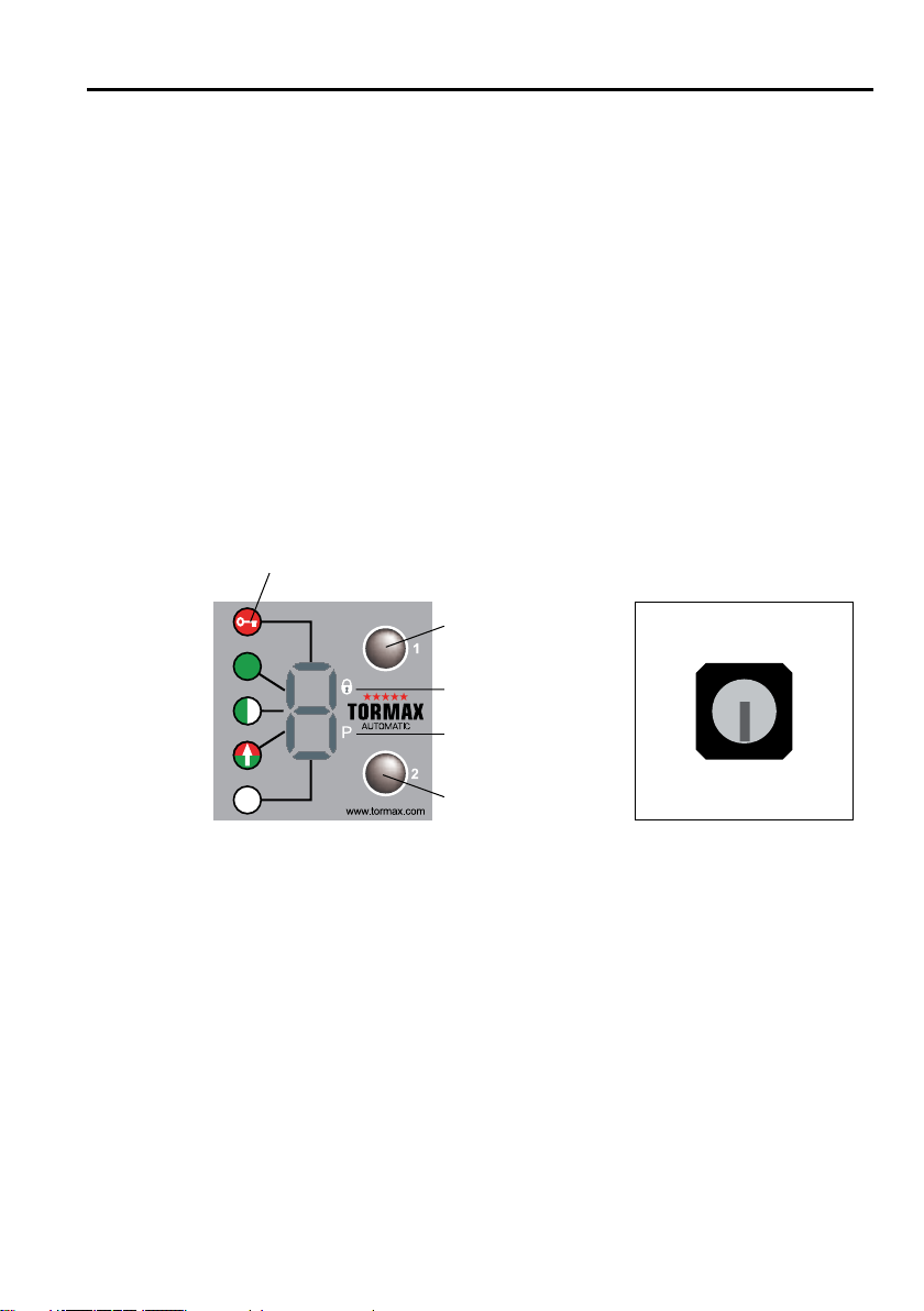
4.2 Operation with the TORMAX User Interface
TORMAX User Interface Lock ufor User Interface
Unlocking of operating unit
The operating unit can be protected against unauthorised access by way of the lock uor the code lock.
• Unlocklock=position0
or
• Entercode…/…/…usingoperatingunit.Standardcode=3/3/3.Thecodecanbedetermined
by the engineer.
Example with code 3 / 3 / 3. Press upper selection button 3 times, then press the lower selection but-
ton 3 times and the upper selection button within 15 s . In case of entering wrong code: Wait at least
5 s . After successfully entering the code, the operating unit will be released within 60 s. The type of
operation can be adjusted. Access will be automatically blocked again for 60 s after the button has
been pressed for the last time.
Selection of Operating Modes
• Pressselectorkeys1or2briey.Thecorrespondingoperatingmodesymbolisilluminated.
www.tormax.com
1
2
3
4
1
1
0
T1321_1e
OFF
AUTOMATIC 1
AUTOMATIC 2
OPEN
EXIT
Operating mode
symbols
Manual operation
Door electrically
locked
Selector key 2,
downwards
Selector key 1,
upwards
12 Instructions for Use iMotion 2202 / 2301/ 2302 / 2401 T-1321 e
Fault Display
E.g. H31 or E11 See section 7 for the meaning of the display.
• Resetbypressingtheselectorkey2briey.
Resetting the System
• Presstheselectorkey2foratleast2seconds.
The software is restarted. The control system then conducts a calibration run, checks the travel distance
and looks for the end position again. Displayed as H61 and H62.
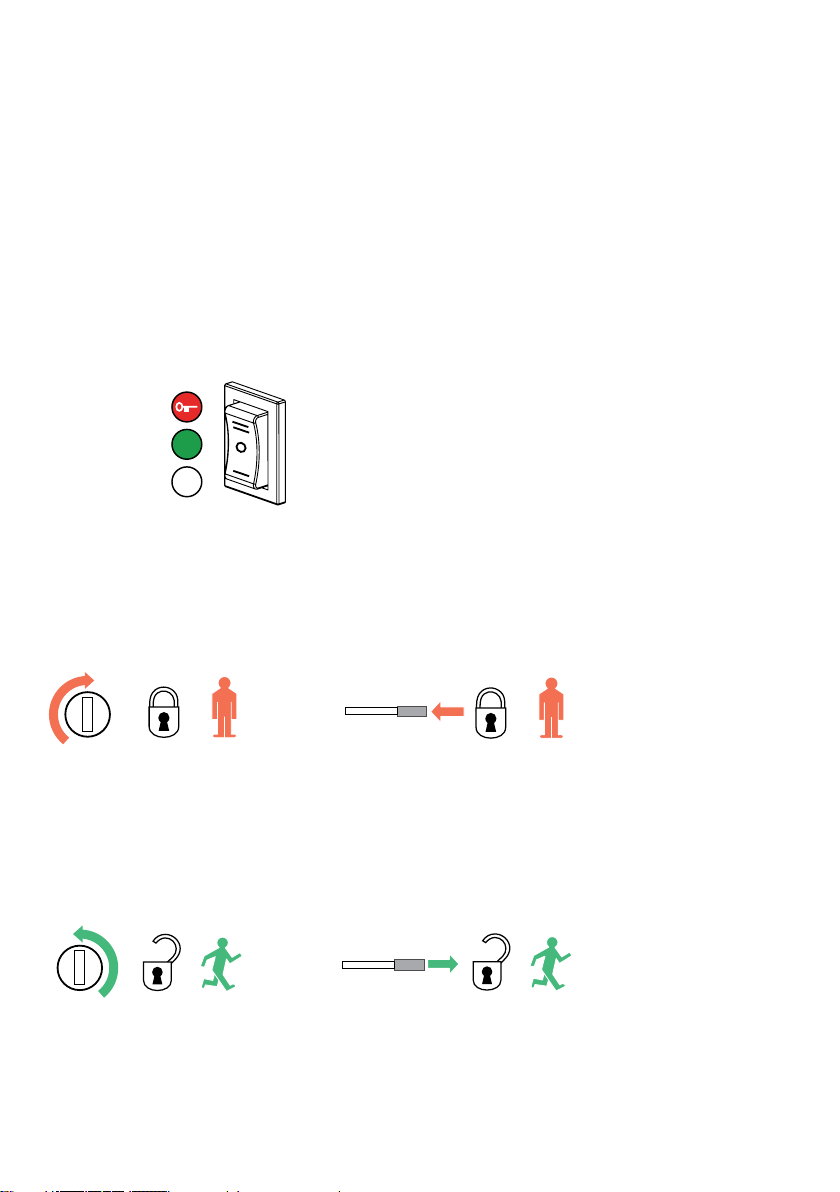
4.3 Operation with an Operating Mode Switch
Selection of Operating Modes
The operating mode can be set directly.
(Reset the system after disconnecting the power supply for at least 5 seconds.)
T1305_4
OFF
AUTOMATIC 1
OPEN
T1321_8
T1321_9
T1321_10
T1321_11
iMotion 2301, 2302, 2401 iMotion 2202
iMotion 2301, 2302, 2401 iMotion 2202
4.4 Operation on Power Failure
Manual Locking u
• Turnthemanualoperationknobclockwise(iMotion2301,2302,2401)orpressthemanualoperation
lever inwards (iMotion 2202).
• Pushthedoorclosedbyhanduntilthelatchengages.
• Switch theoperating modeswitchto operating mode OFF. If a TORMAX user interface is used,
operating mode OFF is automatically set when power is reconnected as the lock is engaged.
Manual Unlocking u
• Turnthemanualoperationknobanti-clockwise(iMotion2301,2302,2401)orpullthemanualop-
eration lever outwards (iMotion 2202).
• Pushthedooropenbyhand.
• Settheoperatingmodeswitchtotheoperatingmodeyouwantwhenpowerisrestored.

Instructions for Use iMotion 2202 / 2301/ 2302 / 2401 T-1321 e 13
T1305_5
Opening a Door with a Battery Unit uUsing a Key Switch u
• Turnthekeyswitchtothe“on”positionandholdinplaceforatleast3seconds,thenturnthekey
to the original position.
Thebatteryisactivatedusingthe“wakeup”function.
• Turnthekeybrieytothe“on”positiononcemore.If required,theoperatingmodecanbechanged
on the user interface during the wake-up.
Thekeyswitchmustnotremainpermanentlyinthe“on”opposition.
The door is unlocked and opened.
The battery switches off again.
5 Procedure in the Event of a Fault
Faults are evident from abnormal door behaviour and/or as an error message on the user interface.
Errormessagesontheuserinterfacetaketheformof aashing“E”or“H”followedbytwogures.
H=notication>thesystemcancontinuetobeused.
E=fault>thesystemisstationary.
Some faults or notifications can be rectified by restarting the door drive with a software reset and/or
briefly disconnecting the system from the power supply.
Fault Display and Reset Using the TORMAX User Interface
See the table in section 7.1 for an overview of the fault displays.
Browse through the fault display using selector key 1 upwards
(to display several faults).
1. Reset the error message, press selector key 2 (downwards) briefly.
2. Software reset: press the key for 5 seconds.
Reset of the Fault with the Operating Mode Switch
Software reset in the event of a fault: change the operating mode.
Reset of the Fault by Disconnecting the Power Supply
If the system does not have a battery unit, disconnect from the power supply for about 10 seconds.
If this does not reset the fault or if it re-occurs after a short time, you must arrange for the fault to be
rectified by a specialist from your TORMAX dealer. In this case note the fault number and inform the
dealer. See the last page or the service tag on the system for the dealer’s address.
T1305_4

14 Instructions for Use iMotion 2202 / 2301/ 2302 / 2401 T-1321 e
6 Maintenance
The system was tested and approved by an expert before initial commissioning. The manufacturer
recommends that you conclude a service contract in order to maintain the value of your system for as
long as possible as well as to ensure the system operates reliably and safely for a long time.
Only genuine TORMAX spare part should be used. The manufacturer accepts no liability if you fail
to observe this requirement. Original spare parts and original accessories guarantee the safety of
use in accordance with norm EN 16005.
The following maintenance work must be carried out:
6.1 Cleaning
Warning
Closing doors can crush – danger!
Trapped limbs can lead to serious injury.
• ThesystemmustonlybecleanedinoperatingmodeOFF,OPENorManualOperation.
• Cleancasingparts,theuserinterfaceanddoorleaveswithadampclothanda
commercial cleaner.
6.2 Functional Checks
The operator must check the function and safety devices of the automatic sliding door at least
every 3 months. This will ensure that faults or hazardous changes in the system are detected at an
earlystage.Seesection7.2“Check-listforFunctionalChecks”foritemstobechecked.
You should arrange for any defects detected during the routine checks to be rectified immediately by a
TORMAX dealer (see the last page of this Manual for the address).
Warning
Potential switching malfunction in the automatic sliding door.
Potential hazards – injury caused by impact or crushing.
6.3 Maintenance and Testing
Maintenance and testing should only be carried out by a trained specialist following the manufacturer’s
instructions.
Maintenance Interval
The maintenance interval depends on the frequency of use but the system must be maintained at
least once per year.
Scope of the Maintenance Work
The content of the maintenance work is specified by the manufacturer in an inspection list.
System Test Book
The test findings are recorded after the test in the system test book. The operator must keep it in a safe
place.

Instructions for Use iMotion 2202 / 2301/ 2302 / 2401 T-1321 e 15
7 Appendix
7.1 Fault Table
System Behaviour No. Cause Remedy/ Rectification
The door stops when
opening.
H91 Electronic obstacle recognition on
opening by a person, wind pressure,
ventilation or dirt in the floor guide.
Remove the obstruction. Clean the
floor guide in operating mode P.
Door reverses when
closing.
H92 Electronic obstacle recognition on
closing by a person, wind pressure,
ventilation or dirt in the floor guide.
Remove the obstruction. Clean the
floor guide in operating mode P.
The door stops repeat-
edly when opening.
H93 Electronic obstacle recognition on
opening in the same position by
stationary obstacle.
Remove the obstruction. Clean the
floor guide in operating mode P.
The door stops repeat-
edly when closing.
H94 Electronic obstacle recognition on
closing in the same position by sta-
tionary obstacle.
Remove the obstruction. Clean the
floor guide in operating mode P.
Search run notified. H61
H62
Search run of the door after a reset
or after power recovery.
Allow the search run to travel its full
course.
Door operates at a re-
duced speed.
H71 Battery operation Wait for power recovery
Switch on mains supply.
Door remains closed. – Operating mode such as OFF, EXIT
or P.
E.g. select operating mode
AUTOMATIC 1.
Door remains open. – Operating mode such as OPEN or P. E.g. select operating mode
AUTOMATIC 1.
The door does not lock
in OFF.
E11 Lock is jammed or defective. Push the door leaves for a few sec-
onds against the closed position in
operating mode OFF when the door
is closed. Have the system repaired
by experts.
The door does not open
after changing from
OFF to AUTOMATIC.
The lock makes switch-
ing noises from time to
time.
E11 Lock is jammed or defective. Push the door leaves for a few sec-
onds against the closed position in
operating mode AUTOMATIC 1.
Have the system repaired by ex-
perts.
The door does not open
in OFF when the key
switch is used. The lock
makes switching noises.
E11 Lock is jammed or defective.. Switch on with the key switch and
then push the door leaves briefly
against the closed position.
Have the system repaired by ex-
perts.
Dependent on configura-
tion.
E2
...
Error in bus system Have the system repaired by ex-
perts.
The door closes slowly. E30
E34
The safety facility in the closing direc-
tion is permanently active (>1 min-
ute) or defective.
Remove objects from within the
range of the sensor(s). Otherwise
have the system repaired by an
expert.
Door remains closed. E31
E37
The safety facility in the opening di-
rection is permanently active (>1
minute) or defective.
Remove objects from within the
range of the sensor(s). Otherwise
have the system repaired by an
expert.

16 Instructions for Use iMotion 2202 / 2301/ 2302 / 2401 T-1321 e
System Behaviour No. Cause Remedy/ Rectification
The door opens slowly. E32
E38
The safety facility in the opening di-
rection is permanently active (>1
minute) or defective.
Remove objects from within the
range of the sensor(s). Otherwise
have the system repaired by an
expert.
The door remains
open.
E33
E39
The safety facility in the closing direc-
tion is permanently active (>1 min-
ute) or defective.
Remove objects from within the
range of the sensor(s). Otherwise
have the system repaired by an
expert.
The door remains open. E41
E42
E43
Activator inside is active > 1 min.
Activator outside is active > 1 min.
Key switch is active > 1 min.
Get sensor adjusted by a profes-
sional.
Reset the key switch.
Door remains open. E46 Emergency opening monitoring > 10
mins. active
Have the system repaired by ex-
perts.
The door stands still. E51 Encoder defective. Have the system repaired by ex-
perts.
The door stands still. E53
E54
E55
E56
Anomaly in the travel distance.
Solid obstruction in the movement
area.
Remove firm obstacle in the trav-
elling range of the door.
Perform a software-reset.
Have the system repaired by ex-
perts.
The door stands still. E61
E62
E63
Power supply is overloaded or volt-
age too low.
Get the power supply and connec-
tions checked by a professional.
The door stands still. E64
E65
Drive/control system is overheated. Wait for the automatic reset after
the door/control system has
cooled.
Protect from direct sunlight.
The door stands still. E66 Motor control defective. Have the system repaired by ex-
perts.
Normal operation E67 Drive heavily loaded. Wait for the automatic reset
Otherwise have the system re-
paired by an expert.
Door remains open or
normal operation.
E72 Battery charge < 15 % Wait until battery is sufficiently
charged
Door remains open or
normal operation.
E73 Battery unit defective Have the system repaired by ex-
perts.
The door stands still. E8.. Control system shut down for
safety reasons.
Perform a software-reset.
Have the system repaired by ex-
perts.
The door collides with
people.
–Safety device or setting inadequate. Shut down the system.
(see section 2.6).
Instructions for Use iMotion 2202 / 2301/ 2302 / 2401 T-1321 e 17
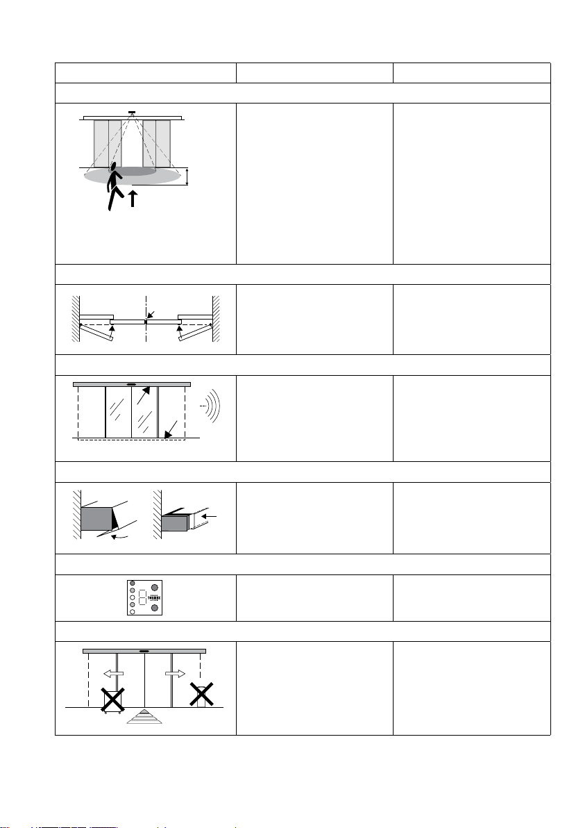
7.2 Check-list for Functional Checks
Item To Be Checked Procedure Result
Sensors
T1321_18
min. 1 m
• Walkthroughthedoordirect-
ly from the front and from dif-
ferent directions at normal
speed, starting both from the
inside and outside
The door opens at the right time
and with sufficient speed so that
passage through the door Is not
hindered.
• Walkthroughthedoordirect-
ly from the front and from dif-
ferent directions at a slow
speed like an infirm person,
starting both from the inside
and outside.
The door opens and remains
open until you are completely
through the door.
Moving Leaves, Side Parts, Fixed Leaves
• Checktheglassdoorllings,
door edges and rubber pro-
files for damage.
The door fillings have no sharp
edges and splintered glass.
The side parts and the door
seals are in place and undam-
aged.
Guide System and Door Guides
T1321_2
• Checkthenoisesmade
while the door moves.
No unusual and noticeable
movement noises can be heard
in the drive, guide system or
floor guides.
Cladding
iMotion 2301 / 2302 / 2401 iMotion 2202
• Checkwhetherthecladding
is correctly slotted into place
and secured.
The cladding is firmly slotted
into place.
Operating Controls
3
• Checkthefunctionand
marking of operating con-
trols.
The operating controls are func-
tioning correctly; the markings
are visible and legible.
System Vicinity
T1321_12
• Checkaccesstothedoor
and the movement area of
the door leaves.
Access to the door is free from
objects and items likely to cause
the user to trip. There are no
objects such as shelves, plant
containers and umbrella stands
within a radius of 50 cm of the
movement area.
18 Instructions for Use iMotion 2202 / 2301/ 2302 / 2401 T-1321 e
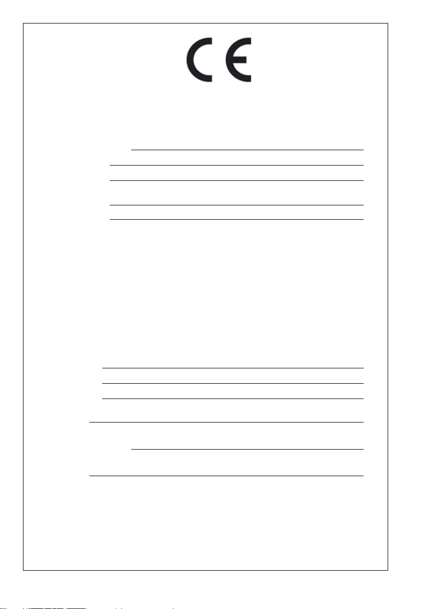
T-1063 e Declaration of Conformity
EG Declaration of Conformity
The manufacturer declares
Manufacturer’s address:
that the product (machine)
Type designation:
Serial number:
is in conformity with the guideline EG-RL 2006/42/EG
is in conformity with regulations of the guidelines:
- 2006/95/EG (low tension)
- 2004/108/EG (electro-magnetic-compatibility)
and the following harmonised standards have been adhered to:
- EN 16005
Base document: Declaration of incorporation by TORMAX | Landert Motoren AG
Person responsible for documents
Name/address:
Place, date:
Signatory
(CE authorized person):
Signature:

This manual suits for next models
6
Table of contents
Other Tormax Door Opening System manuals


Popular Door Opening System manuals by other brands


Dormakaba
Dormakaba TS 97 FL XEA Mounting instructions

D+H
D+H VRS 10 Original instructions

GEZE
GEZE TSA 160 NT Installation and service instructions

LCN
LCN 4020 Series installation instructions

FlexiForce
FlexiForce ISC-NL Installation & maintenance

Assa Abloy
Assa Abloy Norton 5500 Series installation instructions

Horton
Horton C2150 Setup instructions

Roto
Roto E-Tec DoorDrive Installation, maintenance and operation instructions

LCN
LCN 4412 HSA Installation instructions and operators manual

Dorex
Dorex 1900 Series installation instructions

raumplus
raumplus 800 AIR-B Series Assembly & installation

Dormakaba
Dormakaba ED50 installation instructions