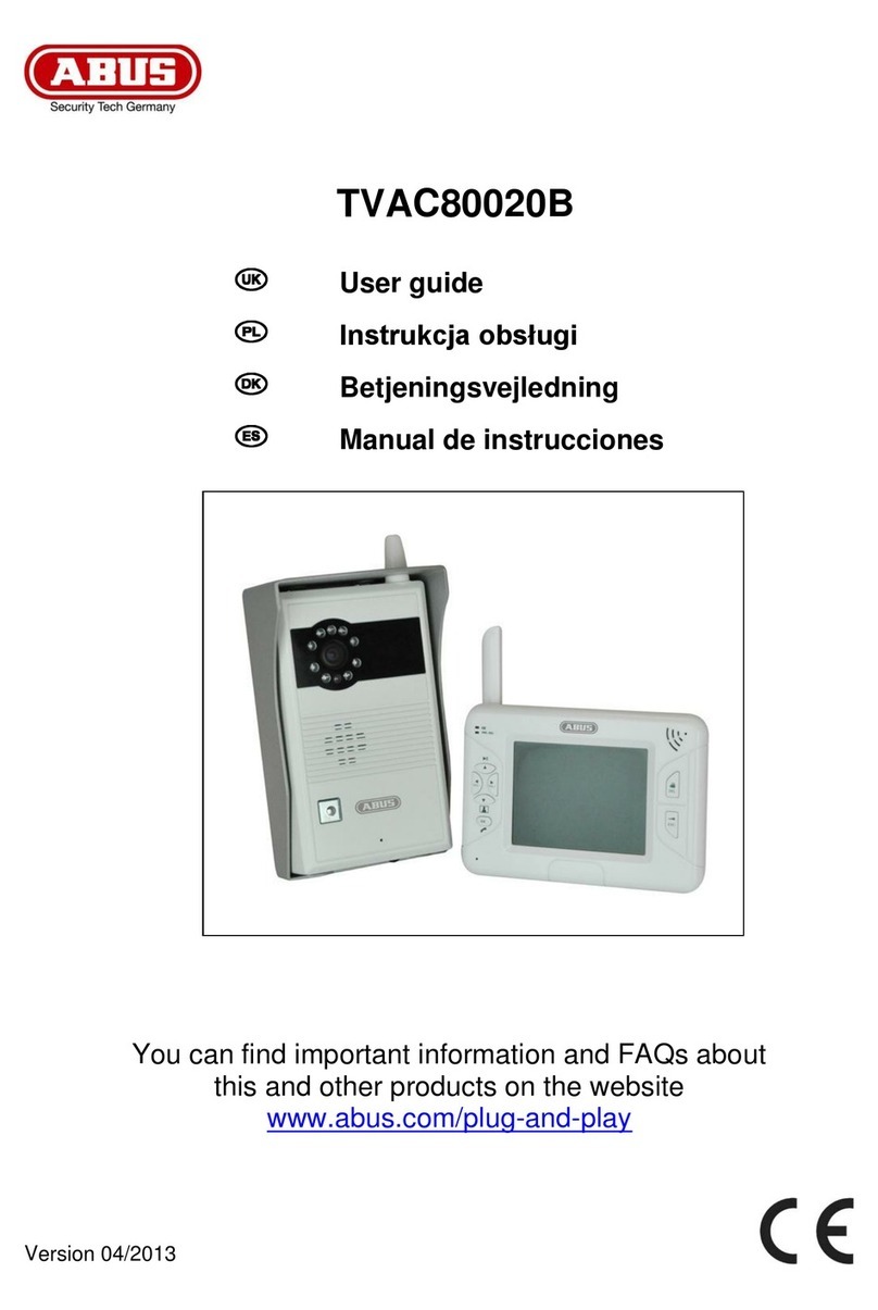
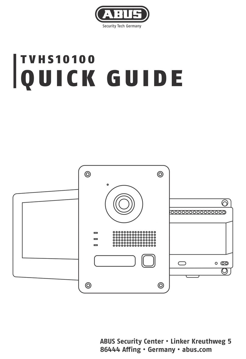
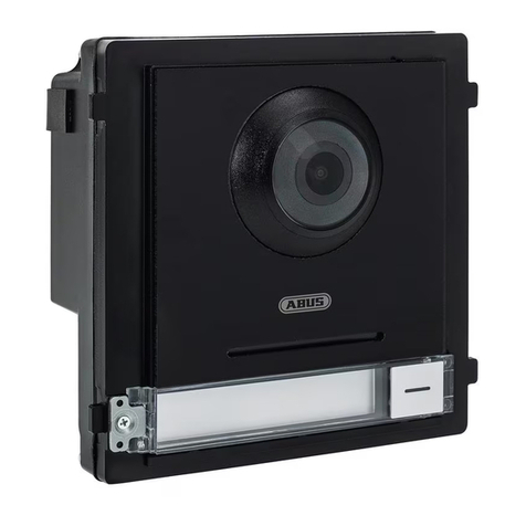
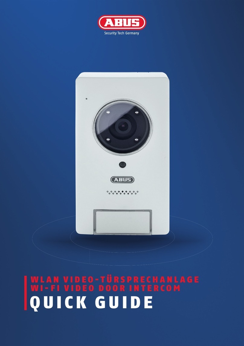
Abus TVHS10100 User manual

ABUS Security Center • Linker Kreuthweg 5
86444 Aing • Germany • abus.com
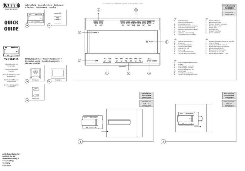
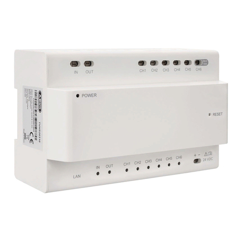
TVHS10100
QUICK GUIDE

1. Betriebs-LED
2. Info-LED
3. Alarm-LED
4. Anruf annehmen / ablehnen
5. Türöner
6. Live-Ansicht
7. Nicht verwendet
8. LCD-Bildschirm
9. Mikrofon
10. 2-Draht Verbindung
11. Nicht verwendet
12. Anschluss für Servicezwecke
13. microSD-Karten Slot (max. 32 GB)
14. Lautsprecher
1. Power LED
2. Info LED
3. Alarm LED
4. Accept/reject call
5. Door opener
6. Live view
7. Not used
8. LCD screen
9. Microphone
10. 2-wire connection
11. Not used
12. Connection for service purposes
13. microSD card slot (max. 32 GB)
14. Loudspeaker
1. LED de fonctionnement
2. LED d‘info
3. LED d’alarme
4. Accepter/refuser un appel
5. Ouvre-porte
6. Achageentempsréel
7. Nonutilisé
8. Ecran LCD
9. Microphone
10. Connexion2ls
11. Nonutilisé
12. Portréservéauservice
13. Logement de carte microSD (max. 32 Go)
14. Haut-parleur
1. Bedrijfs-LED
2. Info-LED
3. Alarmled
4. Oproep aannemen/weigeren
5. Deuropener
6. Live-weergave
7. Niet gebruikt
8. LED-beeldscherm
9. Microfoon
10. 2-draads verbinding
11. Niet gebruikt
12. Aansluiting voor servicedoeleinden
13. microSD-kaartslot (max. 32GB)
14. Luidspreker
1. Dris-LED
2. Info-LED
3. Alarm-LED
4. Besvar / afvis opkald
5. Døråbner
6. Livevisning
7. Ikke anvendt
8. LCD-skærm
9. Mikrofon
10. 2-trådet forbindelse
11. Ikke anvendt
12. Tilslutning til serviceformål
13. microSD-kort-slot (maks. 32 GB)
14. Højtaler
1. LED di funzionamento
2. LED di avviso
3. LED di allarme
4. Accettazione/riutochiamata
5. Apriporta
6. Visualizzazione live
7. Non utilizzata
8. Schermo LCD
9. Microfono
10. Collegamentoa2li
11. Non utilizzata
12. Collegamento per l‘assistenza
13. Slot per schede micro SD (max. 32 GB)
14. Altoparlante
Übersicht
Overview • Vue d‘ensemble • Overzicht • Oversigt • Panoramica
1
1. Mikrofon
2. „Anruf“ Anzeige
3. „Sprechen“ aktiv
4. „Türöner“aktiv
5. Kameramodul
6. IR LED`s für Nachtsicht
7. Lautsprecher
8. Klingeltaste
9. Sabotagekontakt
10. Montagerahmen
1. Microphone
2. “Call” display
3. “Speak” active
4. “Door opener” active
5. Camera module
6. IR LEDs for night vision
7. Loudspeaker
8. Call button
9. Tamper contact
10. Installation frame
1. Microphone
2. Achage„Appel“
3. „Parler“ actif
4. „Ouvre-porte“ actif
5. Moduledecaméra
6. LED IR pour vision nocturne
7. Haut-parleur
8. Bouton de sonnette
9. Contact antisabotage
10. Cadre de montage
1. Microfoon
2. Indicatie „Oproep“
3. „Spreken“ actief
4. „Deuropener“ actief
5. Cameramodule
6. IR-LEDs voor nachtzicht
7. Luidspreker
8. Beltoets
9. Sabotagecontact
10. Montageraam
1. Mikrofon
2. Visning af „opkald“
3. „Tale“ aktiv
4. „Døråbner“ aktiv
5. Kameramodul
6. IR-LED‘er til natsigt
7. Højtaler
8. Ringeklokke
9. Sabotagekontakt
10. Montageramme
1. Microfono
2. Avviso di chiamata
3. Voce attiva
4. Apriporta attivo
5. Modulo telecamera
6. LED IR per visione notturna
7. Altoparlante
8. Tasto del campanello
9. Contatto antimanomissione
10. Quadro di installazione
6
2
1
4
3 7
5
81
8
2
3
4 5 6 7 9
14
11
13
10
12
10

1. Reset Taste
2. Power-LED
3. 2-Draht Verbindung
4. RJ-45 Anschluss
5. Spannungsversorgung 24 V DC
1. Reset button
2. Power LED
3. 2-wire connection
4. RJ-45 connection
5. Power supply, 24 V DC
1. Touche Reset
2. LED d’alimentation
3. Connexion2ls
4. Raccord RJ-45
5. Tension d‘alimentation 24 V CC
1. Resettoets
2. Power-LED
3. 2-draads verbinding
4. RJ-45-aansluiting
5. Voedingsspanning 24 V DC
1. Reset-tast
2. Power-LED
3. 2-trådet forbindelse
4. RJ-45-tilslutning
5. Spændingsforsyning 24 V DC
1. Tasto reset
2. LED di alimentazione
3. Collegamentoa2li
4. Collegamento RJ-45
5. Alimentazione di tensione 24 V CC
Installation
Installation • Installation • Installatie • Installation • Installazione
i
System
structure
System Auau
Türstation
Door Station
24V DC
Anschluss
24V DC
input
2-Draht
Leitung
2-wire
cable
Verteiler
Distributor
Monitor
Indoor Station
Netzwerk
Network
1
3
2
5
4
2-Draht
Leitung
2-wire
cable
iDVR Plus
(iOS / Android)
i
Stellen Sie sicher, dass alle zugehörigen Geräte während der Installation ausgeschaltet sind.
Wählen Sie den Kabeltyp entsprechend dem Abstand zwischen der Türstation und dem Video- / Audio-Verteiler.
Makesureallrelateddevicesareturnedoduringinstallation.
Select the cable type according to the distance between the door station and the video / audio distributor.
Cable
overview
Kabelübersicht
Kabeltyp
Cable type
Widerstand
pro 100 m
Resistance per
100 m
Max.
Übertragungs-
distanz
Max. transmission
distance
Max. Entfernung
(Kein Strom für das
elektronische Schloss)
Max. distance
(No power for the
electronic lock)
Max. Entfernung
(Inklusive Strom für das
elektronische Schloss)
Max. distance
(Including power for the
electronic lock)
24AWG 10Ω 50 m 50 m 30 m
20AWG 7Ω 100 m 100 m 80 m
18AWG 4Ω 150 m 150 m 100 m

1.2
1.1
160-165cm
1.41.3
Surface
mounting
Aufputz-
montage
Surface
mounting
Aufputz-
montage
Surface
mounting
Aufputz-
montage
Surface
mounting
Aufputz-
montage
Hardwareinstallation
Hardware installation • Installation matérielle • Installatie hardware •
Hardwareinstallation • Installazione dell’hardware
1.5
Surface
mounting
Aufputz-
montage
Schrauben vorsichtig anziehen
Carefully tighten the screws

2.22.1
2.42.3
In-wall
mounting
Unterputz-
montage
In-wall
mounting
Unterputz-
montage
In-wall
mounting
Unterputz-
montage
In-wall
mounting
Unterputz-
montage
Meißeln Sie ein
Loch in die Wand.
Die Größe des Lochs
sollte 104 mm (Breite)
× 163 mm (Höhe)
× 39 mm (Tiefe)
betragen.
Chisel a hole in the
wall. The size of the
hole should be
104 mm (width)
× 163 mm (height)
× 39 mm (depth).
160-165cm
2.6
2.5
In-wall
mounting
Unterputz-
montage
In-wall
mounting
Unterputz-
montage
Schrauben vorsichtig anziehen
Carefully tighten the screws

3.23.1
3.43.3
Installation
with housing
Montage mit
Schutzgehäuse
Installation
with housing
Montage mit
Schutzgehäuse
Installation
with housing
Montage mit
Schutzgehäuse
Installation
with housing
Montage mit
Schutzgehäuse
160-165cm
3.5
Installation
with housing
Montage mit
Schutzgehäuse
Schrauben vorsichtig anziehen
Carefully tighten the screws

4.24.1
4.44.3
Monitor
Installation
Innen-Station
Installation
Monitor
Installation
Innen-Station
Installation
Monitor
Installation
Innen-Station
Installation
Monitor
Installation
Innen-Station
Installation
160-165cm
4.5
Monitor
Installation
Innen-Station
Installation

5.1 5.2
Installation
with screws
Installation
mit Schrauben
Installation
with screws
Installation
mit Schrauben
6.2
6.1
Installatin
with DIN rail
Installation mit
DIN-Hutschiene
Installatin
with DIN rail
Installation mit
DIN-Hutschiene
i
Wiring
Verdrahtung
CH1*
CH1*
CH2 – CH7*
CH2 – CH7*
+ (red)(black)-
Verdrahtung
Wiring • Le câblage • Bedrading • Ledninger • Cablaggio
i
Wiring
Verdrahtung
CH1
CH1
CH2 – CH7
CH2 – CH7
+ (red)(black)-
Türöner
Door opener
SpannungsversorgungTüröner
Power supply door opener
Optional
TVHS10040
* Polarität muss nicht beachtet werden
*No need to respect the polarity

1x 1x1x
i i
Die Installations-/Bedienungsanleitung können Sie unter folgendem Link downloaden: abus.com/ger/products/TVHS10100 | You can download the user guide/
installationinstructionsviathelinkbelow:abus.com/eng/products/TVHS10100|Lesinstructiondeservice/instructionsd‘installationpeuventetretéléchargées
sous le lien suivant : abus.com/fr/products/TVHS10100 | De installatie-/gebruikershandleiding kunt u via de volgende link downloaden: abus.com/nl/products/
TVHS10100 | Du kan downloade installations-/betjeningsvejledningen pa folgende link: abus.com/eng/products/TVHS10100| Du kan ladda ner installations-/
bruksanvisningenfranföljandelänk:abus.com/eng/products/TVHS10100|Instrukcjaobsługi/instalacjijestdostępnadopobraniapodnastępującymadresem:
abus.com/pl/products/TVHS10100 | Le istruzioni per l‘installazione e per l‘uso possono essere scaricate dal seguente link: abus.com/it/products/TVHS10100 |
Las instrucciones de uso/instalación pueden descargarse en el siguiente enlace: abus.com/es/products/TVHS10100
Lieferumfang
Scope of delivery • Contenu de la livraison • Leveromvang •
Indhold i kassen • Fornitura
Empfohlenes Zubehör
Recommended accessories • Accessoires recommandés • Aanbevolen
accessoires • Anbefalet tilbehør • Accesorios recomendados
1x 1x
IPCB44510A IPCB64510A
2x
1x
Other manuals for TVHS10100
2
Table of contents
Other Abus Intercom System manuals

Abus
Abus MODUVIS TVHS20 Series User manual

Abus
Abus Eycasa CASA30100 User manual

Abus
Abus TVHS10100 User manual

Abus
Abus TVHS20310 User manual

Abus
Abus TVHS20310 User manual

Abus
Abus MODUVIS TVHS20 Series User manual

Abus
Abus TVAC80000A User manual

Abus
Abus TVAC80020B User manual

Abus
Abus Eycasa CASA30100 User manual

Abus
Abus TVAC80020B User manual