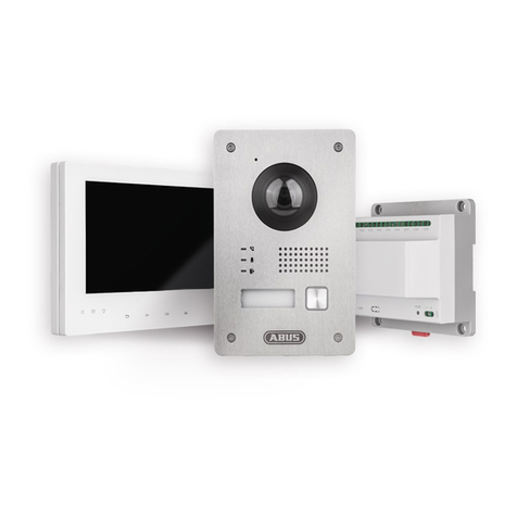
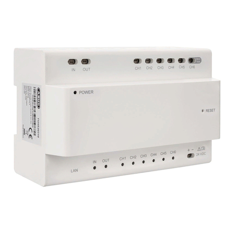
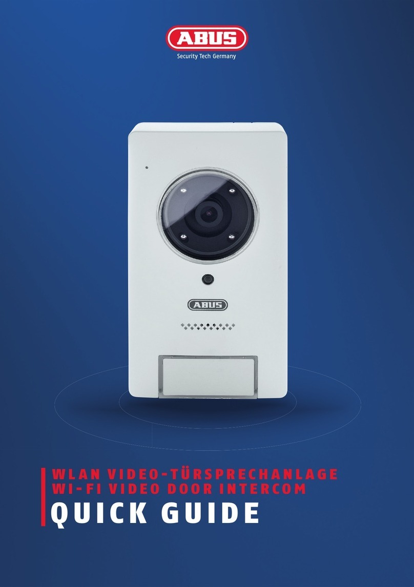
Abus TVHS10100 User manual

TVHS10100
User manual
Original user manual in German. Keep for future use.
This user manual contains important information for installation and operation.
This should be also noted when this product is passed on to a third party.
Therefore look after these operating instructions for future reference!
Version 06/2019

2
CONTENT
Declaration of conformity............................................................................................ 3
Features ..................................................................................................................... 4
Scope of delivery........................................................................................................ 4
Installation (System overview).................................................................................... 5
Door station............................................................................................................. 5
Monitor.................................................................................................................... 6
Secure-Module TVHS10040................................................................................... 6
System structure with security module.................................................................... 7
Attention.................................................................................................................. 7
Cable type............................................................................................................... 7
System Configuration ................................................................................................. 8
Menu description........................................................................................................ 9
Main menu.............................................................................................................. 9
Settings..................................................................................................................... 11
ABUS IP Installer and integration of door station-camera into ABUS NVR............... 14
Integration of door station into ABUS NVR and ABUS iDVR Plus App..................... 14

3
Declaration of conformity
ABUS Security Center hereby declares that the enclosed product complies with the
requirements of the following directives concerning the product:
EMC Directive (2014/30/EU)
Low Voltage Directive (2014/35/EU)
RoHS Directive (2011/65/EU)
The full EU declaration of conformity can be obtained from the following address:
ABUS Security Center GmbH & Co. KG
Linker Kreuthweg 5
86444 Affing
GERMANY
www.abus.com/product/Itemnumber
(‘Item number’ in the link to be replaced with
the article number of the enclosed product)

4
Features
•2-wire ABUS video door intercom
•Complete package with door station, 7” touchscreen monitor, and
distributor
•Reliable and fail-safe monitoring of the entrance area
•Integrated 2 MPx wide-angle camera with IR-LEDs (day-night function)
•Robust stainless steel case with illuminated name plate and call button
•Live view of compatible ABUS IP cameras
•Use up to 6 interior monitors per door station
•Other features such as message recording, automatic response, etc.
•Optional security module for additional manipulation protection
Scope of delivery
2-wire monitor for door station
•2-wire monitor for door station
•Mounting material
•Mounting plate
•2 x Connection cable
•Clamp
•Safety information
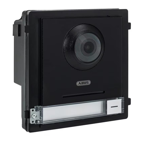
2-wire door station
•2-wire door station
•Flush installation box for door station
•Installation Tool
•Mounting material
•Power supply
•Safety information
2-wire video/audio distributor
•2-wire video/audio distributor
•Mounting material
•Adapter cable

5
Installation (System overview)
Wire the main monitor to channel 1 (CH1) on the Video / Audio Distributor. You can
connect up to 5 more monitors to the Video / Audio Distributor. Wire each monitor to
channels 2 to 6 (CH2 - CH6). The Video / Audio Distributor TVHS10010 can be
supplied with power with the attached power supply (24V DC).
Door station
Connect the 2-wire cable at the door station to the contacts "PLC". The system can
only contain one door station.
Note: The polarity at the different channels CH1-CH9 does not have to be
considered. Door station and monitors have no polarity marking. No special
sequence must be observed on the channels, each channel can operate any type of
device (door station, main and additional monitor).
An electric door opener is connected to the door station at "Door". In the door station
there is a potential-free relay. This has the contacts "NC" (Normally closed, =>
Normally closed contact) and "NO" (Normally open => Normally open contact)
The connections "IO1" and "IO2" are not needed.
2-wire cable
2-wire cable
Monitor
Door station
Video / Audi Distributor
Network cable
IP Camera

6
Monitor
Connect the 2-wire cable to the monitor as shown in the following sketch. There is no
polarity to be considered.
Only the 2 upper contacts of the green terminal block (6-PIN) are used on the
monitor. The other contacts and connections are currently not used.
Secure-Module TVHS10040
This safety module is connected via RS-485 to the door station on the contacts "RS-
485". The safety module must be installed in a safe, non-accessible location. Only
then it is ensured that unauthorized persons cannot gain access to the door contact
cables. The safety module prevents the door contact cabling from being directly
accessible from outside in the case of sabotage.
The safety module requires a separate power supply of 12V DC.
The door contact relay of the safety module is potential-free and has to be used with
max. 2A 30VDC / 0.5A 125AC switch.

7
System structure with security module
The safety module uses only the connection "Power IN" (12VDC) / "RS485"
(connection to door station "RS485" and "lock out"), the other connections are
currently not used.
Attention
Make sure all related devices are turned off during installation.
Cable type
Select the cable type according to the distance between the door station and the
video / audio distributor.
Cable
typ
Resistance
per 100 m
Max.
Transmission
distance
Max. Distance
(Door station does
not supply power
for the electric
door opener)
Max. Distance
(The door station
supplies power for the
electric door opener)
24AWG
10 Ω
50 m
50 m
30 m
20AWG
7 Ω
100 m
100 m
80 m
18AWG
4 Ω
150 m
150 m
100 m
Door
station
Monitor
Main
distributor
TVHS10040
RS-485
12V DC
Door opener with its
own power supply

8
System Configuration
Before you start:
•Make sure that the video / audio distributor is connected to a router via a
network cable (the DHCP feature is enabled by default).
•Make sure the monitor and the door station are connected to the video /
audio distributor via 2-wire cable.
•Make sure all devices are turned on during activation.
Note:
The video / audio distributor TVHS10100 does not necessarily has to be
connected to the LAN. Without the Internet, the time must be set manually
because no connection to the NTP server can be established. If no external
cameras are integrated or accessed via app, you can omit the connection to the
home network.
1) Activate device
You must first enable the device by setting a strong password before you can use
the device.
2) Select language
Select one of the available languages from the drop-down list.
3) Select device mode
You must define a monitor as the main monitor (in a multi-monitor installation,
only one monitor can be defined as the main monitor).
4) Select door station (only with main monitor)
Here you select the door station from the drop-down list
(the search may take a few seconds).
5) Select main monitor (only with additional monitors)
Here you select the main monitor from the drop-down list. All additional monitors
are connected to the main monitor.
6) Finished

9
Menu description
Main menu
The main menu shows the current time and date, as well as the connection status of
the door station (top right in the screen).
Touch the time or date for 2 seconds to adjust it.
Furthermore, the following functions are available:
Note: Some configuration options are only available on the main monitor.
Dial
Call
Here you can call another monitor (assuming there is more than 1 monitor
installed in the system).
Select the internal number (1 to 5) of the additional monitor and press the call
key. The main monitor always has the phone number "0".
Log
Calls from the door station or from other monitors are listed here.
Contacts
This feature is currently not available.
Information
Message
Here you can see an overview of all messages left by a caller and can play
them (requires an inserted and configured microSD card - max 32 GB).
Picture
Pressing the bell button automatically saves an image
(requires an inserted and configured microSD card - max 32 GB).
Here you can see an overview of all pictures and have a look at them. If you
touch a picture for more than 2 seconds, a menu appears to delete this picture
or to clear the entire list.
If multiple monitors are used, a microSD card can be inserted into each device
as needed. The images are then available on every monitor.
Attention: The recorded audio file of the answering machine can only be
monitored on the main monitor.
Alarm log
Here you can see if the sabotage alarm of the door station (located on the rear
side) has been triggered.
10
Live view
Switches to the live view of the door station. From here you can also open the live
view of installed network cameras.
Draw area
Here you can define an area to be digitally zoomed.
Note: The system must be restarted to successfully apply the zoom setting.
Clear area
Here you can delete the previously defined area again.
Set area
Here you confirm the previously defined area. After that, you must disconnect
the system from the power and restart it to apply the changes.
Reset
Here you can reset the settings of the digital zoom.
Enable
Here you can start the speech communication via the door station.
Door opener (lock icon)
Here you can activate the door opener (if connected).
Hibernate
Puts the monitor into standby mode.
Settings
Switches to the Settings menu.

11
Settings
The Settings menu allows you to make all the essential settings for the monitor or
your system.
Password
Here you can change the password assigned during the initial setup.
This password is needed when accessing the system via network.
Sound
Ringtone
Here you can choose between three different ringtones.
Ringtone duration
Here you can define the ringing time (30 to 60 seconds).
Microphone volume
Here you can define the microphone volume from the monitor -
"0" very quiet to "10" very loud.
Speaker volume
Here you can define the speaker volume from the monitor -
"0" very quiet to "10" very loud.
Touch sound
Here you can switch the key tone on or off when using the monitor.
Enable auto answer
If this function is activated, the absence message at the door station will be
played immediately when the bell button is pressed (the message itself cannot
be changed).
DND (Do not disturb) settings
If this function is activated, the call from the door station or another monitor will not be
forwarded to any monitor.
All day
Function is activated permanently.
Schedule
Function is activated within the time defined below.
Maintenance
microSD Card
Here you can format a microSD card inserted in the monitor (up to 32 GB).

12
Clean screen
Here you can lock the screen so that no function is accidentally triggered when
the screen is cleaned.
General information
Modell: Displays the item number of the monitor
Version: Displays the installed firmware version
SN: Displays the serial number of the monitor
Code: This function is currently not used
System language
Here you can choose the display language - German, English, French, Italian,
Danish, Dutch.
Config
Here you can open the advanced settings.
The password for this is: "888999" (the password cannot be changed).
Local info
Monitor type
Here you can define whether the monitor is the main monitor or an additional
monitor (only one main monitor can be defined per system).
Monitor nr.
This feature is currently not available.
Live view duration
Here you can set the display duration of the live image view -
10 to 60 seconds.
Network
Here you can activate the automatic assignment of network parameters via DHCP or
manually enter the network parameters.
Camera
You can add network cameras* that are within the network. These can then be
selected in live view. Click "+" to add a camera, entering the IP address, the RTSP
port (usually 554) and the admin username and password.
* Network cameras must be compatible
NTP
Here you can set an NTP server. The NTP server then automatically synchronizes
the time and date with the system.

13
Search
Here, devices added to the respective monitor are displayed.
Click on "..." for further settings.
Example: For the main monitor, the door station is displayed; for the additional
monitor, the main monitor is displayed.
Reset Restore
Resets all settings except password and network settings.
Default
Resets all settings, including password and network settings.
* Compatible ABUS IP cameras
IPCA33500, IPCA53000, IPCA62520, IPCA63500, IPCA66500, IPCA72520,
IPCA73500, IPCA76500, IPCB42500, IPCB42501, IPCB42510A, IPCB42510B,
IPCB42510C, IPCB42515A, IPCB42550, IPCB42551, IPCB44510A, IPCB44510B,
IPCB44510C, IPCB62500, IPCB62510A, IPCB62510B, IPCB62510C, IPCB62515A,
IPCB62520, IPCB64510A, IPCB64510B, IPCB64510C, IPCB64515B, IPCB64520,
IPCB64620, IPCB68510A, IPCB68510B, IPCB68510C, IPCB68515A, IPCB68520,
IPCB68620, IPCB72501, IPCB72515A, IPCB72520, IPCB74515B, IPCB74615B,
IPCB74520, IPCB78515A, IPCB78615A, IPCB78520

14
ABUS IP Installer and integration of door station-camera
into ABUS NVR
With the ABUS IP Installer you can set the network settings of the door station and
monitors via network. Please enter the user name (admin) and your password for the
advanced functions of the IP installer.
Note: Normally, access to the door station and associated components via the IP
installer is not necessary. The complete installation takes place on the local monitor
of the door station.
The devices do not have a standalone web interface.
Integration of door station into ABUS NVR and ABUS iDVR
Plus App
You can integrate the camera of the door station in your existing ABUS NVR for
recording. The live image of the door station can also be viewed in the ABUS iDVR
Plus app.
The following parameters are required for integration:
- IP address of the door station TVHS10000A
- User name of the door station (admin)
- Password (this was defined when setting up the main monitor)
- Port 8000

15
Imprint
These operating instructions are published by ABUS Security Center GmbH & Co.KG, Linker
Kreuthweg 5, 86444 Affing, Germany. No reproduction (including translation) is permitted in whole or
part e.g. photocopy, microfilming or storage in electronic data processing equipment, without the
express written consent of the publisher.
The operating instructions reflect the current technical specifications at the time of print.
We reserve the right to change the technical or physical specifications.
© Copyright 06/2019 by ABUS Security Center
Other manuals for TVHS10100
2
Table of contents
Other Abus Intercom System manuals

Abus
Abus TVHS20310 User manual

Abus
Abus MODUVIS TVHS20 Series User manual

Abus
Abus Eycasa CASA30100 User manual

Abus
Abus TVHS10100 User manual

Abus
Abus TVHS30000 User manual

Abus
Abus ModuVis Set M User manual

Abus
Abus TVHS30000 User manual

Abus
Abus PPIC35520 User manual

Abus
Abus TVAC80020B User manual

Abus
Abus Eycasa CASA30100 User manual